Table of Contents
Advertisement
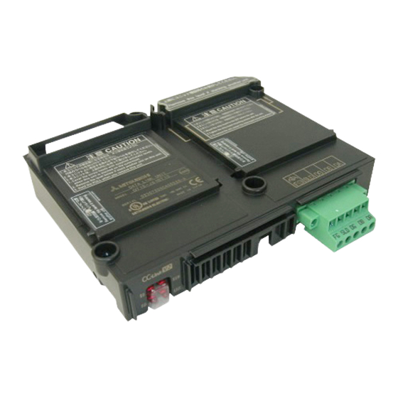
GOT2000/GOT1000 Series
CC-Link Communication
GT15-J61BT13
Thank you for choosing Mitsubishi Electric Graphic Operation Termi-
nal (GOT).
Prior to use, please read both this manual and detailed manual
thoroughly to fully understand the product.
User's Manual
MODEL
GT15-J61BT13-U
MODEL
CODE
IB(NA)-0800351-J(1704)MEE
Unit
1D7M57
Advertisement
Table of Contents

Related Manuals for Mitsubishi Electric GT15-J61BT13


Summary of Contents for Mitsubishi Electric GT15-J61BT13
- Page 1 GOT2000/GOT1000 Series CC-Link Communication Unit User's Manual GT15-J61BT13 Thank you for choosing Mitsubishi Electric Graphic Operation Termi- nal (GOT). Prior to use, please read both this manual and detailed manual thoroughly to fully understand the product. MODEL GT15-J61BT13-U MODEL 1D7M57...
-
Page 2: Safety Precautions
SAFETY PRECAUTIONS (Always read these instructions before using this equipment.) Before using this product, please read this manual and the relevant manuals introduced in this manual carefully and pay full attention to safety to handle the product correctly. The instructions given in this manual are concerned with this product. In this manual, the safety instructions are ranked as "WARNING"... -
Page 3: Installation Precautions
[DESIGN PRECAUTIONS] WARNING Some faults of this unit may keep the outputs on or off. An external monitoring circuit should therefore be provided to check for output signals which may lead to a serious accident. Not doing so can cause an accident due to mis-output or misoperation. ... -
Page 4: Wiring Precautions
[INSTALLATION PRECAUTIONS] CAUTION Use this unit in the environment that satisfies the general specifications described in the User's Manual for the GOT used. Not doing so can cause an electric shock, fire, malfunction or product damage or deterioration. When installing this unit to the GOT, fit it to the connection interface of the GOT and tighten the mounting screws in the specified torque range (0.36 N•m to 0.48 N•m) with a Phillips-head screwdriver No.2. - Page 5 [WIRING PRECAUTIONS] CAUTION Tighten the terminal screws within the specified torque range. Undertightening can cause a short circuit or misoperation. Overtightening can cause a short circuit or misoperation due to damaged screws or unit. Ensure that foreign matters such as chips and wire off-cuts do not enter the unit.
- Page 6 [STARTUP AND MAINTENANCE PRECAUTIONS] WARNING Do not touch the terminals while power is on. Doing so can cause an electric shock or misoperation. Before starting cleaning or terminal screw retightening, always switch power off externally in all phases. Not doing so can cause a unit failure or misoperation.
- Page 7 [TRANSPORTATION PRECAUTIONS] CAUTION Make sure to transport the GOT main unit and/or relevant unit(s) in the manner they will not be exposed to the impact exceeding the impact resistance described in the general specifications of Use this unit in the environment that satisfies the general specifications described in the User's Manual for the GOT used., as they are precision devices.
- Page 8 Cover This manual confers no industrial property rights or any rights of any other kind, nor does it confer any patent licenses. Mitsubishi Electric Corporation cannot be held responsible for any problems involving industrial property rights which may occur as a result of using the contents noted in this manual.
-
Page 9: Table Of Contents
CONTENTS 1. OVERVIEW ....................1 2. SPECIFICATIONS ..................2 2.1 Performance Specifications ..............2 2.2 Specifications of terminal block socket ............ 4 3. I/O SIGNALS AND REMOTE REGISTER ASSIGNMENT ......5 3.1 I/O Signals Transferred to/from the Master Module ........ 5 3.2 Remote Register Assignment .............. - Page 10 Manual The following shows manuals relevant to this product. Detailed Manuals Manual number Manual name (Model code) GOT2000 Series User's Manual (Hardware) SH-081194ENG (Sold separately) (1D7MJ5) GOT2000 Series Connection Manual SH-081197ENG (Mitsubishi Products) For GT Works3 Version1 (1D7MJ8) (Sold separately) GT16 User's Manual (Hardware) SH-080928ENG (Sold separately)
- Page 11 Extension interface relay board Terminating resistor 110 1/2W (brown, brown, brown)* Plate type solderless terminal set Terminating resistor 130 1/2W (brown, orange, GT15-J61BT13 brown)* Plate type solderless terminal set Solderless terrninal (For connecting the braid shield wire, Plate type) Terminal block socket...
-
Page 12: Overview
1. OVERVIEW This user's manual describes the GOT2000/GOT1000 series CC-Link communication unit (hereinafter referred to as the CC-Link communication unit) to be used in the Control & Communication Link (CC-Link) system. For attachable GOTs, refer to the User's Manual for the GOT used. The CC-Link communication unit can be connected to the GOT, which can perform monitoring as an intelligent device station (number of occupied stations selectable from 1 station / 4 stations) in the CC-Link system. -
Page 13: Specifications
2. SPECIFICATIONS 2.1 Performance Specifications The following is the performance specification of CC-Link communication unit. The general specification of the CC-Link communication unit are the same as those of the GOT. For the general specifications of the GOT refer to the User's Manual for the GOT used. - Page 14 *3 The number of link points per station depends on the mode setting of CC-Link as shown below. For CC-Link Ver.2 Number of link points per station Link device Extension cyclic setting Single Double Quadruple Octuple 64 points 128 points Remote I/O(RX, RY) 32 points 32 points...
-
Page 15: Specifications Of Terminal Block Socket
2.2 Specifications of terminal block socket Item Specifications Wiring screw : 0.5 to 0.6 N•m Screw tightening torgue Terminal block fixing screw : 0.7 to 0.8 N•m Flat-blade screwdriver Recommended driver (Blade thickness 0.6mm, Width 3.5mm) -
Page 16: I/O Signals And Remote Register Assignment
3. I/O SIGNALS AND REMOTE REGISTER ASSIGNMENT 3.1 I/O Signals Transferred to/from the Master Module The following table lists the I/O signals assigned to the GOT. The I/O signals differ according to the set number of occupied stations (1 or 4 stations). n in the table indicates the address assigned to the Master module by station number setting. - Page 17 Signal Direction : GOT Master module Device No. Extension cyclic setting* Signal name Single Double 1 station 4 station 1 station 4 station occupied occupied occupied occupied RYn0 RYn0 RYn0 RYn0 to RYnF User area to RY(n+6)F to RYnF to RY(n+C)F RY(n+1)0 RY(n+7)0 RY(n+1)0...
-
Page 18: Remote Register Assignment
3.2 Remote Register Assignment The following is the assignment of the remote registers of the GOT. The remote registers differ according to the set number of occupied stations (1 or 4 stations). All areas are use areas. m and n in the table indicate the addresses assigned to the Master module by station number setting. -
Page 19: Part Names And External Dimensions
4. PART NAMES AND EXTERNAL DIMENSIONS GT15-J61BT13 (0.12) 133(5.24) (0.10) 31.5(1.24) Unit: mm (inch) Dimensions of X when the CC-Link communication unit is mounted to the GOT. GT27 GT25 GT16 GT15 15” 23(0.91) 19.5(0.77) 21(0.83) 12.1” 23(0.91) 23(0.91) 18(0.71) 18(0.71) 10.4”... - Page 20 Name Description Board fixing Screw for fixing the extension interface relay board screw Rating plate Terminal block Socket for connecting the CC-Link dedicated cable to the CC-Link socket communication connector This indicates the status of the CC-Link communication unit and the communication status.
- Page 21 Extension interface relay board 64(2.52) Unit:mm(inch)
-
Page 22: Installation Procedure
5. INSTALLATION PROCEDURE The installation procedure for the CC-Link communication unit is explained using the GT1575. 5.1 CC-Link communication unit installation (1) Power off the GOT. (2) Remove two extension unit covers of the GOT. (3) Attach the extend interface relay board to the extend I/F-2 side on the GOT. - Page 23 (5) Fasten the CC-Link communication unit by tightening its mounting screws (4 places) with tightening torgue 0.36 to 0.48 N • (6) Fasten the bus connection unit by tightening the board fixing screws (2 places) with the tightening torque of 0.36 to 0.48 N •...
-
Page 24: Terminal Block Socket Installation
5.2 Terminal block socket installation CAUTION Be sure to fix the wires or cables by ducts or clamps when connecting them to the unit. Not doing so can damage the unit or cables due to dangling, moved or accidentally pulled cables or can cause misoperation due to cable contact fault. (1) Insert the terminal block socket in the CC-Link communication unit. -
Page 25: Wiring Method
6. WIRING METHOD The following diagram shows how to wire the GOT and CC-Link system modules. (1) Wiring the GOT and CC-Link system modules by CC-Link dedicated cable Master module I/O module, etc. (Blue) (Yellow) Terminal Terminal (White) resistor resistor CC-Link CC-Link dedicated... - Page 26 (2) When connecting the terminating resistor and FG cable When connecting the terminating resistors to the GOT, be sure to connect the terminating resistors (with the supplied plate type solderless terminal) at the position as shown below. When connecting the FG cable, strip the wire sheath of the FG cable (2mm ) off for 10mm (0.39 inch) and insert it into the terminal block socket.
- Page 27 MEMO...
-
Page 28: For Safe Use
Tel: +420-251-551-470 Tel: +84-8-3910-5945 Turkey Mitsubishi Electric Turkey A.S. Umraniye India Mitsubishi Electric India Pvt. Ltd. Pune Branch Branch Emerald House, EL -3, J Block, M.I.D.C., Serifali Mahallesi Nutuk Sokak No:5, TR-34775 Bhosari, Pune - 411026, Maharashtra, India Umraniye / Istanbul, Turkey...