Table of Contents
Advertisement
Service
Information
© 2012 Reg. Office: Peterborough PE2 9JB Registered in London: 106725
Indesit Company UK Ltd
5407573 Issue 2 March 2012
HOTPOINT
SIDE-BY-SIDE
FRIDGE
FREEZERS
(7 ~ Segment Version)
Models
Covered
Energy Band 'A' Models
MSZ900DFUK
MSZ902DFUK
MSZ906DFUK
MSZ900NDFUK
MSZ902NDFUK
MSZ906NDFUK
Comm.
Code
71629
71622
71630
76246
76244
76240
Advertisement
Table of Contents

Related Manuals for Hotpoint MSZ900DFUK


Summary of Contents for Hotpoint MSZ900DFUK
-
Page 1: Service Information
5407573 Issue 2 March 2012 HOTPOINT SIDE-BY-SIDE FRIDGE FREEZERS (7 ~ Segment Version) Models Comm. Covered Code Energy Band 'A' Models MSZ900DFUK 71629 MSZ902DFUK 71622 MSZ906DFUK 71630 MSZ900NDFUK 76246 MSZ902NDFUK 76244 MSZ906NDFUK 76240 Service Information Indesit Company UK Ltd © 2012 Reg. Office: Peterborough PE2 9JB Registered in London: 106725... -
Page 2: Health & Safety
Indesit Company HEALTH AND SAFETY For the servicing of refrigeration products, containing R134a refrigerant. These instructions are in addition to any other Company procedures already published. Published primarily for Indesit Company engineers working in the UK or Southern Ireland, for which these instructions are MANDATORY. -
Page 3: Table Of Contents
Indesit Company CONTENTS Health & Safety ............2 Star Rating . -
Page 4: Star Rating
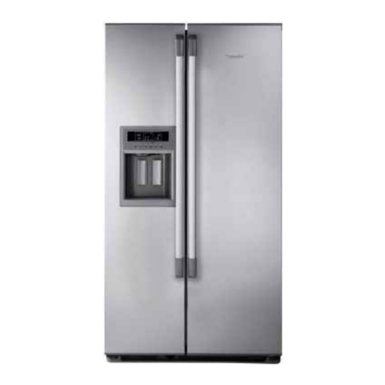
Indesit Company STAR RATING UK and EU freezers and refrigerators with freezer compartments are star rated with regard to their capacity to store or freeze food. The temperatures for the freezer compartment relating to these star ratings are as follows: Maximum Minimum Storage Time for... - Page 5 Indesit Company MODEL INTRODUCTION The models included in this manual are 1774 mm high Side by Side fridge and freezer, one compressor Frost Free appliances. There are two different ranges of the same model, the first range was first introduced during March 2010 and the second range during September 2011. All models are similar with regard to the furniture design, refer to Technical Specification Pages 6 and 7 for the models, colour variants and specifications.
-
Page 6: Introduction
Indesit Company SPECIFICATIONS Commercial Introduction Model Colours Manufactured Code Date MSZ906DF Black 71630 Italy March 2010 MSZ900DF Silver 71629 Italy March 2010 MSZ902DF Stainless Steel 71622 Italy March 2010 MSZ900NDFUK Silver 76246 Italy Sept. 2011 MSZ902NDFUK Stainless Steel 76244 Italy Sept. - Page 7 Indesit Company TECHNICAL DATA: Power Supply Voltage: 220/240 V Power Supply Frequency: 50 Hz Mains Water Supply: Min. 1.38 bar Max. 8.27 bar Freezer Lamp: T-Click 40W 220V - 240V Fridge Lamp: T-Click 40W 220V - 240V ENERGY Energy Class: Power Consumption: 1.39 kWh/24hr Annual Consumption:...
-
Page 8: Appliance Dimensions
Indesit Company DIMENSIONS APERTURE MEASUREMENTS PLAN VIEW (Measurements below are the minimum requirement in mm. (With door open 90° and fully) Dimensions include the 10 mm space required on both sides, back and above) 1064 1137 1754 PLAN VIEW DIMENSIONS (mm) Door opening with Handle (Fridge Side, door in relaxed natural open position. -
Page 9: Removing The Appliance Furniture
Indesit Company REMOVING THE REFRIGERATOR & FREEZER FURNITURE Removing the Fridge and Freezer Shelves 1. Pull the shelf out until it reaches its stop point then lift the shelf from the front to remove it. 2. NOTE: - For the easiest recommended removal of some fridge shelves and drawers, lift the front end up to nearly a vertical position whilst pushing the fridge door fully open. -
Page 10: Detailed Views
Indesit Company 2010 DF MODELS DETAILED VIEW Refrigeration Compartment Freezer Compartment A. Interior light located within the damper M. Automatic icemaker located behind cover housing/light box N. Interior light located on the back wall B. Shelves O. Icemaker emitter (left liner) C. - Page 11 Indesit Company 2011 NDF MODELS Refrigeration Compartment Freezer Compartment A. Inside light P. Automatic ice maker B. Shelves Q. Inside light C. Shelf - drawer lid R. Glass shelves / racks (depending on model) D. Snack drawer (depending on model) S.
-
Page 12: Water Filter
Indesit Company WATER FILTER REMOVAL OF THE FILTER Locate the water filter cartridge cap in the base plinth grille below the freezer compartment door. Rotate the cap counter clockwise to a vertical position (¼ turn) and pull the cap and filter cartridge from the filter housing out through the base grille. -
Page 13: Ice Maker Operation & Water Flow System
Indesit Company ICE MAKER OPERATION - 2010 DF MODELS To operate ensure: • The appliance has reached -9°C for a minimum of 2 hours. • Crushed ice or cubed ice mode is selected on the user control display. • The appliance has been on for approximately 12-24 hours at initial start up. A. - Page 14 Indesit Company C. Ice Harvesting. The harvesting process begins when the Ice Maker thermostat closes and signals that the harvest temperature has been reached. The closed thermostat applies power to the ice maker motor and to the heater. As the heater melts the outer layer of the ice, the motor rotates a rake (rake in blue in Fig.
- Page 15 Indesit Company ICE MAKER OPERATION - 2011 NDF MODELS ICE MAKER SANKYO IDI2 (FIG. 4) OPERATION - 2011 NDF MODELS: Fig. 4 To operate ensure: • The appliance has reached -10°C for a minimum of 2 hours. • Crushed ice or cubed ice mode is selected on the user control display.
- Page 16 Indesit Company To avoid water overflow, the main module will switch OFF the relay K002 if the ice valve feedback lasts more than 20 seconds. The Icemaker system will then be switched OFF until the following points will be satisfied: 1) The power has been removed (Power-OFF) 2) The main power has been re-applied (Power-UP) During this failure condition the main power module will...
- Page 17 Indesit Company ICE SOLENOID WATER VALVE MANAGEMENT (2010 DF MODELS): The icemaker water solenoid valve will be automatically controlled and driven by the Icemaker. The flow rate for the icemaker water valve:1.13 litres per minute (140cc per 7.5 seconds +11cc –17cc) Supply voltage (nominal): Motor power dissipation: Ice production per 24 Hours:...
- Page 18 WATER FLOW SYSTEM ICEMAKER INTERFACE FRONT DISPENSER FILTER HOUSING WATER INLET REAR FILL water flow.ai WATER RESERVOIR VALVE LOCATED IN FRIDGE Underneath the ice and water dispenser is a grille and sump to catch any spillage that may occur. This is not a drain.
- Page 19 Indesit Company Ice Maker Circuit through the Display, Main Control, Emitter and Receiver Boards DF 2010 Models Receiver This is Pole 1 of 10 for Heater De-Frost NAR 120V version Pole 6 of 10 Pole 4 of 10 (IR_Line) (Line/Phase) n.c.
- Page 20 Indesit Company WIRING FOR THE SANKYO ICEMAKER IDI2 (2011 NDF MODELS) NOTE: - When the plus pole is connected with terminal 8 and the minus pole is connected with terminal 7, the tray will rotate. Service Manual UK English 20 of 61...
-
Page 21: Power Module Parameters
Indesit Company POWER MODULE Parameters Parameters set in the module memory control the appliance functions. The minimum and maximum values for temperature are preset in the module memory. Sensors monitor temperature and the values are registered in the module. Where the sensor values are outside the presets a Parameter Values particular function will start or stop. -
Page 22: Power Module Parameters
Indesit Company POWER MODULE Parameters DEFROST HEATING ELEMENTS • Compressor ON time since the last defrost cycle. 8 hours, but the start time will reduce dependant on door opening times. Defrost Heating Elements - • The appliance is plugged in and switched on. The parameters utilised to start the defrost cycle are as follows: •... -
Page 23: Display Panel Functions & Descriptions
Indesit Company DISPLAY PANEL FUNCTIONS & DESCRIPTIONS BUTTON DESCRIPTION FUNCTION Freezer To change the desired temperature press this button until the Temperature display shows the temperature required (Icon 1). This will increase Adjust / Select by increments of 1°C in the range of from -24°C up to -18°C with a audible beep with each selection, then with a double beep it skips from -18°C down to -24°C. - Page 24 Indesit Company Holiday This function deactivates the refrigeration compartment if the user is going away for a period of time. When the icon (7) comes on in the right hand fridge section of the display the fridge temperature will be replaced by a dash (Fig. 9.) When activated perishable food should be removed from the fridge and the door kept closed.
-
Page 25: Display Panel Functions & Descriptions
Indesit Company DISPLAY PANEL FUNCTIONS & DESCRIPTIONS DISPLAY DESCRIPTION FUNCTION ICON Temperature or Displays the freezer temperature required set by the user by Fault Code pressing button A Display icon 1 can also show an alarm code (see Pages 31 & 32 for Alarm Conditions). The acoustic alarm will also -18°C be sounding if there is an alarm code. - Page 26 Indesit Company Crushed Ice Mode Press button C until this icon lights up on the display. Selected When pushing the ice dispensing paddle it operates the auger and blades in a clockwise direction so the jagged side of the blades crush the ice and then pushes the crushed ice down the chute.
- Page 27 Indesit Company Black Out Safe This icon will blink if the freezer compartment temperature has risen above - 9°C during the black out period. The user should not re-freeze any thawed food and should not restock freezer until optimal temperature has been reached. Freezer icon 1 shows the warmest temperature that the freezer reached while in Black Out.
-
Page 28: Component Functions
Indesit Company COMPONENT FUNCTIONS General Information The power module is made up of a number of smaller individual modules (sections), each one controlling a functional component. The modules are linked together when required to control a particular function or functions. The linking of the individual modules is optional and therefore allows for each module to be switched ON or OFF, this is determined from the data stored or collected by the modules and the results of module comparisons. -
Page 29: Component Functions
Indesit Company COMPONENT FUNCTIONS Stepper Motor Characteristics (for the damper and dispenser motors) Stepper motors operate differently from normal DC motors, which rotate when voltage is applied to their terminals. Stepper motors, on the other hand, effectively have multiple "toothed" electromagnets arranged around a central gear-shaped piece of iron. - Page 30 Indesit Company Ice Dispenser - Stepper Motor This stepper motor allows the ice to be dispensed by opening and closing the chute when the ice dispenser paddle is activated, see Fig. 10. The chute will stay open for approximately 10 seconds to prevent ice from getting trapped.
-
Page 31: Alarm Conditions, Temperature Tables & Auto Test
Indesit Company ALARM CONDITIONS The User Interface Module detects any failures or issues within the appliance. When a failure or issue is detected the user display will: - 1. Activates the audible alarm and/or 2. Brings on a blinking icon and/or 3. - Page 32 Indesit Company ALARM CODES COMPARTMENT ALARM DISPLAY DESCRIPTION DISPLAY CODE BLINKING Freezer display "U U" Wrong User Interface Module. User Interface Module & Main Control Module is not communicating. Freezer display "S F" Freezer Thermistor (sensor). Note: the appliance still runs at the default set parameters.
- Page 33 Indesit Company TEMPERATURE TABLES REFRIGERATION DAMPER CONDITIONS NTC sensor (thermistor) is Refrigerator located in the refrigerator Damper ON (°C) Damper OFF (°C) Display (°C) compartment to control the temperature by means of the evaporator fan and the damper. If conditions differ, check the damper and vent for ice blockages. If the fridge sensor fails the main board preset parameters will operate the Evaporator Fan for 15 minutes together with opening of the damper and then turn it OFF for 30 minutes whilst closing the...
- Page 34 Indesit Company AUTO TEST NOTE: - Before using the AUTO-TEST it is advisable to check the correct operation of the temperature LEDs in both fridge and freezer display, as these LEDs are used for signalling possible malfunctions. Ensure the Super Freeze or Holiday modes have not been selected before starting the AUTO-TEST. STEP 1: If the appliance has been connected to the mains power for more than 15 minutes, disconnect it and wait 40 seconds before reconnecting it back to the mains supply.
- Page 35 Indesit Company FAULT CODES TEMPERATURE DISPLAY AUTO-TEST FAULT CODE Fridge (explanations) flashing Check alternatively Relay K008 on module (for Damper) flashing alternatively Check Evaporator Defrost Heater - resistance can be obtained from power module 12PIN block term 1 & 16PIN block term 1 flashing alternatively Check Fridge Sensor (thermistor) flashing alternatively...
-
Page 36: Ice Maker & Ice Dispensing Troubleshooting
SIDE BY SIDE ICE MAKER DIAGNOSTICS ICE MAKER TROUBLESHOOTING Press the ICE Is the Ice Maker MODE button The water valve could be stuck at switched on? (refer to Page 26 (2010 DF Models) water fill position. Check Ice Maker (One of the ICE button C) on the Carry out... - Page 37 ICE DISPENSING TROUBLESHOOTING (2010 DF MODELS) Ensure the customer is using the internal Ice Maker to product ice and they have not added brought in ice to the Turn on Ice Mode Also see previous Page container. Ice made in the internal ice maker is of the on display panel 36 for Ice Maker proper size and shape for the dispenser and must be the...
- Page 38 OPTICS DIAGNOSTICS MODE TEST - ICE MAKER TROUBLESHOOTING (2010 DF MODELS) Follow checks on Pages 26 and 37 for Ice Maker and Ice Dispensing Troubleshooting Optics Test. The Ice Maker may be in ‘Harvest Open the Ice Maker flap. On the user board deselect ice mode. Mode’...
-
Page 39: Air Flow
Indesit Company AIR FLOW COMPRESSOR AND CONDENSER COMPARTMENT The condenser fan is mounted at the rear near the compressor and draws air from the room through the right side of the front lower grille (A), through the condenser (B), around the compressor (C) where it exits out of the rear panel (D) but mainly passes over the dissipator to evaporate the defrost water (E) and finally exits out through the left side of the front lower grille. -
Page 40: Air Flow
Indesit Company AIR FLOW FRIDGE AND FREEZER INTERIOR COMPARTMENTS FREEZER The freezer evaporator is mounted just above the evaporator assembly (F). The fan draws air up through the evaporator where it is cooled (G) and blows into the top duct panel where it is channelled out through outlet ports (H). -
Page 41: Thermistor (Ntc) Sensor Location
Indesit Company THERMISTOR (NTC) SENSOR LOCATION Two sensors are used in these models, the approximate locations are as follows: - 1. Freezer Air Sensor - Located in the left liner wall just below the ice maker. 2. Fridge Air Sensor - Located in the centre of the rear liner wall of the fridge. Temperature Accuracy Temperature... -
Page 42: Servicing & Dismantling Instructions
Indesit Company SERVICING & DISMANTLING INSTRUCTIONS Before commencing any work refer to the Safety Notes at the beginning of this manual. All necessary precautions must be taken to prevent damage to the premises and the appliance. The appliance must be disconnected from the mains electricity supply. Where necessary, food and containers should be removed and stored according to the customer requirements. - Page 43 Indesit Company E. ICEMAKER - 2010 DF MODELS Located in the top part of the freezer compartment. Remove the top freezer shelf for ease of access to the small screw on the underside of the icemaker (Fig. 14). Tape down the sensor emitter flap located on the left side of the freezer liner (Fig. 15). Open the ice maker flap cover fully to access the hinge pins.
- Page 44 Indesit Company AUGER, ICE CUBE CONTAINER / BUCKET AND ICE CRUSHER MOTOR Remove the ice cube container from the inner freezer door by locating its handle on the right under side of the bucket. Squeeze the handle to release the container from its secured position and lift the container off the ice crusher motor cover.
- Page 45 Indesit Company EVAPORATOR Remove the components as in H. Disconnect the 2-pin connector for the fan motor. Remove the two screws securing the plastic housing to the rear wall. Lift the evaporator metal heat shield upward slightly to release it from the retaining clip on the rear wall.
- Page 46 Indesit Company S. PLASTIC DEFROST WATER EVAPORATION / DISSIPATOR TRAY Remove the components as in P and R. The tray can now be removed from the right rear of the appliance. CONDENSER FAN MOTOR (Refer to section ZE on Page 49 for water tube removal) Release the 2 screws securing the lower plinth/grille beneath the doors.
- Page 47 Indesit Company Withdraw the dispenser towards you to remove. Fig. 18 Fig. 17 X. DISPLAY PCB MODULE Remove the control panel interface as in W 1-4 above. Place dispenser box on its front on a work surface, remove the three screws to remove the display board.
- Page 48 Indesit Company ZA. DRINKS DISPENSER WATER FEED PIPE/TUBE (Refer to section ZE on Page 49 water tube removal) Remove the lower plinth/grille (2 screws). Disconnect the water tube from left lower side behind the removed plinth. Remove the dispenser grille from below the dispensing levers and remove the 2 screws. Ease the control panel / dispenser box away from clips.
- Page 49 Indesit Company ZE. WATER TUBES/HOSES - QUICK COUPLING (where possible observe best hygiene practises when handling drinking water tubes/components to avoid contamination) The water tubes/hoses/pipes within this appliance are fitted with a quick coupling connection. They have a Quick Connect valve which has Push-in-tube connections. Pencil mark (approx.12mm) the tube insertion length before removing (if not already marked).
-
Page 50: Boards
Indesit Company BOARDS MAIN BOARD Pin 1 (main line) Pin 2 (compressor load) Pin 3 (main neutral) RECEIVER BOARD 2010 DF MODELS Pin 1 (to emitter pin 3) Pin 2 (to emitter pin 2) Pin 2 (line) Pin 4 (line to icemaker pin 3) Pin 5 Pin 5 (door switch feed-back) Pin 7 (not used) -
Page 51: Compressor Connection Chart
Indesit Company COMPRESSOR CONNECTION CHART EMBRACO COMPRESSOR TERMINAL BLOCK 1 ~ COMMON (Overload) L ~ LIVE (line) & Capacitor ~ EARTH S ~ CAPACITOR N ~ NEUTRAL SCHEMATIC VIEW OF TERMINAL BLOCK TERMINAL COLOUR DESCRIPTION BLACK COMMON (OVERLOAD) BROWN LIVE & RUN CAPACITOR GREEN/YELLOW EARTH BLUE... -
Page 52: Power Module Edge Connections
POWER MODULE EDGE CONNECTIONS - 2010 DF MODELS Pin 1/6. Water Valve CN05 CN06 CN06 CN04 Pin 2/6. Ice Valve Pin 1/4. Fridge Probe Pin 1/12. Bimetallic Feed Back Pin 7/12. Damper Load Pin 1/16. Freezer Line Pin 3/6. Condenser Fan Pin 2/4. - Page 53 POWER MODULE EDGE CONNECTIONS - 2011 NDF MODELS 16 Pin 12 Pin Block Block 6 Pin 10 Pin Block Block 4 Pin Block 10 Pin 6 Pin Block Block 16 Pin Block 12 Pin Block...
-
Page 54: Theoretical Wiring Diagrams
WIRING DIAGRAM - 2011 NDF MODELS KEY: fd-bk = Feedback... - Page 55 THEORETICAL WIRING DIAGRAM - 2010 DF MODELS Plug USER INTERFACE Main Connector Block Refrigerator Compressor P.T.C. Motor Overload Compressor H4 Bimetal + Thermofuse Damper Running Capacitor Evaporator Door Heater Heater Anti Condensation Heater Electric Motor (Auger) M1 Dispenser Chute Stepper Motor Fan Motor Push Switch Lamp...
-
Page 56: Installation Instructions
Indesit Company INSTALLATION INSTRUCTIONS INTRODUCTION The model you are installing may differ slightly with respect to some descriptions in this installation, since this covers several models. Install the appliance in a dry and well-ventilated place. Avoid locations in direct sunlight or near a source of heat (oven, heating, etc.). If this cannot be avoided, install the appliance respecting the following minimum distances: Coal or paraffin stoves: 300 mm Electric and/or gas stoves: 30 mm... - Page 57 Indesit Company INSTALLATION INSTRUCTIONS LEVELLING THE APPLIANCE 2010 DF models have two front and two rear wheels at the base of the product on each side that can be adjusted (see Figure A), or four wheels of which only the two front wheels can be adjusted (see Figure B).
- Page 58 Indesit Company INSTALLATION INSTRUCTIONS REMOVING THE FREEZER DOOR (A) REMOVING THE REFRIGERATOR DOOR (B) Service Manual UK English 58 of 61...
- Page 59 Indesit Company INSTALLATION INSTRUCTIONS MOUNTING THE FREEZER DOOR (C) MOUNTING THE REFRIGERATOR DOOR (D) Service Manual UK English 59 of 61...
- Page 60 Indesit Company INSTALLATION INSTRUCTIONS HORIZONTAL ALIGNMENT OF FREEZER AND REFRIGERATOR DOORS (E) VERTICAL ALIGNMENT OF FREEZER AND REFRIGERATOR DOORS (F) Service Manual UK English 60 of 61...
- Page 61 Indesit Company Service Manual UK English 61 of 61...
Need help?
Do you have a question about the MSZ900DFUK and is the answer not in the manual?
Questions and answers