Advertisement
Quick Links
JY997D40801C
Side
JAPANESE
A
Side
ENGLISH
B
FX
-8EYR-S-ES/UL
2N
HARDWARE MANUAL
Manual Number
JY997D40801
Revision
C
Date
December 2017
This manual describes the part names, dimensions, mounting, and specifications
of the product. Before use, read this manual and the manuals of all relevant
products fully to acquire proficiency in handling and operating the product. Make
sure to learn all the product information, safety information, and precautions.
Store this manual in a safe place so that it can be taken out and read whenever
necessary. Always forward it to the end user.
Registration:
Phillips is a registered trademark of Phillips Screw Company.
The company and product names described in this manual are registered
trademarks or the trademarks of their respective companies.
Effective December 2017
Specifications are subject to change without notice.
Safety Precaution
(Read these precautions before use.)
If the equipment is used in a manner not specified by the manufacturer, the
protection provided by the equipment may be impaired.
This manual classify the safety precautions into two categories:
and
.
Indicates that incorrect handling may cause hazardous
conditions, resulting in death or severe injury.
Indicates that incorrect handling may cause hazardous
conditions, resulting in medium or slight personal injury
or physical damage.
Depending on circumstances, procedures indicated by
linked to serious results.
In any case, it is important to follow the directions for usage.
Associated Manuals
Manual name
Manual No.
Description
FX
Series
JY997D31301
E x p l a i n s F X
S e r i e s P L C
3G
3 G
User's Manual
MODEL CODE:
specification details for I/O, wiring,
- Hardware Edition
09R521
installation, and maintenance.
FX
Series
JY997D16501
E x p l a i n s F X
S e r i e s P L C
3U
3 U
User's Manual
MODEL CODE:
specification details for I/O, wiring,
- Hardware Edition
09R516
installation, and maintenance.
FX
Series
JY997D28701
E x p l a i n s F X
S e r i e s P L C
3UC
3 U C
User's Manual
MODEL CODE:
specification details for I/O, wiring,
- Hardware Edition
09R519
installation, and maintenance.
JY992D66301
E x p l a i n s F X
S e r i e s P L C
2 N
FX
2N
MODEL CODE:
specification details for I/O, wiring,
HARDWARE MANUAL
09R508
installation, and maintenance.
Explains FX
(D/UL) Series PLC
2NC
FX
2NC
(D/UL)
JY992D87201
specification details for I/O, wiring,
HARDWARE MANUAL
installation, and maintenance.
JY992D76401
Explains FX
2NC
(DSS/DS) Series
FX
(DSS/DS)
2NC
MODEL CODE:
PLC specification details for I/O,
HARDWARE MANUAL
09R509
wiring, installation, and maintenance.
JY992D89301
E x p l a i n s F X
S e r i e s P L C
1 N
FX
1N
MODEL CODE:
specification details for I/O, wiring,
HARDWARE MANUAL
09R511
installation, and maintenance.
How to obtain manuals
For the necessary product manuals or documents, consult with the Mitsubishi
Electric dealer from where you purchase your product.
Side
B
Certification of UL, cUL standards
FX
2N
-8EYR-S-ES/UL units comply with the UL standards (UL, cUL).
UL, cUL File Number: E95239
Regarding the standards that comply with the main unit, please refer to either the FX
series product catalog or consult with your nearest Mitsubishi product provider.
Compliance with EC directive (CE Marking)
This product complies with EC directive, however, this document does not guarantee
that a mechanical system including this product will comply with EC directive.
Compliance to EMC directive and LVD directive for the entire mechanical module
should be checked by the user/manufacturer. For more information please consult with
your nearest Mitsubishi product provider.
Caution for EC Directive
• Please use the programmable controllers while installed in conductive shielded
control panels under a general industrial environment.
• Programmable controllers are open-type devices that must be installed and used
within conductive control panels. Please secure the control box lid to the control box
(for conduction). Installation within a control box greatly affects the safety of the
system and aids in shielding noise from the programmable controller.
• For the control panel, use the product having sufficient strength, fire protectiveness
and shielding property to an installation environment.
• 24 V DC of the power supply must be supplied from the circuit double/reinforced
insulated from the main power supply (MAINS).
Caution for compliance with the LVD directive (EN61010-2-201:2013)
• To an external connection port other than AC power supply terminal and AC input/
output terminal, connect the circuit separated from a dangerous voltage by a
double/reinforced insulation.
• Between the commons having the adjacent relay output terminals, if an external
power supply is higher than 120 V AC, the insulation is basic. Therefore, when
using 120 V AC or higher external power supply and 30 V DC/AC or lower external
power supply between the adjacent commons, do not handle 30 V DC/AC or lower
external power supply as a touchable part, (When handling 30 V DC/AC or lower
external power supply as a touchable part, add a basic insulation.)
• Do not wire two or more crimp terminals to one terminal. (If the wiring with two or
more wires is needed, take an appropriate action such as adding an external
terminal.)
• For crimp terminals to be used for the wiring applied with 30 V AC or higher, use the
products with insulating sleeves.
• Cutoff device such as a breaker or a circuit protector should be installed in
accordance with the following precautions.
-
Use EN60947-1 or EN60947-3 standards.
-
Place the cutoff device so that it can be operated easily.
-
Specify that the cutoff device is for this equipment.
*1 For the time of compliance with the LVD directive (EN61010-2-201:2013), refer
may also be
to the manual of the PLC to be connected.
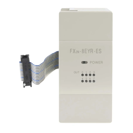
1. Outline
1.1 Outline
The FX
-8EYR-S-ES/UL output extension block (hereinafter called FX
2N
ES/UL) is a extension block to connect the FX
3G
FX
Series main units.
1NC
FX
-8EYR-S-ES/UL has 8 points relay outputs, and all output terminals have
2N
separate reference terminals (Commons).
1.2 Communication Function
Check if the following product and items are included in the package:
Included Items
FX
-8EYR-S-ES/UL
1 unit
2N
Input/output number label
1 sheet
Dust proof protection sheet
1 sheet
Manuals (Japanese version, English version)
1 manual each
1.3 External Dimensions, Part Names
2- 4.5 mounting holes
[1] [2] [3] [4]
[5]
*1
40 (1.58")
Without cover
[9]
[10]
Unit: mm (inches)
MASS (weight): Approx. 0.3 kg (0.66 lbs)
No.
Name
[1]
Extension cable
[2]
Top cover
[3]
Power LED
[4]
Direct mounting hole (mounting screw: M4 screw)
[5]
Output LED
[6]
Nameplate
DIN rail mounting groove
[7]
(DIN rail: DIN46277, 35mm (1.38") width)
[8]
DIN rail mounting hook
[9]
Output terminal block (M3 terminal screw)
[10]
Extension connector
2. General specifications and Installation
DESIGN
-8EYR-S-
2N
PRECAUTIONS
/FX
/FX
/FX
/FX
/FX
/
3U
3UC
2N
2NC
1N
• Make sure to have the following safety circuits outside the PLC to ensure
safe system operation even during external power supply problems or PLC
failure.
Otherwise, malfunctions may cause serious accidents.
1) Most importantly, have the following: an emergency stop circuit, a
protection circuit, an interlock circuit for opposite movements (such as
normal vs. reverse rotation), and an interlock circuit (to prevent damage
to the equipment at the upper and lower positioning limits).
2) Note that when the PLC CPU detects an error, such as a watchdog timer
error, during self-diagnosis, all outputs are turned off. Also, when an error
that cannot be detected by the PLC CPU occurs in an input/output control
block, output control may be disabled.
External circuits and mechanisms should be designed to ensure safe
machinery operation in such a case.
3) Note that when an error occurs in a relay output device, the output could
be held either on or off.
For output signals that may lead to serious accidents, external circuits
and mechanisms should be designed to ensure safe machinery operation
in such a case.
[6]
DESIGN
PRECAUTIONS
• Do not bundle the control line together with or lay it close to the main circuit
[7]
or power line. As a guideline, lay the control line at least 100mm (3.94") or
more away from the main circuit or power line.
Noise may cause malfunctions.
• Install module so that excessive force will not be applied to the terminal
blocks.
Failure to do so may result in wire damage/breakage or PLC failure.
[8]
INSTALLATION
PRECAUTIONS
9 (0.36")
• Make sure to cut off all phases of the power supply externally before
87 (3.43")
attempting installation or wiring work.
Failure to do so may cause electric shock or damage to the product.
INSTALLATION
PRECAUTIONS
• Use the product within the generic environment specifications described in
PLC main unit manual (Hardware Edition).
Never use the product in areas with excessive dust, oily smoke, conductive
dusts, corrosive gas (salt air, Cl
vibration or impacts, or expose it to high temperature, condensation, or rain
and wind.
If the product is used in such conditions, electric shock, fire, malfunctions,
deterioration or damage may occur.
• Do not touch the conductive parts of the product directly.
Doing so may cause device failures or malfunctions.
• Install the product securely using a DIN rail or mounting screws.
• Install the product on a flat surface.
If the mounting surface is rough, undue force will be applied to the PC board,
thereby causing nonconformities.
• When drilling screw holes or wiring, make sure that cutting and wiring debris
do not enter the ventilation slits of the PLC.
Failure to do so may cause fire, equipment failures or malfunctions.
• Be sure to remove the dust proof sheet from the PLC's ventilation slits port
when installation work is completed.
Failure to do so may cause fire, equipment failures or malfunctions.
• Connect the extension cables securely to their designated connectors.
Loose connections may cause malfunctions.
• When a dust proof sheet is supplied with module, keep the sheet applied to
the ventilation slits during installation and wiring work.
• To prevent temperature rise, do not install the PLC on a floor, a ceiling or a
vertical surface. Install it horizontally on a wall.
• Keep a space of 50 mm or more between the module main body and another
device or structure. Install the module as far away as possible from high-
voltage lines, high-voltage devices and power equipment.
Failure to do so may cause fire, equipment failures or malfunctions.
, H
S, SO
, or NO
), flammable gas,
2
2
2
2
Notes
Advertisement

Related Manuals for Mitsubishi Electric FX2N-8EYR-S-ES/UL


Summary of Contents for Mitsubishi Electric FX2N-8EYR-S-ES/UL
- Page 1 JY997D40801C Side Side JAPANESE Side ENGLISH Certification of UL, cUL standards 1. Outline 2. General specifications and Installation -8EYR-S-ES/UL units comply with the UL standards (UL, cUL). 1.1 Outline DESIGN UL, cUL File Number: E95239 The FX -8EYR-S-ES/UL output extension block (hereinafter called FX -8EYR-S- PRECAUTIONS Regarding the standards that comply with the main unit, please refer to either the FX...
- Page 2 Power supply specification is the same as the FX -8EYR(-ES/UL). When there nor does it confer any patent licenses. Mitsubishi Electric Corporation cannot be • The product is a precision instrument. During transportation, avoid impacts is not a description in the PLC manual, please select in the same way as the...
- Page 3 Power supply specification is the same as the FX -8EYR(-ES/UL). When there nor does it confer any patent licenses. Mitsubishi Electric Corporation cannot be is not a description in the PLC manual, please select in the same way as the held responsible for any problems involving industrial property rights which may •...