Advertisement
Quick Links
Advertisement

Related Manuals for Mitsubishi Electric FX2N-16


Summary of Contents for Mitsubishi Electric FX2N-16
- Page 1 HARDWARE MANUAL SERIES PROGRAMMABLE CONTROLLERS...
- Page 2 Si lors de l’installation des incertitudes persistent, n’hésitez pas à consulter un électricien compétent, qualifié et formé à l’utilisation des normes électriques locales et nationales. Contactez le représentant le plus proche de MITSUBISHI ELECTRIC si la manipulation ou l’utilisation des API de la série FX vous pose des problèmes.
- Page 3 All examples and diagrams shown in this manual are intended only as an aid to understanding the text, not to guarantee operation. MITSUBISHI ELECTRIC will accept no responsibility for actual use of the product based on these illustrative examples.
- Page 4 Series Programmable Controllers Series Programmable Controllers Hardware Manual Manuel du matériel Hardware-Handbuch Manuale hardware Manual de Hardware Manual number: JY992D66301 Manual revision: Date: APRIL 1999...
- Page 5 Series Programmable Controllers Guidelines for the safety of the user and protection of the FX This manual provides information for the installation and use of the FX . The manual has been written to be used by trained and competent personnel. The definition of such a person or persons is as follows;...
- Page 6 Series Programmable Controllers Directives de sécurité pour l’utilisateur et mesures de protection pour les API de la série FX Le présent manuel contient des informations concernant l’installation et l’utilisation des API de la série FX . Ce manuel a été établi à l’intention d’un personnel formé et compétent.
- Page 7 Series Programmable Controllers Sicherheitsrichtlinien für den Anwender und Schutzmaßnahmen für die FX -SPS Dieses Handbuch enthält Informationen zur Installation und zum Einsatz der FX SPS. Das Handbuch wurde für geschultes und kompetentes Personal erstellt. Hierbei wird für die Qualifizierung folgende Definition zugrunde gelegt: Jeder Techniker, der Anlagen der Automatisierungstechnik unter Einbeziehung des Produktes plant, projektiert und errichtet, sollte diesbezüglich ausreichende Kenntnisse besitzen.
- Page 8 Series Programmable Controllers Direttive di sicurezza per l’utente e misure di sicurezza per il PC FX Il presente manuale contiene informazioni per l’installazione e l’impiego del PC FX Il manuale è destinato a personale addestrato e competente. Per la qualifica del personale viene considerata la seguente definizione: Ogni tecnico responsabile della pianificazione, progettazione e costruzione di impianti di automazione che impiega il prodotto descritto nel presente manuale dovrebbe avere conoscenze adeguate in merito.
- Page 9 Series Programmable Controllers Instrucciones de seguridad para el usuario y medidas de protección para la unidad PC-FX Este manual comprende las informaciones correspondientes para la instalación y el uso de la unidad PC-FX . El manual ha sido elaborado para un empleo por personal competente y capacitado.
- Page 10 Series Programmable Controllers The following variations of the FX PC conform to the identified standards; Les types d’API de la série FX suivants sont conformes aux normes et critères d’homologation mentionnés. Die folgenden Typen der FX -SPS stimmen mit den aufgeführten Normen und Zulassungskriterien überein.
- Page 11 Series Programmable Controllers viii...
- Page 12 Series Programmable Controllers Introduction Introduction Introduction Einleitung Introduzione Introducción Terminal Occupation Klemmen- Assegnazione Ocupaciones Layouts des bornes belegungen dei morsetti de bornas Installation Installation Installation Installazione Instalación Notes Alimentation Spannungs- Alimentazione Alimentación Power supply en tension versorgung della tensione de tensión Inputs Entrées Eingänge...
- Page 13 Series Programmable Controllers Introduction 1 - 2...
- Page 14 Series Programmable Controllers Introduction Introduction This manual covers the hardware installation instructions for the following programmable controller (PC) product ranges; base and extension units extension and special function blocks Introduction Le présent manuel comprend la description de l’installation pour les automates programmables (API) suivants: Appareils de base et appareils d’extension FX Modules d’extension et modules spéciaux FX...
- Page 15 Series Programmable Controllers Introduction Table: 1.1 AC base unit Appareils de base AC-Grundgerate Apparecchi base AC Unidades base CA INPUTS OUTPUT TYPE DIMENSIONS WEIGHT POWER MODEL SUPPLY TYPE RELAY TRANSISTOR mm(inch) kg (lbs) 0.60 (5.12) (1.3) 0.65 (5.9) (1.4) 0.85 24V DC MT-ESS/UL (7.2)
- Page 16 Series Programmable Controllers Introduction Table :1.3 Powered extension units Appareils d’extension alimentés en tension Spannungsversorgte Erweiterungsgeräte Apparecchi di ampliamento con alimentazione di tensione Unidades de ampliación con alimentación de tensión INPUTS OUTPUT TYPE DIMENSIONS WEIGHT POWER MODEL SUPPLY TYPE RELAY TRANSISTOR mm(inch) kg (lbs)
- Page 17 Series Programmable Controllers Introduction Figure: 1.1 Dimensioned unit Dimensions Abmessungen Dimensioni Dimensiones (13.78) 87 (3.42) (5.11) (3.54) DIN rail : 35mm (1.38) UNITS: mm (inches) Figure: 1.2 Extension block dimensions Dimensions des modules d’extension Abmessungen der Erweiterungsmodule Dimensioni dei moduli di ampliamento Dimensiones de los módulos de ampliación (2.76) 87 (3.42)
- Page 18 Series Programmable Controllers Introduction Table: 1.5 Special function Módulos especiales blocks Modules spéciaux Sondermodule Moduli speciali NUMBER POWER SUPPLY DIMENSIONS WEIGHT OF I/O MODEL DESCRIPTION Internal External mm (inches) kg (lbs) 5v DC 24v DC -4DA Digital to analog converter 30 mA 200 mA -4AD...
- Page 19 Series Programmable Controllers Introduction Unit Accessories Each powered extension unit comes with; 1 I/O label kit and a 55mm (2.17 inch) extension cables. Each extension and special function block comes with an I/O label kit. Accessoires d’un appareil Etendue de la fourniture d’un appareil d’extension alimenté en tension: 1 jeu d’auto- collants E/S et le câble d’extension de 55 mm de long.
- Page 20 Series Programmable Controllers Introduction Model name Désignation des types d’ap- pareils. Gerätetypenbezeichnung Designazione dei modelli. Designación del tipo de unidad Table: 1.8 Description Typenbeschreibung Descrizione Descripción Model table des types dei modelli del tipo PC type, FX, Série d’API: FX, SPS-Serie: FX, Serie di PC: FX, Serie PC: FX,...
- Page 21 Series Programmable Controllers Introduction Figure: 1.3 Model name 16 M R-ES/ UL Désignation des types d’appareils. Typenbezeichnung Modello. Designación del tipo Serial numbers Numéro de série Seriennummer Numero di serie Número de serie Table: 1.9 Notes on serial Explication du Erläuterung der Spiegazione del Aclaración del...
- Page 22 Series Programmable Controllers Introduction Construction du système Configuration Struttura del sistema Systemaufbau Configuración del sistema Figure: 1.5 Schematic system Représentation schématique de la construction du système Schematischer Systemaufbau Struttura schematica del sistema Configuración esquemática del sistema FX2N-32ER-ES/UL FX-EEPROM-4 FX-EPROM-8 FX2N-48ER-ES/UL FX-EEPROM-8 FX-RAM-8 FX2N-32ET-ESS/UL FX-EEPROM-16...
- Page 23 Series Programmable Controllers Introduction Table: 1.10 Configuration Description de la Konfigurations- Descrizione della Descripción de la notes configuration beschreibung configurazione configuración Unidad base de MPU - base unit Apparecchio base Appareils de base API SPS-Grundgerät mando de memoria (Main Processing Unit) programable (PC) Apparecchi di Unidades de...
- Page 24 Series Programmable Controllers Introduction 1.5.1 Rules Max. 8 special function blocks per system. Check the loading on the 5V bus. Consumption values for special function blocks can be found in table1.5. For maximum available current see the table below . Check the loading on the 24V DC service supply.
- Page 25 Series Programmable Controllers Introduction Règles de base relatives à la construction du système Huit (8) modules spéciaux au maximum sont autorisés par système. Vérifiez la charge au bus de 5 Volt. Pour la valeur de consommation de courant des modules spéciaux, vous pouvez consulter le tableau 1.5. L’intensité maximale admis- sible est indiquée dans la partie inférieure du tableau.
- Page 26 Series Programmable Controllers Introduction X030 - BLOCK Figure: 1.6 X000 - X027 X037 No. 0 OUT 0 COM X0 4 5 6 22 23 24 25 26 POWER 12 13 POWER POWER POWER POWER BATT.V PROG.E No. 0 4 5 6 22 23 24 25 26 CPU.E 12 13...
- Page 27 Series Programmable Controllers Introduction 1 - 16...
- Page 28 Series Programmable Controller Terminal Layout Introduction Introduction Einleitung Introduzione Introducción Terminal Occupation Klemmen- Assegnazione Ocupaciones Layouts des bornes belegungen dei morsetti de bornas Installation Installation Installation Installazione Instalación Notes Alimentation Spannungs- Alimentazione Alimentación Power supply en tension versorgung della tensione de tensión Inputs Entrées...
- Page 29 Series Programmable Controller Terminal Layout 2 - 2...
- Page 30 Series Programmable Controller Terminal Layout Terminal layouts The following selection of terminal layouts are taken from the FX product range. Note: All layouts are diagrammatic only and are only intended to aid the creation of wiring diagrams. Some units over 80 I/O do not convienently fit on the page, hence the terminal rails have been split to suit.
- Page 31 Series Programmable Controller Terminal Layout Relay output, 24V DC input 0 V X 0 MPU’s - Main Processing Unit (base units) -16MR-ES/UL Appareils de base avec sor- ties de relais et entrées 24V S/S 0 V X 0 X 2 X 4 X 6 X10 X12 X14 X16 Grundgeräte mit Relais-Aus- gängen und DC 24V- X 1 X 3 X 5 X 7 X11 X13 X15 X17...
- Page 32 Series Programmable Controller Terminal Layout Appareils de base avec Transistor output, MPU’s - sorties de transistor (base units) Apparecchi base con uscite - Grundgeräte mit Transistor- a transistor Ausgängen Unidades base con Salidas transistorizadas -16MT-ESS/UL +V0 +V1 +V2 +V3 +V4 +V5 +V6 +V7 -32MT-ESS/UL Y 0 Y 2 Y 4 Y 6...
- Page 33 Series Programmable Controller Terminal Layout Powered extension units Appareils d’extension alimentés en tension Spannungsversorgte Apparecchi di ampliamento Erweiterungsgeräte con alimentazione di tensione Unidades de ampliación con alimentación de tensión S/S 0 V X 0 X 2 X 4 X 6 X 0 X 2 X 4 X 6 X 0 X 2...
- Page 34 Series Programmable Controller Terminal Layout Extension blocks Modules d’extension FX Erweiterungs module FX Moduli di ampliamento FX Módulos de ampliación FX X1 X3 X5 X7 Y1 Y3 Y5 Y7 Y1 Y3 Y5 Y7 COM1 COM2 X0 X2 X4 X6 Y0 Y2 Y0 Y2 Y4 Y6 -16EX-ES/UL...
- Page 35 Series Programmable Controller Terminal Layout AC 110V Input, MPUs - (base units) Appareils de base avec entrées 110V CA Grundgeräte mit AC 110V- Eingängen X4 X6 Apparecchi base con ingressi X1 X3 X5 X7 110V CA -16MR-UA1/UL Unidades base con Entradas de Y0 Y1 Y4 Y5 Y6 Y7 110V CA...
- Page 36 Series Programmable Contrller Installation Notes Introduction Introduction Einleitung Introduzione Introducción Terminal Occupation Klemmen- Assegnazione Ocupaciones Layouts des bornes belegungen dei morsetti de bornas Installation Installation Installation Installazione Instalación Notes Alimentation Spannungs- Alimentazione Alimentación Power supply en tension versorgung della tensione de tensión Inputs Entrées...
- Page 37 Series Programmable Contrller Installation Notes 3 - 2...
- Page 38 Series Programmable Contrller Installation Notes Installation The installation of FX products has been designed to be safe and easy. When the products associated with this manual are used as a system or individually, they must be installed in a suitable enclosure. The enclosure should be selected and installed in accordance to the local and national standards.
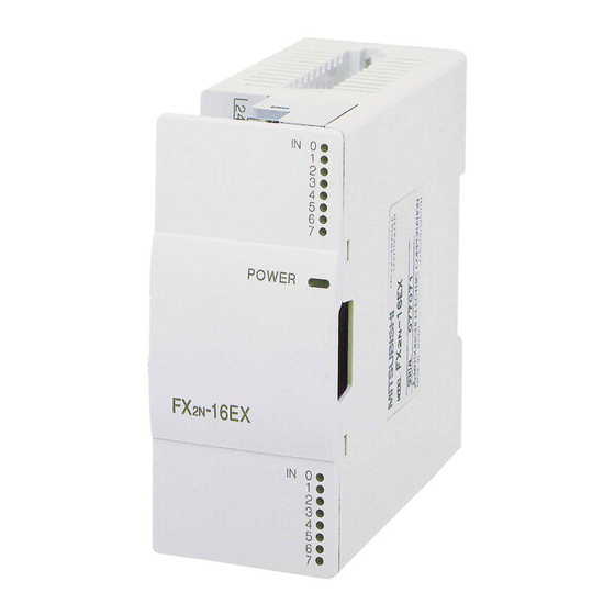
- Page 39 Series Programmable Contrller Installation Notes Product outline Description de l’appareil Gerätebeschreibung Descrizione dell’appare- cchio Descripción de las unidades Figure: 3.1 Features of the FX Description de l’API FX Beschreibung der FX -SPS Descrizione dell’FX Descripción de la FX IN 0 POWER 4 5 6 22 23 24 25 26...
- Page 40 Series Programmable Contrller Installation Notes Table: 3.1 Vista de conjunto Vue d’ensemble Übersicht der Feature table Componenti de los des composants Komponenten componentes Barra DIN Carril de montaje DIN rail 35mm (1.38 Rail DIN (35 mm) DIN-Schiene (35mm) (35mm)secondo DIN (35 mm) según inch) to DIN46277 selon DIN 46277 nach DIN 46277...
- Page 41 Series Programmable Contrller Installation Notes RUN/STOP Control RUN or STOP of the FX can be controlled by: The RUN/STOP switch mounted next to the programming port. A standard input (X0 to X17; X0 to X7 for FX -16M units) defined by the system parameters.
- Page 42 Series Programmable Contrller Installation Notes Commande Run/Stop de la FX La fonction RUN ou STOP de la FX2N peut être commandée: au commutateur RUN/STOP installé à côté du port de programmation; au moyen d’une entrée standard (X0 à X17; X0 à X7 pour des unités -16M ) définie par des paramètres système;...
- Page 43 Series Programmable Contrller Installation Notes Environmental specifications Conditions ambiantes Condizioni ambientali Umgebungsbedingungen Condiciones ambientales SPEC. 0 - 55 °C Operating Température de Temperatura di Temperatura de Betriebstemperatur 32 - 131 F temperature service esercizio servicio (-20) - 70 °C Storage Température de Temperatura di Temperatura de...
- Page 44 Series Programmable Contrller Installation Notes PC mounting arrangements To prevent a rise in temperature, mount the units to walls. Never mount them to the floor or ceiling of an enclosure. Figure 3.2 Single row arrangement Figure 3.3 Double row arrangement using extension cable FX -65EC (650mm (25.59 inch);...
- Page 45 Series Programmable Contrller Installation Notes Caution • Units should not be installed in areas subject to the following conditions: excessive or conductive dust, corrosive or flammable gas, moisture or rain, excessive heat, regular impact shocks or excessive vibration. • Take special care not to allow debris to fall inside the unit during installation e.g. cut wires, shavings etc.
- Page 46 Series Programmable Contrller Installation Notes DIN rail mounting Units can be ‘snap’ mounted on to 35mm (1.38 inch) DIN rail. To release the unit from a DIN rail mount; pull the spring loaded DIN clips away from the rail. Once the spring clips are clear, slide the unit up and off.
- Page 47 Series Programmable Contrller Installation Notes Direct mounting Montage direct Montaggio diretto Direkte Montage Montaje directo Table: 3.3 Hole positions Positions des trous Lochpositionen Posizioni dei fori Posiciones de los agujeros A = W-10 UNIT inches ± 0.2 ± 0.01 -16M 4.72 ë...
- Page 48 Series Programmable Contrller Installation Notes General notes Always ensure that mounted units and blocks are kept as far as possible from high-voltage cables, high-voltage equipment and power equipment. Instructions générales Assurez-vous que les appareils et modules soient montés le plus loin possible des lignes, installations et alimentations en tension à...
- Page 49 Series Programmable Contrller Installation Notes Extension Board Installation To install a special function extension board on the left side of the FX MPU: Remove the top cover of the FX Fit the board to the connector and position over the screw holes correctly. Using the M3 (0.12”) selftapping screws provided secure the board to the base unit.
- Page 50 Series Programmable Contrller Installation Notes Installation de la carte d’extension Pour installer une carte d’extension à fonctions spéciales du côté gauche de la MPU , il faut: retirer le couvercle supérieur de la FX placer la carte sur le connecteur et la positionner exactement au-dessus des trous des vis;...
- Page 51 Series Programmable Contrller Installation Notes 3 - 16...
- Page 52 Series Programmable Controllers Power Supply Introduction Introduction Einleitung Introduzione Introducción Terminal Occupation Klemmen- Assegnazione Ocupaciones Layouts des bornes belegungen dei morsetti de bornas Installation Installation Installation Installazione Instalación Notes Alimentation Spannungs- Alimentazione Alimentación Power supply en tension versorgung della tensione de tensión Inputs Entrées...
- Page 53 Series Programmable Controllers Power Supply 4 - 2...
- Page 54 Series Programmable Controllers Power Supply Wiring techniques The wiring of FX products has been designed to be safe and easy. If during the installation of these product or associated products concern is felt, please contact a professional electrician who is trained to the local and national standards applicable to the installation site.
- Page 55 Series Programmable Controllers Power Supply Wiring cautions • Do not run input signals in the same multicore cable as output signals or allow them to share the same wire. • Do not lay I/O signal cables next to power cables or allow them to share the same trunking duct.
- Page 56 Series Programmable Controllers Power Supply Termination at screw terminals Cables terminating at a screw terminal of an FX product should be fitted with insulated crimp terminals, see example shown. Terminals screws should be tightend to between 5 and 8 kg⋅cm (4.3 and 6.9 Inlbs). Screw terminals must be secured to prevent a loose connection from causing a malfunction.
- Page 57 Series Programmable Controllers Power Supply Power supply When wiring AC supplies the ‘Live’ cable should be connected to the ‘L’ terminal and the ‘Neutral’ cable should be connected to the ‘N’ terminal. When wiring DC supplies the ‘positive’ cable should be connected to the ‘+’ terminal and the negative cable should be connected to the ‘-’...
- Page 58 Series Programmable Controllers Power Supply Alimentation en tension Lors du raccordement d’une tension alternative (CA), le conducteur L doit être raccordé à la borne L et le conducteur N à la borne N. Lors du raccordement d’une tension continue (CC), le conducteur positif doit être raccordé à la borne (+) et le conducteur négatif à...
- Page 59 Series Programmable Controllers Power Supply Table: 4.1 Power requirements (all FX M/E type units) Alimentation en tension (tous les appareils FX M/E) Spannungsversorgung (alle FX M/E-Geräte) Alimentazione della tensione (tutti gli apparecchi FX M/E) Alimentación de tensión (todas las unidades FX M/E) M/E- ES/ESS/E M/E-DS/DSS...
- Page 60 Series Programmable Controllers Power Supply Table: 4.2 Power connection Raccordement Spannungs- Allacciamento Conexión de diagram de la tension anschluß della tensione tensión Class 3 ground Mise à la terre classe 3 Erdung Klasse 3 Messa a terra classe 3 Tierra clase 3 Alimentation en Spannungs- Alimentazione della...
- Page 61 Series Programmable Controllers Power Supply Earthing/Grounding Use a cable at least 2mm (AWG14) to ground equipment. Ground resistance must be less than 100Ω (class 3). Note that the ground cable must not be connected to the same ground as the power circuits. Grounding is recommended but if a proper ground cannot be provided the PC will still operate correctly without being grounded.
- Page 62 Series Programmable Controllers Power Supply Service power supply If the system being installed uses the service supply from both the PC and a powered extension block , then the 0V terminals should be linked. • DO NOT however, link the 24V terminals. •...
- Page 63 Series Programmable Controllers Power Supply Table: 4.3 Service Supply (all FX M/E-ES/ESS type units) Tension de service (tous les appareils FX M/E-ES/ESS) Service-Spannung (alle FX M/E-ES/ESSGeräte) Tensione di servizio (tutti gli apparecchi FX M/E-ES/ESS) Tensión de servicio (todas las unidades FX M/E-ES/ESS) FX: Without extension block -16M, FX...
- Page 64 Series Programmable Controllers Inputs Introduction Introduction Einleitung Introduzione Introducción Terminal Occupation Klemmen- Assegnazione Ocupaciones Layouts des bornes belegungen dei morsetti de bornas Installation Installation Installation Installazione Instalación Notes Alimentation Spannungs- Alimentazione Alimentación Power supply en tension versorgung della tensione de tensión Inputs Entrées Eingänge...
- Page 65 Series Programmable Controllers Inputs 5 - 2...
- Page 66 Series Programmable Controllers Inputs 24V DC input specifications Caractéristiques techniques des entrées pour 24 V CC Technische Daten der Eingänge Dati tecnici degli ingressi per 24 für DC 24 V V DC Datos técnicos de las entradas para 24 V CC Table: 5.1 Características input...
- Page 67 Series Programmable Controllers Inputs 5.1.1 Typical wiring Exemple de câblage Verdrahtungsbeispiel Ejemplo de cableado Esempio di cablaggio Figure: 5.1 Source (positive input connection, negative S/S) Source (émetteur) (pôle positif) Source (plusschaltend) Source (comando positivo) Source (conexión de positivo) Figure: 5.2 Sink (negative input connection, positive S/S) Sink (récepteur) (pôle négatif) Sink (minusschaltend)
- Page 68 Series Programmable Controllers Inputs Table: 5.2 Description du Positions- Descrizione della Descripción de Item check poste beschreibung posizione posición REF. Tension de service DC-Service- Tensione di servizio Tensión de servicio DC service supply Spannung Sensor de PNP (NPN) Capteur d’espace- PNP-/ NPN- Sensore di distanza aproximación...
- Page 69 Series Programmable Controllers Inputs External supply The example shown right, uses an external power supply to activate the inputs Alimentation externe 24V DC L’exemple de droite montre l’utilisation d’une tension de service externe pour activer les entrées. Source (-ve S/S) Externe Versorgung Das rechte Beispiel zeigt den Einsatz einer externen Versorgungsspannung zu...
- Page 70 Series Programmable Controllers Inputs 5.1.4 Resistors and inputs connected in parallel; Parallel resistance Rp: FX = 15kΩ. If resistance Rp is less than the stated value, then add Rb. See equation 1 for Rb calculation. Alternatively; Current leakage: FX = 1.5mA. If the current leakage is greater than the stated value, then add Rb.See equation 2 for Rb calculation.
- Page 71 Series Programmable Controllers Inputs Appareils de base avec entrées AC 110V Input, MPUs 110V CA Grundgeräte mit AC Apparecchi base con ingressi 110V-Eingängen 110V AC Unidades bas con Entradas de 110V CA Table: 5.3 -xxMR- Kenndaten der Características Caractéristiques Parametri degli UA1/UL -xxMR- de las entradas...
- Page 72 Series Programmable Controllers Inputs 5.2.1 110V AC input specifications Caractéristiques techniques des entrées pour 110 V CA Technische Daten der Eingänge für AC 110 V Dati tecnici degli ingressi per 110 V AC Datos técnicos de las entradas para 110 V CA Table: 5.4 -8EX-UA1/UL Caractéristiques...
- Page 73 Series Programmable Controllers Inputs 5.2.2 Typical wiring Exemple de câblage Verdrahtungsbeispiel Esempio di cablaggio Ejemplo de cableado Figure: 5.4 Typical wiring Exemple de câblage Verdrahtungsbeispiel Esempio di cablaggio Ejemplo de cableado Table: 5.5 Description du Positions- Descrizione della Descripción de Item check poste beschreibung...
- Page 74 Series Programmable Controllers Inputs 5.2.3 Programming caution When using 110V AC units, high speed counter and interrupt routines are not suitable for use due to the long ‘ON/OFF’ times. The following instructions are also not suitable. Instructions relatives à la programmation Lorsque vous utilisez un appareil pour 110 V CA, n’utilisez ni le High-Speed-Counter (compteur grande vitesse) ni les routines d’interruption pendant les périodes de MARCHE-ARRET prolongées pendant le service.
- Page 75 Series Programmable Controllers Inputs 5 - 12...
- Page 76 Series Programmable Controllers Outputs Introduction Introduction Einleitung Introduzione Introducción Terminal Occupation Klemmen- Assegnazione Ocupaciones Layouts des bornes belegungen dei morsetti de bornas Installation Installation Installation Installazione Instalación Notes Alimentation Spannungs- Alimentazione Alimentación Power supply en tension versorgung della tensione de tensión Inputs Entrées Eingänge...
- Page 77 Series Programmable Controllers Outputs 6 - 2...
- Page 78 Series Programmable Controllers Outputs Relay output specification Caractéristiques techniques des sorties des relais Technische Daten der Relais- Ausgänge Dati tecnici delle uscite a relè Datos técnicos de las salidas de relé Table: 6.1 relay Caractéristiques Kenndaten der Parametri dei Características de specification des relais FX Relais, FX...
- Page 79 Series Programmable Controllers Outputs 6.1.1 Reliability tests The test results in table 6.2 were gathered from a 1 sec ON/OFF test cycle. Please note that the over current induced by in-rush greatly reduces the relay contacts service life. The rated life for an inductive AC load such as a contactor or solenoid valve is 500,000 operations at 20VA.
- Page 80 Series Programmable Controllers Outputs 6.1.2 Relay output example Exemple d’un câblage de sortie de relais Beispiel einer Relais-Ausgangsbeschaltung Esempio del cablaggio di uscita di un relè Ejemplo de una conexión de salida de relé Figure: 6.1 Typical wiring Exemple de câblage Verdrahtungsbeispiel Esempio di cablaggio Ejemplo de cableado...
- Page 81 Series Programmable Controllers Outputs Triac (SSR) output specifications Caractéristiques techniques des sorties triac (SSR) Technische Daten der Triac(SSR)- Dati tecnici delle uscite triac(SSR) Ausgänge Datos técnicos de las salidas Triac(SSR) Table: 6.4 triac Caractéristiques Kenndaten der Parametri dei Características de specification des triac FX Triac, FX...
- Page 82 Series Programmable Controllers Outputs 6.2.1 In-rush currents These currents should be kept as low as possible. The root mean square (I < 0.2A. Reference Eqn 1 for (I - In-rush current (A) - In-rush time (sec) - Switch current (A) - Switch time (sec) - Operation time (sec) Impulsions de courant...
- Page 83 Series Programmable Controllers Outputs Exemple d’un câblage de sortie Triac output example triac Beispiel einer Triac-Aus- gangsbeschaltung Esempio del cablaggio di uscita di un triac Ejemplo de una conexión de salida Triac Figure: 6.3 Typical wiring Exemple de câblage Verdrahtungsbeispiel Esempio di cablaggio Ejemplo de cableado com1...
- Page 84 Series Programmable Controllers Outputs Transistor output specification Caractéristiques techniques des sorties des transistors Technische Daten der Transistor- Dati tecnici delle uscite a transis- Ausgänge Datos técnicos de las salidas transistorizadas Table: 6.6 Caractéristiques transistor Kenndaten der Parametri dei Características de des transistor specification Transistor FX...
- Page 85 Series Programmable Controllers Outputs 6.4.1 Response times OFF times increase as the load current decreases. For improved response times use a ‘dummy’ resistor, see Figure 6.4.If a response time of 0.5 msec or better is required when using ‘light loads’ use a ‘dummy’ resistor and ensure the signal line has a current greater than 60mA/24V DC.
- Page 86 Series Programmable Controllers Outputs Transistor output example Exemple d’un câblage de sortie de transistor Beispiel einer Transistor-Aus- Esempio del cablaggio di uscita gangsbeschaltung di un transistor Ejemplo de una conexión de salida transistorizada Figure: 6.5 MT-ESS, FX ET-ESS, (Source) MC2 MC1 Figure: 6.6 MT, FX ET (Sink)Japanese spec.
- Page 87 Series Programmable Controllers Outputs Applying safe loads Ensure all loads are applied to the same side of each PC output, see previous figures. Loads which should NEVER simultaneously operate (e.g. direction control of a motor), because of a safety critical situation, should not rely on the PC’s sequencing alone. Mechanical interlocks MUST be fitted to all safety critical circuits.
- Page 88 Series Programmable Controllers Diagnostics Introduction Introduction Einleitung Introduzione Introducción Terminal Occupation Klemmen- Assegnazione Ocupaciones Layouts des bornes belegungen dei morsetti de bornas Installation Installation Installation Installazione Instalación Notes Alimentation Spannungs- Alimentazione Alimentación Power supply en tension versorgung della tensione de tensión Inputs Entrées Eingänge...
- Page 89 Series Programmable Controllers Diagnostics 7 - 2...
- Page 90 Series Programmable Controllers Diagnostics Preliminary checks Vérifications à effectuer avant la mise en service Überprüfungen vor Betrieb Verificaciones preliminares Controlli prima del funzionamento Table: 7.1 Points de Punti da Puntos de Check list Prüfpunkte contrôle controllare verificación Check power A vérifier: Überprüfen: Controllare: Verificación:...
- Page 91 Series Programmable Controllers Diagnostics Diagnostic d’erreurs général Basic diagnostics Le diagnostic d’erreurs suivant vous The following diagnostic functions offre une aide pour la recherche et will help identify, common faults. l’élimination des perturbations. Allgemeine Fehlerdiagnose Diagnostica generale Die nachfolgende Fehlerdiagnose Le seguenti informazioni aiutano bietet Ihnen eine Hilfe zum Suchen nella ricerca e l’eliminazione delle...
- Page 92 Series Programmable Controllers Diagnostics Resultados Possible Résultats Mögliche Possibili risultati posibies de la results possibiles Prüfergebnisse dei controlli prueba de verificación POWER POWER BATT.V BATT.V PROG-E PROG-E CPU-E CPU-E Power LED remains OFF Power LED comes ON Possible fuse blown in the PC. Contact a Too many loads connected to the 24V DC Mitsubishi service center for repair work.
- Page 93 Series Programmable Controllers Diagnostics 7.2.2 BATT.V LED ON POWER LED BATT.V s’allume BATT.V-LED leuchtet BATT.V Il LED BATT.V si accende PROG-E CPU-E Diodo LED de BATT.V encendido Fault Perturbation Störung Anomalla Fallo / avería LED BATT.V BATT.V-LED Il LED BATT.V Diodo LED de BATT.V LED ON s’allume...
- Page 94 Series Programmable Controllers Diagnostics Resultados Possible Résultats Mögliche Possibili risultati posibies de la results possibiles Prüfergebnisse dei controlli prueba de verificación D8005 Monitor D8005. This Afficher les données Daten von D8005 Visualizzare i dati di Activar la indicación is the current battery de D8005.
- Page 95 Series Programmable Controllers Diagnostics 7.2.3 PROG.E LED flashes POWER LED PROG.E PROG.E-LED blinkt BATT.V LED PROG.E PROG-E CPU-E Diodo LED de PROG.E Fault Perturbation Störung Anomalla Fallo / avería PROG.E LED PROG.E-LED Diodo LED de LED PROG.E LED PROG.E flashes blinkt PROG.E Remedy...
- Page 96 Series Programmable Controllers Diagnostics 7.2.4 CPU.E LED ON POWER La LED CPU.E est allumée CPU.E-LED leuchtet BATT.V PROG-E Il LED CPU.E è acceso CPU-E Diodo LED de CPU.E encendido Fault Perturbation Störung Anomalla Fallo / avería La LED CPU.E CPU.E-LED Il LED CPU.E Diodo LED de CPU.E CPU.E LED ON...
- Page 97 Series Programmable Controllers Diagnostics Remedy Remède Abhilfe Rimedio Remedio Débrancher le Desembornar la Disconnect Erdungsanschluß Staccare il raccordement de conexión de puesta a earth/ground terminal abklemmen. collegamento a terra. terre. tierra. Resultados Possible Résultats Mögliche Possibili risultati posibies de la results possibiles Prüfergebnisse...
- Page 98 Series Programmable Controllers Diagnostics Remedy Remède Abhilfe Rimedio Remedio Possible program/scan Erreur éventuelle de Möglicherweise Probabile errore di Probablemente se time error. Check temps de cycle de Programmzykluszeit- tempo ciclo nel trata de un fallo de D8012 for program programme. Vérifier Fehler.
- Page 99 Series Programmable Controllers Diagnostics Common errors Corroded contact points at some point in an I/O line. An I/O device has been used outside its specified operating range. An input signal occurs in a shorter time period than that taken by one program scan. 24V DC power supply is overloaded.
- Page 100 Series Programmable Controllers Diagnostics Replacing the battery Turn OFF PC’s power supply. Remove top cover (Z) from the PC. Remove battery from holder - disconnect and replace (this should be carried out in 20 sec if the current data held in the PC’s RAM is not to be lost. Refit battery and cover.
- Page 101 Series Programmable Controllers Diagnostics Maintenance Battery has a 5 year life (3 years when used with FX-RAM-8). Check interior temperature of the panel. Check panel air filters if fitted. Check for loosening of terminals or mounting facilities (due to vibration). Entretien Durée de vie de la batterie: 5 ans (3 ans en cas d’utilisation de la FX-RAM-8).
- Page 102 Series Programmable Controllers Diagnostics Error flags ON indicates error. Indicateurs d’erreurs “MARCHE” désigne une erreur. Fehlermerker EIN bezeichnet Merker di errore ON indica un er- einen Fehler. rore. Marcadores de fallos/errores “CONEXION” designa un fallo o error. Table: 7.2 M8004 - M8039 Indicateurs Marcadores de Error flags...
- Page 103 Series Programmable Controllers Diagnostics Table: 7.3 M8060 - M8069 Indicateurs Marcadores de Error flags Fehlermerker Merker di errore d’erreurs fallos/errores M8060 I/O configuration Affectation E/S E-/A- Zuweisung Assegnazione I/O Asignación E/S (ref. error défectueuse fehlerhaft errata errónea D8060) M8061 Défaut matériel de SPS-Hardware- Errore hardware Fallo en el...
- Page 104 Series Programmable Controllers Diagnostics Error registers Registre d’erreurs Registri di errore Fehlerregister Registro de fallos/errores Table: 7.4 D8000 - D8009 Registre Registro de Error registers Fehlerregister Registri di errore d’erreurs fallos/errores D8000 Watchdog timer WatchDogTimer (default Watchdog timer (surveillance du Watch-Dog-Timer Timer watch dog (timer de vigilancia)
- Page 105 Series Programmable Controllers Diagnostics Table: 7.5 D8060 - D8069 Registre Registro de Error registers Fehlerregister Registri di errore d’erreurs fallos/errores Reports location of L’affectation E-/A-Adressenzu- Asignación de Assegnazione I/O configuration d’adresses E/S est weisung ist dirección E/S D8060 errata di indirizzi error défectueuse fehlerhaft...
- Page 106 Series Programmable Controllers Diagnostics Error codes Codes d’erreurs Codici di errore Fehlercodes Códigos de fallo/error Table: 7.6 D8061 - D8062 Códigos de Error codes Codes d’erreurs Fehlercodes Codici di errore fallo/error Controllare i Comprobar las Check cable Vérifier les liaisons Kabelverbindungen D8061 collegamenti dei...
- Page 107 Series Programmable Controllers Diagnostics Table: 7.7 D8063 Códigos de Error codes Codes d’erreurs Fehlercodes Codici di errore fallo/error Vérifier Spannungsversor- Controllare la Verificar la Check both power l’alimentation en gung und tensione di alimentación de D8063 tension et les Kommunikations- alimentazione e i tensión y las communications...
- Page 108 Series Programmable Controllers Diagnostics Vue d’ensemble des instructions Instruction list relatives aux applications Übersicht der Applikatios-an- Elenco delle istruzioni applicative weisungen Vista de conjunto de las ins-truc- ciones de aplicación Table: 7.8 Numerically sorted Classement numérique Numerisch sortiert In ordine numerico Clasificación numérica 000 PROGRAM FLOW CALL...
- Page 109 Series Programmable Controllers Diagnostics Table: 7.9 Alphabetically sorted Classement alphabétique Alphabetisch sortiert In ordine alfabetico Clasificación alfabética Symbol FNC No. Symbol FNC No. D Symbol FNC No. ABSD GBIN SEGD SEGL 232-238 SFRD HSCR SFTL HSCS SFTR ARWS SFWR ASCI INCD SMOV SORT...
- Page 110 Series Programmable Controllers Diagnostics 8000 steps, FX-RAM-8 = 8k - 16k steps X000 FX-EPROM-8 = 8k - 16k steps Y010 T020 FX-EEPROM-16 = 4k - 16k steps K010 X0 - 377 (256 pnts) (X+Y) ≤ 256 pnts Max. Y0 - 377 (256 pnts) M0-M499 (500 pnts) M500 - M1023 (524 pnts)
- Page 111 Series Programmable Controllers Diagnostics 7 - 24...
- Page 112 Programmable Controllers Index Introduction Introduction Einleitung Introduzione Introducción Terminal Occupation Klemmen- Assegnazione Ocupaciones Layouts des bornes belegungen dei morsetti de bornas Installation Installation Installation Installazione Instalación Notes Alimentation Spannungs- Alimentazione Alimentación Power supply en tension versorgung della tensione de tensión Inputs Entrées Eingänge...
- Page 113 Programmable Controllers Index 8 - 2...
- Page 114 Programmable Controllers Index Maintenance General maintenance ..7-14 AC powered base units Replacing the battery ..7-13 FX2N units ....1-4 Model name Approvals .
- Page 115 Programmable Controllers Index Wiring Advice ....4-3 Caution ....4-4 Connecting 110V AC inputs .
- Page 116 Programmable Controllers Index Entrées: caractéristiques techniques Câblage des entrées 110V CA ..5-10 Accessoires des appareils ..1-7 Câblage des entrées (Sink) ..5-4 Alimentation en tension Câblage des entrées (Source) .
- Page 117 Programmable Controllers Index Sécurité Symboles utilisés dans le manuel . . . iii Prescriptions de sécurité ..iii Sorties: caractéristiques techniques Câblage de sortie de relais ..6-5 Câblage de sortie de transistor .
- Page 118 Programmable Controllers Index Gerätezubehör ....1-7 Grundgeräte AC-Grundgerät AC-Spannung FX2N-Geräte ....1-4 (Relais-/Transistor-Ausgänge) . . . 1-4 Allgemeine Merkmale DC-Grundgeräte FX2N-Geräte .
- Page 119 Programmable Controllers Index Seriennummer Erläuterung ....1-9 Service-Spannung Servicespannung von DC 24 V ..4-11 Systemausrüstung ... 4-8 Systemisolierung .
- Page 120 Programmable Controllers Index Dati caratteristici dei cavi Cavi di messa a terra ..4-12 Accessori ....1-9 Cavi di potenza .
- Page 121 Programmable Controllers Index Sicurezza Direttive di sicurezza ..v Simboli usati nel manuale ..v Sostituzione della batteria ..7-13 Tempo di risposta quando si usa un transistor .
- Page 122 Programmable Controllers Index Entradas: Datos técnicos Cableado de las entradas 110V CA . . . 5-10 Accesorios de las unidades ..1-7 Cableado de las entradas Alimentación de tensión (de conexión Sink) ..5-4 Aislamiento del sistema .
- Page 123 Programmable Controllers Index Registro de fallos/errores ..7-17 Relé Fiabilidad ....6-4 Salidas ....6-3 Resistencia en paralelo con las entradas Salidas: Datos técnicos Conexión de salida de relé...