CAME V6000 Installation Manual
Hide thumbs
Also See for V6000:
- Installation manual (33 pages) ,
- Installation & operation manual (21 pages) ,
- Installation manual (17 pages)
Advertisement
Quick Links
Advertisement

Related Manuals for CAME V6000


Summary of Contents for CAME V6000
- Page 1 OPERATORS FOR GARAGE DOORS FA00047-E N INSTALLATION MANUAL V6000 English...
- Page 2 HIS PRODUCT SHOULD ONLY BE USED FOR THE UITABLY SECTION OFF AND DEMARCATE THE PURPOSE FOR WHICH IT WAS EXPLICITLY DESIGNED ENTIRE INSTALLATION SITE TO PREVENT UNAUTHORIZED . CAME S. NY OTHER USE IS DANGEROUS PERSONS FROM ENTERING THE AREA ESPECIALLY •...
- Page 3 EEP ANY REMOTE CONTROL TRANSMITTERS OR ANY URTHER RECOMMENDATIONS FOR ALL • K OTHER COMMAND DEVICE AWAY FROM CHILDREN EEP CLEAR OF HINGES AND MECHANICAL MOVING • D PREVENT THE OPERATOR FROM BEING ACCIDENTALLY PARTS O NOT ENTER THE OPERATOR S AREA OF .
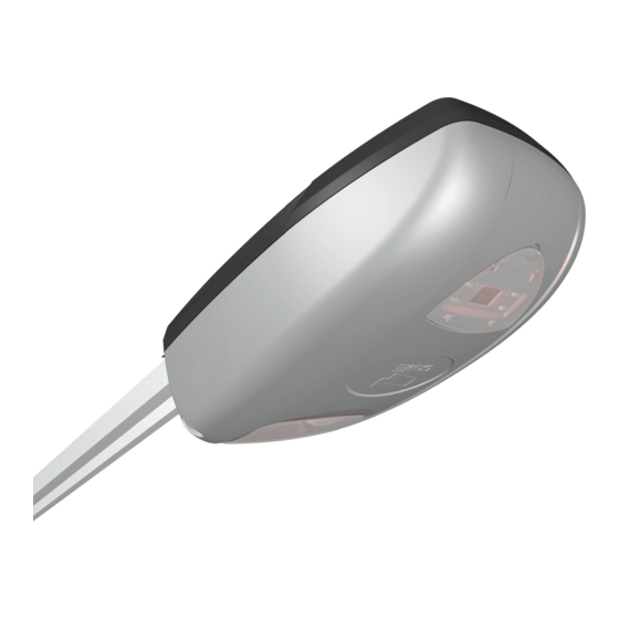
- Page 4 ABS casing with display for keypad programming and an LED courtesy light. Intended use The V6000 operator is designed to power overhead and sectional garage door used in homes and apartment buildings. Any installation and/or use other than that specified in this manual is forbidden.
- Page 5 Packing list 1. one Operator 2. one Installation Manual 3. two anchoring perforated-plates. 4. one Curved lever 5. Two support braces 6. Three U-shaped braces 7. One guide-fitting brace 8. One door fitting brace 9. Eight self-drilling hexagonal head M6x15 screws 10.
- Page 6 001V06003 Chain guide T = 4.02 m. - Spring-balanced overhead doors up to 3.25 m in height. - Sectional* doors up to 3.20 m in height. 001V06005 Belt guide T = 3.02 m. Counter-balanced overhead doors up to 2.4 m in height - Counter-balanced overhead doors up to 2.25 m in height - Sectional* doors up to 2.20 m in height.
- Page 7 Cable types and minimum thicknesses Cable length Cable length Connection Cable type 1 < 15 m 15 < 30 m Control panel power supply 230 V AC H05VV-F 3G x 1.5 mm 3G x 2.5 mm Flashing light 2 x 0.5 mm FROR CEI Photocell transmitters 2 x 0.5 mm...
- Page 8 Applicative examples SECTIONAL DOOR * double-guide sectional * single-guide sectional door door COUNTERBALANCED OVERHEAD DOOR, SPRING-BALANCED OVERHEAD DOOR, fully retracting and protruding partially retracting and protruding INSTALLATION The following illustrations are just examples, in that the space available for fitting the operator and accessories varies depending on the overall dimensions.
- Page 9 Fastening the traction guide D Fasten the traction guide to the center of the doorway, using suitable screws. E Raise the guide and position in horizontally to measure the distance to the ceiling, then fasten it. F Instal the support braces and the U-shaped brace b onto the guide.
- Page 10 Fitting the operator to the guide Fit the adapter to the drive shaft. The operator can be fi tted onto the guide: either in standard position or at a right angle Self-drilling 6 x 15 screw U-shaped brace Micro Guide Drive shaft with adapter Self-drilling 6 x 15 screw Guide...
- Page 11 Moving the micro switch Disconnect the cables of the micro switch and remove the latter. N Remove the operator's cover and the gable brace. Pull out the electrical cable and fi t it through the hole. Refi t the cable brace so as to block the hole. Use a screwdriver to open up the predrilled hole for the electrical cables of the micro switch and fi...
- Page 12 Release the operator Release ⓒ To release the operator, pull down on the ⓒ cord. Locking To lock the operator back up, use the transmitter or the control button. ELECTRICAL CONNECTIONS Before powering up the board, cut off the mains FUSE TABLE power supply.
- Page 13 Movement control and obstacle detection When OPENING:the door stops. To resume movement, either press a button or use the transmitter. When CLOSING: inverts the direction of travel until opening is complete. After three consecutive inversions, the door stays open and excludes the automatic closing: to close, either use the transmitter or button.
- Page 14 (NC) contact for reopening during closing. Input for safety devices such as photocells, sensitive safety-e- dges and other devices that are compliant with EN 12978 standards. During closing, opening this contact triggers an inversion of movement until the door is completely open. If a device is connected, remove the bridge Signaling devices Flashing light (contact rated for: 24 V - 25 W max).
- Page 15 Obligatory functions Establishing the opening limit-switch points Respect the order of settings of the limit switches shown in this manual. With the operator idle Press P for about fi ve Press +. seconds. ” The operator emits a sound Let the door reach the signal and 1 appears.
- Page 16 Memorizing the programming It is OBLIGATORY to conclude the programming procedures with this function so as not to lose any saved settings! Press + to select 5. Press P. The display segments rotate clockwise. The programming has been memorized. Adjusting the sensitivity The door must be properly balanced.
- Page 17 Optional functions Setting the alarm By default, this function is deactivated; by activating the alarm function, the operator emits a long sound signal if the door stays open for more than 10 minutes. To activate it: Press P for about fi ve Press + and select 1.
- Page 18 The operator emits a sound signal for 20 seconds before the door starts to automatically close. Simultaneou- sly, the courtesy light fl ashes. When the door starts closing, the operator emits a sound signal and the courtesy light is on. When the door is closed, the operator does not emit any sound signal and the courtesy light stays on for three minutes.
- Page 19 Memorizing the transmitters You can memorize up to 16* diff erent codes/users. When the operator is idle: Press and keep pressed S until 0 appears on the left side of the screen. The segments of the 0 on the left side of the screen rotate clockwise.
- Page 20 TROUBLESHOOTING ISSUES CHECKS AND FIXES • The operator neither opens nor closes • Check the power supply and line fuses • The (1-2) NC safety contact is open • The operator opens but does not close • The N.C. safety contact (2-C1) is open •...
- Page 21 MAINTENANCE Periodic maintenance ☞ Before doing any maintenance, cut off the mains power supply, to prevent any hazardous situations resulting from the door's unexpected movement. Periodic maintenance log kept by users (every six months) Date Notes Signature...
- Page 22 Extraordinary maintenance The following table is for logging any extraordinary maintenance jobs, repairs and improvements performed by specialized contractors. Any extraordinary maintenance jobs must be done only by specialized technicians. Extraordinary maintenance log Fitter's stamp Name of operator Job performed on (date) Technician's signature Requester's signature Job performed ________________________________________________________...
- Page 23 ☞ CAME S.p.A. applies a certified Environmental Management System at its premises, which is compliant with the UNI EN ISO 14001 standard to ensure the environment is safeguarded. Please continue safeguarding the environment. At CAME we consider it one of the fundamentals of our operating and market strategies. Simply follow these brief disposal guidelines:...
- Page 24 Came S.p.A. Came S.p.A. Via Martiri Della Libertà, 15 Via Cornia, 1/b - 1/c 31030 Dosson di Casier Dosson di Casier 33079 Sesto al Reghena Sesto al Reghena Treviso Treviso - Italy Pordenone Pordenone - Italy (+39) 0422 4940 (+39) 0434 698111...
Need help?
Do you have a question about the V6000 and is the answer not in the manual?
Questions and answers