CAME V6000 Installation Manual
For garage doors
Hide thumbs
Also See for V6000:
- Installation manual (33 pages) ,
- Installation & operation manual (21 pages) ,
- Installation manual (24 pages)
Table of Contents
Advertisement
Quick Links
Advertisement
Table of Contents

Related Manuals for CAME V6000


Summary of Contents for CAME V6000
- Page 1 OPERATOR 119EV88EN FOR GARAGE DOORS INSTALLATION MANUAL V6000 English...
- Page 2 • This product should only be used for the purpose for which it was explicitly de- to perform OPERATIONS THEY ARE NOT EXPLICITLY REQUIRED AND ASKED to do in signed. Any other use is considered dangerous. CAME Cancelli Automatici S.p.A. the manuals. For repairs, adjustments and extraordinary maintenance, CONTACT is not liable for any damage resulting from improper, wrongful or unreasonable THE SPECIALIST TECHNICAL SERVICE CENTRE •...
- Page 3 ☞ This symbol tells you what to say to the end users. REGULATORY REFERENCES Came Cancelli Automatici is a company with an ISO 9001-certified company quality management system and an ISO 14001-certified environmental management system. The product in question complies with the regulations referred to in the declaration of conformity.
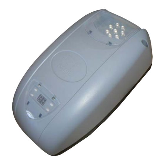
- Page 4 Description of the components Operator Cover Gearmotor Transformer Control board Power cord Packing list of pre-assembled rail 6. Rail 7. Chain or belt 8. Block 9. In-line transmission arm 10. Release cord Slide rail 001V06001 Chain rail L = 3,02 m. - Canopy overhead doors up to 2.40 m in height;...
-
Page 5: General Installation Instructions
GENERAL INSTALLATION INSTRUCTIONS Installation must be carried out by qualified and experienced personnel in compliance with applicable regulations. Preliminary checks Before starting installation: • Provide a suitable single-pole disconnection device, with a maximum of 3 mm between the contacts, to disconnect the power supply; •... -
Page 6: Examples Of Use
Examples of use SECTIONAL DOOR * sectional door * sectional door with double rail with single rail CANOPY OVERHEAD DOORS, with partially retracting movement. SPRING-BALANCED OVERHEAD DOOR,, with fully retracting movement INSTALLATION The following illustrations are only examples, given that the space for securing the gearmotor and accessories varies in relation to dimensions. The installation technician is responsible for choosing the most suitable solution. - Page 7 Install the support brackets and the U-bracket on the rail. Adapt the pierced plates, bending them, in order to compensate for the distance of the rail from the ceiling. Secure the plates to the support brackets and the U-bracket using the screws and nuts supplied. Drill the ceiling at the point of the plate fi xing holes. Secure the plates to the ceiling using suitable screws and anchors.
-
Page 8: Electrical Connections
Remove the cover of the operator and the cable clamp. Slide out the electrical cable and route into the through-hole. Refi t the cable clamp so that the hole is blocked. Use the screwdriver to pierce the preformed hole to pass the microswitch electrical cables through and fi t the cables into the micro. Secure the micro to the operator. Connect the connectors in the respective positions on the microswitch. -
Page 9: Description Of The Components
Description of the components Line fuse Gearmotor Transformer Cable inlet AF board connector Cable-antenna Photocell connection terminal block STOP button connection terminal block Limit switch connection terminal block Encoder connection terminal block Display connection terminal block Motor connections Transformer connection Courtesy light connection terminal block Antenna connection terminal block Flashing light connection terminal block... - Page 10 Power supply The operator is supplied with an electric cable (L = 1.2 m) with Shuko socket already connected. Warning devices Flashing light (contact capacity: 24 V - 25 W max). It fl ashes during opening and closing. Control devices If a device is connected, remove the jumper OPEN-STOP-CLOSE-STOP function from the control device (N.O.
-
Page 11: Adjusting Sensitivity
Some functions must be set so that the operator is able to work properly while others are optional Mandatory functions Determining the end-run points when opening Follow the end-run point setting order indicated in this manual. While operator is not moving Determining the end run points while closing Checking run self-learning Press P for about 5... -
Page 12: Optional Functions
Optional functions Setting the alarm Adjusting the automatic closing intervention time; By default, the function is deactivated; when the By default, the function is disabled. To activate it: alarm is active the operator will emit a beep if the door remains open for more than 10 minutes. To activate it: Press P for about 5 sec- onds, 1 appears. - Page 13 Activating the radio control Additional outdoor antenna Disconnect the indoor antenna and connect the outdoor antenna to the appropriate terminals on the board. Radio frequency card For proper operation, before inserting the AF plug-in card, INTERRUPT LINE VOLTAGE. Saving the transmitters Deleting the transmitters You can store up to a maximum of 16* diff erent codes/users With the operator at a standstill:...
-
Page 14: Periodic Maintenance
MAINTENANCE ☞ Before any maintenance, disconnect power to prevent any possible dangerous situations that can be caused by accidental movement of the operator. Lubricate the rotation points with grease whenever abnormal vibrations or squeaking occurs. Periodic maintenance Periodic maintenance log to be completed by the user (every six months) Date Notes Signature... -
Page 15: Troubleshooting
☞ CAME CANCELLI AUTOMATICI S.p.A. implements an EN ISO 14001-certified and compliant Environmental Management System at its plants, to ensure environmental protection. Please continue our efforts to protect the environment, something that CAME considers to be one of the foundations in developing its business and market... - Page 16 HR • Za sve dodatne informacije o poduzeću, proizvodima i tehničkoj podršci: UK • Для отримання будь-якої іншої інформації про компанію, продукцію та технічну підтримку: www. came.com www. came.com CAME Cancelli Automatici S.p.a. CAME Cancelli Automatici S.p.a. Via Martiri Della Libertà, 15 31030 Dosson Di Casier...
Need help?
Do you have a question about the V6000 and is the answer not in the manual?
Questions and answers