Toro Workman 07390 Operator's Manual
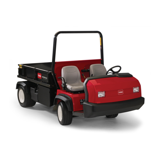
Workman hdx-auto utility vehicle
Hide thumbs
Also See for Workman 07390:
- Operator's manual (72 pages) ,
- Service manual (280 pages) ,
- Operator's manual (68 pages)
Table of Contents
Advertisement
Advertisement
Table of Contents

Related Manuals for Toro Workman 07390


Summary of Contents for Toro Workman 07390
- Page 1 Form No. 3406-489 Rev C Workman ® HDX-Auto Utility Vehicle Model No. 07390—Serial No. 316000001 and Up Model No. 07390H—Serial No. 316000001 and Up Model No. 07390TC—Serial No. 316000001 and Up *3406-489* C Register at www.Toro.com. Original Instructions (EN)
- Page 2 Whenever you need service, genuine Toro parts, or additional information, contact an Authorized Service Dealer or Toro Customer Service and have the model and serial numbers of your product ready. Figure 1 identifies the location of the model and serial numbers on the product.
- Page 3 Contents Using the Bed Support........40 Removing the Full Bed........41 Installing the Full Bed........41 Safety ............... 4 Raising the Machine ......... 42 Safe Operating Practices........4 Removing and Installing the Hood ....43 Supervisor’s Responsibilities......4 Lubrication ............44 Before Operating ..........
-
Page 4: Safety
Before Operating Safety • This machine is designed to carry the operator Improper use or maintenance by the operator or and 1 passenger in the seat provided by the owner can result in injury. To reduce the potential manufacturer. Do not carry any other passengers for injury, comply with these safety instructions on the machine. -
Page 5: General Operation
• Do not remove the fuel cap or add fuel with the and down slopes. Reduce the speed of the engine running. machine when making sharp turns or when turning on hillsides. Avoid turning on hillsides • Allow the engine to cool before refueling. whenever possible. -
Page 6: Braking
Operating on Hills Repair all damage to the machine before you start operation again. • Lightning can cause severe injury or death. If you WARNING see lightning, do not operate the machine; seek shelter. Operating the machine on a hill may cause tipping or rolling of the machine, or the engine may stall and you could lose headway on the Braking... -
Page 7: Operating On Rough Terrain
Operating on Rough Terrain • The rear cargo space is intended for load carrying purposes only, not for passengers. Reduce the ground speed of the machine and the • Do not overload your machine. The name plate load carried in the machine when operating on rough (located under the middle of the dash) shows terrain, uneven ground, and near curbs, holes, and the load limits for the machine. -
Page 8: Rollover Protection System (Rops Safety
The maximum engine speed can release it quickly in an emergency. is 3,650 rpm. To ensure safety and accuracy, have an Authorized Toro Distributor to check the • Check carefully for overhead obstructions and do maximum engine speed with a tachometer. - Page 9 decal93-9868 93–9868 1. Crushing hazard of hand—read the Operator’s Manual. decal93-9879 93-9879 1. Stored energy hazard—read the Operator's Manual. decal105-7977 105–7977 1. Tank 2. Pressure decal93-9899 93-9899 1. Crushing hazard—install the cylinder lock. decal106-2353 106-2353 decal105-4215 105-4215 1. Electrical power point 1.
- Page 10 decal106-7767 106-7767 1. Warning—read the Operator's Manual; avoid tipping the machine; wear the seat belt; lean away from the direction the machine is tipping. decal115-2047 115-2047 1. Warning—do not touch the hot surface. decal115-2282 115-2282 1. Warning—read the Operator's Manual. 2.
- Page 11 decal115-7739 115-7739 1. Falling, crushing hazard, bystanders—no riders on machine decal115-7756 115-7756 1. High-flow hydraulics—engaged decal115-7723 115-7723 1. Warning—the hydraulic-fluid pressure is 124 bar (1,800 psi). 2. Coupler A 3. Coupler B decal121-9776 121-9776 1. Warning—read the Operator’s Manual and receive proper 4.
- Page 12 decal121-9890 121-9890 1. Parking brake 7. Fast 4. Cylinder retract 2. Hydraulic system—unlock 5. Cylinder extend 8. Slow 3. Hydraulic system—lock 6. Transport decal127-8620 127-8620 1. Head lights 4. Horn 7. Engine—start 2. Differential lock—lock 5. Engine—shut off 8. Brake 3.
- Page 13 decal127-8626a decal127-8760 127-8626 127–8760 1. Power takeoff (15 A) 5. Differential lock (15 A) 1. Park 4. Low gear 2. Start engine (10 A) 6. Speedometer (10 A) 2. Reverse 5. Drive 3. Hazard lights (10 A) 7. Headlights and rear lights 3.
-
Page 14: Setup
Setup Loose Parts Use the chart below to verify that all parts have been shipped. Procedure Description Qty. Steering wheel Install the steering wheel (TC and H Cover models only). Washer (5/8 inch) Connect the battery (TC and H models –... -
Page 15: Installing The Steering Wheel
Installing the Steering Connecting the Battery Wheel TC and H Models Only TC and H Models Only No Parts Required Parts needed for this procedure: Procedure Steering wheel Cover WARNING Washer (5/8 inch) Incorrectly routing the battery cable could damage the machine and cables, causing sparks. -
Page 16: Checking The Fluid Levels And Tire Pressure
4. Check the brake-fluid level before you first start the engine; refer to Checking the Brake-Fluid Level (page 28). 5. Check the air pressure in the tires; refer to Checking the Tire Pressure (page 31). Installing the Rollover Protection System (ROPS) g026250 Figure 5 Parts needed for this procedure:... -
Page 17: Connecting The Cvt-Intake Duct
4. Remove the bed support, lower the bed, shut off the engine, and remove the key. Connecting the CVT-Intake Duct Burnishing the Brakes No Parts Required No Parts Required Procedure Procedure Important: Remove the plastic bag covering the end of the CVT duct before starting the engine. To ensure optimum performance of the brake system, The CVT Kit (Part No. -
Page 18: Product Overview
Transmission Lever Product Overview Use the transmission lever (Figure 9) to shift the transmission between P ( ), R ( ), N Controls PARK REVERSE ), L ( ), and D ( ) ground NEUTRAL LOW FORWARD DRIVE operation. Note: Determine the left and right sides of the machine from the normal operating position. - Page 19 Parking-Brake Lever Whenever you shut off the engine, engage the parking brake (Figure 10) to prevent the machine from accidentally moving. If the machine is parked on a steep grade, ensure that you engage the parking brake. • To engage the parking brake, pull back on the parking-brake lever.
-
Page 20: Control Panel
Control Panel Key Switch Use the key switch (Figure 13) to start and shut off the engine. To shut off the engine, rotate the key switch counterclockwise to the O position. The key switch has 3 positions: O , and . - Page 21 If the oil level is low, but adding oil does not cause the light to go out when the engine is started, shut off the engine immediately, and contact your Authorized Toro Service Dealer for assistance. Check the operation of the warning lights as follows: 1.
-
Page 22: Passenger Handhold
Passenger Handhold The passenger handhold is located on the dashboard (Figure 16). g009815 Figure 16 1. Passenger handhold 2. Storage compartment Seat-Adjustment Lever You can adjust the seat forward and rearward for your comfort (Figure 17). g021227 Figure 17 1. Seat-adjustment lever... -
Page 23: Specifications
191 cm (75 inches) to the top of the roll bar Attachments/Accessories A selection of Toro approved attachments and accessories is available for use with the machine to enhance and expand its capabilities. Contact your Authorized Service Dealer or Distributor or go to www.Toro.com for a... -
Page 24: Operation
Operation Note: Determine the left and right sides of the machine from the normal operating position. CAUTION A raised bed full of material without the proper safety support may lower unexpectedly. Working under an unsupported raised bed may cause injury to you or others. •... -
Page 25: Checking The Fluid Levels
Checking the Engine-Oil Level Service Interval: Before each use or daily—Check the engine-oil level. (Check the oil level before and after the engine is first started and daily thereafter.) Oil Type: 10W-30 API SJ or higher. Refer to the table in Figure 20 for oil viscosity according to ambient-air temperature. - Page 26 3. Remove dipstick and check the level of the oil Hydraulic-Fluid Capacity: (Non-TC model with the (Figure 21). High-Flow-Hydraulic Kit (option) or TC Model): 15.1 L (4 US gallons) 4. If the oil level is low, remove the filler cap (Figure 21) and add enough oil to raise the level to the WARNING...
- Page 27 Checking the Engine-Coolant Level Service Interval: Before each use or daily Check the Coolant level at the overflow reservoir only. Do not remove the radiator cap. (Check the coolant level before the engine is first started and daily thereafter.) Coolant type: a 50/50 solution of water and permanent ethylene-glycol antifreeze 1.
- Page 28 g009817 Figure 26 1. Brake-fluid reservoir G019522 g019522 Figure 25 1. Coolant-reserve tank 3. If coolant is low, remove the reserve tank cap and add a 50/50 mixture of water and permanent ethylene-glycol antifreeze. Note: Do not overfill. 4. Install the reserve-tank cap. Checking the Brake-Fluid Level g002379 Figure 27...
-
Page 29: Checking The Oil-Pressure-Warning Light
Checking the DANGER Oil-Pressure-Warning In certain conditions, fuel is extremely flammable and highly explosive. A fire or Light explosion from fuel can burn you and others and can damage property. Service Interval: Before each use or daily • Fill the fuel tank outdoors, in an open area, Note: If you just shut off the engine, it may take 1 to when the engine is cold. - Page 30 DANGER In certain conditions during fueling, static electricity can be released causing a spark which can ignite the fuel vapors. A fire or explosion from fuel can burn you and others and can damage property. • Always place fuel containers on the ground away from your machine before filling.
-
Page 31: Checking The Tire Pressure
Checking the Tire Pressure Removing Debris from the Cooling System Service Interval: Before each use or daily The air pressure in the front tires should be 220 kPa Service Interval: Before each use or daily (Clean it (32 psi) and the rear tires should be 124 kPa (18 psi). more frequently in dirty conditions.) Important: 1. -
Page 32: Performing Pre-Start Checks
1. Press the brake pedal. • Check all fluid levels and add the appropriate amount of Toro-specified fluids, if any are found 2. Disengage the parking brake. to be low. 3. Move the transmission lever to the desired gear. -
Page 33: Using The Speed-Range Control
Using the Speed-Range Using the Differential Lock Control WARNING Use the lever of the speed-range control to limit the Tipping or rolling the machine on a hill can maximum ground speed of the machine for operations cause a serious injury. that require a constant speed like spraying and top dressing. -
Page 34: Breaking In A New Machine
Checking the Safety-Interlock System Service Interval: Before each use or daily The purpose of the safety-interlock system is to prevent the engine from cranking or starting unless the brake pedal is pressed and the hydraulic-lift lever is in the N position. -
Page 35: Transporting The Machine
3. Set the high-flow-hydraulic switch to the O In case of an emergency, the machine can be position. towed for a short distance. However, Toro does not recommend this as a standard procedure. 4. Press brake pedal. 5. Rotate the key switch clockwise to the S... -
Page 36: Using The Hydraulic Control
can cause poor performance or damage to the brakes, axle, engine, transaxle, steering, suspension, body structure, or tires. Important: To reduce potential for drive line damage, use low range. When towing fifth-wheel attachments, like a fairway aerator, always install the wheel bar (included with the fifth wheel kit) to prevent the front wheels from lifting off the ground if the towed attachments movement is suddenly impaired. - Page 37 the system, then check hydraulic-fluid level – The quick couplers are interchanged. again. The attachment cylinder slightly affects • There is a squealing noise. the fluid level in the transaxle. Operating the – Remove the valve left in the O detent position machine with a low hydraulic-fluid level can damage the pump, remote hydraulics, power...
-
Page 38: Maintenance
Note: Download a free copy of an Electrical Schematic or Hydraulic Schematic schematic by visiting www.Toro.com and searching for your machine from the Manuals link on the home page. CAUTION Only qualified and authorized personnel should maintain, repair, adjust, or inspect the machine. -
Page 39: Operating In Adverse Conditions
Maintenance Service Maintenance Procedure Interval • Check the battery-fluid level (every 30 days if in storage). Every 50 hours • Check the battery-cable connections. • Grease all bearings and bushings (lubricate more frequently in heavy duty applications). • Change the air-cleaner filter (more frequently in dusty or dirty conditions). Every 100 hours •... -
Page 40: Pre-Maintenance Procedures
Pre-Maintenance Procedures Many of the subjects covered in this maintenance section require raising and lowering the bed. To prevent serious injury or death, take the following precautions. WARNING A raised bed full of material without the proper safety support may lower unexpectedly. Working under an unsupported raised bed may cause injury to you or others. -
Page 41: Removing The Full Bed
Removing the Full Bed Installing the Full Bed 1. Start the engine, engage the hydraulic-lift lever, Note: If you are installing the bed sides on the flat and lower the bed until the cylinders are loose bed, it is easier to install them before installing the in the slots. -
Page 42: Raising The Machine
Raising the Machine DANGER A machine on a jack may be unstable and slip off the jack, injuring anyone beneath it. • Do not start the machine while the machine is on a jack. • Always remove the key from the key switch before getting off the machine. -
Page 43: Removing And Installing The Hood
3. Pivot the top of hood forward and unplug the wire connectors from the headlights (Figure 45). 4. Remove the hood. Installing the Hood 1. Connect the lights. 2. Insert the top mounting tabs into the frame slots (Figure 45). 3. -
Page 44: Lubrication
Lubrication Spring tower (2); refer to Figure 47 Greasing the Bearings and the Bushings Service Interval: Every 100 hours (lubricate more frequently in heavy duty applications). Lubrication type: No. 2 lithium grease Important: When greasing the drive shaft universal shaft bearing crosses, pump grease until it comes out of all 4 cups at each cross. -
Page 45: Engine Maintenance
Engine Maintenance • Drive shaft U-joints (2); refer to Figure 49 • Sliding yolk (1); refer to Figure 49 Servicing the Air Filter Service Interval: Every 25 hours—Remove the air-cleaner cover and clean out the debris. Every 100 hours—Change the air-cleaner filter (more frequently in dusty or dirty conditions). -
Page 46: Changing The Engine Oil And Filter
6. Clean the dirt-ejection port located in the air-cleaner cover, the dust-valve cavity, and replace the dust valve (Figure 50). 7. Inspect the new air filter for shipping damage, checking the sealing end of the filter and the body. Important: Do not use a damaged element. -
Page 47: Replacing The Spark Plug
Replacing the Spark Plug 8. Add the specified oil to the crankcase of the engine; refer to Checking the Engine-Oil Level (page 25). Service Interval: Every 400 hours 9. Lower the bed. Spark plug type: Champion RC14YC Air gap: 0.76 mm (0.030 inch) 1. -
Page 48: Fuel System Maintenance
Fuel System Maintenance Inspecting the Carbon Canister Air Filter Service Interval: After the first 50 hours—Inspect the opening on the filter. Every 200 hours—Change the carbon canister air filter. g010330 Figure 56 1. Locate the air filter on the bottom of the carbon 1. -
Page 49: Electrical System Maintenance
Jump-Starting the Machine Electrical System Maintenance WARNING Jump-starting can be dangerous. To avoid Servicing the Fuses personal injury or damage to electrical components in machine, observe the The fuses for the electrical system are located under following warnings: the center of the dash panel (Figure 57 Figure 58). - Page 50 Note: The negative terminal has “NEG” on the battery cover. Note: Do not connect the other end of the jumper cable to the negative post of the discharged battery. Connect the jumper cable to the engine or frame. Do not connect the jumper cable to the fuel system.
-
Page 51: Servicing The Battery
Servicing the Battery Drive System Maintenance Service Interval: Every 50 hours—Check the battery-fluid level (every 30 days if in storage). Maintaining the Tires, Every 50 hours—Check the battery-cable connections. Wheels, and Suspension WARNING Inspecting the Tires CALIFORNIA Proposition 65 Warning Service Interval: Every 100 hours Battery posts, terminals, and related The air pressure in the front tires should be 220 kPa... - Page 52 Checking the Torque of the Wheel Note: The measurement must be within 0 ± 3 mm (0 ± 0.12 inch) at the front of the tire then Nuts at the rear of the tire. Service Interval: After the first 2 hours 4.
-
Page 53: Maintaining The Transmission
Maintaining the Changing the Transmission Fluid Transmission Transmission Fluid Type: Dexron VI Transmission Fluid Capacity: 700 ml (23.7 oz) Checking the Transmission-Fluid 1. Move the machine to a level surface. Level 2. Locate the fill plug at the back inboard area of the transmission case and the locate the Service Interval: After the first 50 hours drain plug at the front outboard side of the... - Page 54 5. Remove the drain plug from the drain port by rotating the plug counterclockwise and removing it from the transmission (Figure 67). Note: Allow the transmission fluid to drain completely. 6. Install the drain plug (Figure 67). 7. Add 700 ml (23.7 oz) of Dexron VI transmission fluid into the transmission through the fill port (Figure 66).
- Page 55 Checking the Drive Belt 3. Remove the 6 hex-washer screws (#10 x 3/4 inch) that secure the control-cover plate to the Service Interval: Every 400 hours seat base, and remove the cover plate (Figure 68). 1. Remove the 9 hex-washer bolts (1/4 x 1 inch) that secure the transmission cover to the 4.
-
Page 56: Maintaining The Differential And Axles
Maintaining the Differential that you removed in step 1, and torque the bolts to 10.2 to 12.4 N∙m (90 to 110 in-lb). and Axles Cleaning the Clutches Changing the Differential Oil Service Interval: Every 400 hours Oil type: 80W90 API GL-5 1. -
Page 57: Cooling System Maintenance
Checking the Constant-Velocity Cooling System Boots Maintenance Service Interval: Every 100 hours 1. Jack up the back end of the machine and Changing the Engine support it with jack stands; refer to Raising the Machine (page 42). Coolant 2. Check the CV (constant velocity) boots at the Service Interval: Every 1,000 hours/Every 2 years rear axles for damage and leaking lubricant (whichever comes first) -
Page 58: Brake Maintenance
Brake Maintenance Adjusting the Parking Brake Service Interval: After the first 10 hours Every 200 hours 1. Remove the rubber grip from the parking-brake lever (Figure 77). G021229 g021229 Figure 76 1. Cap (coolant-reserve tank) 5. Disconnect the lower radiator hose and allow the coolant to flow into a drain pan. -
Page 59: Adjusting The Brake Pedal
5. Install the rubber grip onto the parking-brake 5. Adjust the yoke until its holes align with the hole lever (Figure 77). in the brake-pedal pivot (Figure 79). 6. Secure the yoke to the pedal pivot with the clevis pin and cotter pin (Figure 79). -
Page 60: Controls System Maintenance
Controls System Hydraulic System Maintenance Maintenance Replacing the Hydraulic Converting the Filter Speedometer Service Interval: After the first 10 hours You can convert the speedometer from mph to kpm or kph to mph. Every 800 hours 1. Position the machine on a level surface, shut Important: Use of any other filter may void the off the engine, engage the parking brake, and... -
Page 61: Changing The Hydraulic Fluid
Changing the Hydraulic model with the High Flow Hydraulic Kit (option) or TC model. Fluid 6. Siphon the hydraulic fluid from the reservoir. Service Interval: Every 800 hours 7. Remove the siphoning equipment from the reservoir (Figure 83). Hydraulic Fluid Type: Mobil M15 8. - Page 62 2. On both vehicles, disconnect the 2 quick coupler hoses from the hoses secured to the coupler bracket (Figure 84). g002430 Figure 86 1. Jumper hoses g009822 Figure 84 5. Keep all bystanders away from the vehicles. 1. Quick coupler hose A 6.
-
Page 63: Storage
Storage 9. Remove the spark plugs and check their condition; refer to Replacing the Spark Plug (page 47). 1. Position the machine on a level surface, engage 10. With the spark plugs removed from the engine, the parking brake, shut off the engine, and pour 2 tablespoons of engine oil into the remove the key from the key switch. -
Page 64: Troubleshooting
Troubleshooting Problem Possible Cause Corrective Action The quick couplers are difficult to 1. The hydraulic pressure not relieved 1. Shut off the engine, move the connector disconnect. (the quick coupler is under pressure). hydraulic-lift lever forward and backward several times, and connect the quick couplers for the fittings in the auxiliary hydraulic panel. - Page 65 Notes:...
- Page 66 Notes:...
- Page 67 The Way Toro Uses Information Toro may use your personal information to process warranty claims, to contact you in the event of a product recall and for any other purpose which we tell you about. Toro may share your information with Toro's affiliates, dealers or other business partners in connection with any of these activities. We will not sell your personal information to any other company.
- Page 68 Countries Other than the United States or Canada Customers who have purchased Toro products exported from the United States or Canada should contact their Toro Distributor (Dealer) to obtain guarantee policies for your country, province, or state. If for any reason you are dissatisfied with your Distributor's service or have difficulty obtaining guarantee information, contact the Toro importer.