Table of Contents
Troubleshooting

Related Manuals for Miller FieldPro Smart Feeder CE


Summary of Contents for Miller FieldPro Smart Feeder CE
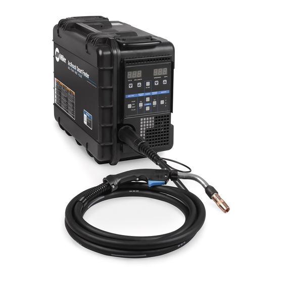
- Page 1 OM-264234G 2016−07 Processes MIG (GMAW) Welding Flux Cored (FCAW) Welding Description Wire Feeder FieldPro Smart Feeder ™ File: MIG (GMAW) For product information, Owner’s Manual translations, and more, visit www.MillerWelds.com...
- Page 2 We know you don’t have time to do it any other way. That’s why when Niels Miller first started building arc welders in 1929, he made sure his products offered long-lasting value and superior quality.
-
Page 3: Table Of Contents
TABLE OF CONTENTS SECTION 1 − SAFETY PRECAUTIONS - READ BEFORE USING ....... . . 1-1. -
Page 5: Declaration Of Conformity
DECLARATION OF CONFORMITY for European Community (CE marked) products. MILLER Electric Mfg. Co., 1635 Spencer Street, Appleton, WI 54914 U.S.A. declares that the product(s) identified in this declaration conform to the essential requirements and provisions of the stated Council Directive(s) and Standard(s). - Page 6 EMF DATA SHEET FOR ARC WELDING POWER SOURCE Product/Apparatus Identification Product Stock Number FIELDPRO SMART FEEDER (DINSE) CE 301177 Compliance Information Summary Applicable regulation Directive 2014/35/EU Reference limits Directive 2013/35/EU, Recommendation 1999/519/EC Applicable standards IEC 62822-1:2016, IEC 62822-2:2016 Intended use for occupational use for use by laymen Non-thermal effects need to be considered for workplace assessment...
-
Page 7: Section 1 − Safety Precautions - Read Before Using
SECTION 1 − SAFETY PRECAUTIONS - READ BEFORE USING som 2015−09 Protect yourself and others from injury — read, follow, and save these important safety precautions and operating instructions. 1-1. Symbol Usage DANGER! − Indicates a hazardous situation which, if Indicates special instructions. - Page 8 D Remove stick electrode from holder or cut off welding wire at FUMES AND GASES can be hazardous. contact tip when not in use. D Wear body protection made from durable, flame−resistant material Welding produces fumes and gases. Breathing (leather, heavy cotton, wool). Body protection includes oil-free these fumes and gases can be hazardous to your clothing such as leather gloves, heavy shirt, cuffless trousers, high health.
-
Page 9: Additional Symbols For Installation, Operation, And Maintenance
1-3. Additional Symbols For Installation, Operation, And Maintenance FIRE OR EXPLOSION hazard. MOVING PARTS can injure. D Do not install or place unit on, over, or near D Keep away from moving parts such as fans. combustible surfaces. D Keep all doors, panels, covers, and guards D Do not install unit near flammables. -
Page 10: California Proposition 65 Warnings
1-4. California Proposition 65 Warnings Welding or cutting equipment produces fumes or gases This product contains chemicals, including lead, known to which contain chemicals known to the State of California to the state of California to cause cancer, birth defects, or other cause birth defects and, in some cases, cancer. -
Page 11: Section 2 − Consignes De Sécurité − Lire Avant Utilisation
SECTION 2 − CONSIGNES DE SÉCURITÉ − LIRE AVANT UTILISATION fre_som_2015−09 Pour écarter les risques de blessure pour vous−même et pour autrui — lire, appliquer et ranger en lieu sûr ces consignes relatives aux précautions de sécurité et au mode opératoire. 2-1. - Page 12 chauffement ou un incendie. Avant de commencer le soudage, vérifier LES PIÈCES CHAUDES peuvent et s’assurer que l’endroit ne présente pas de danger. provoquer des brûlures. D Déplacer toutes les substances inflammables à une distance de D Ne pas toucher à mains nues les parties chaudes. 10,7 m de l’arc de soudage.
-
Page 13: Dangers Supplémentaires En Relation Avec L'installation, Le Fonctionnement Et La Maintenance
D Tenir les bouteilles éloignées des circuits de soudage ou autres LE BRUIT peut endommager l’ouïe. circuits électriques. D Ne jamais placer une torche de soudage sur une bouteille à gaz. Le bruit des processus et des équipements peut affecter l’ouïe. D Une électrode de soudage ne doit jamais entrer en contact avec D Porter des protections approuvées pour les une bouteille. -
Page 14: Proposition Californienne 65 Avertissements
RAYONNEMENT HAUTE LE SOUDAGE À L’ARC risque de FRÉQUENCE (H.F.) risque provoquer des interférences. provoquer des interférences. D L’énergie électromagnétique risque D Le rayonnement haute fréquence (H.F.) peut provoquer des interférences pour l’équipement provoquer des interférences avec les équi- électronique sensible tel que les ordinateurs et l’équipement commandé... -
Page 15: Section 3 − Definitions
SECTION 3 − DEFINITIONS 3-1. Additional Safety Symbols And Definitions Some symbols are found only on CE products. Warning! Watch Out! There are possible hazards as shown by the symbols. Safe1 2012−05 Wear dry insulating gloves. Do not touch electrode (wire) with bare hand. Do not wear wet or damaged gloves. Safe57 2012−05 Protect yourself from electric shock by insulating yourself from work and ground. -
Page 16: Miscellaneous Symbols And Definitions
Do not remove or paint over (cover) the label. Safe20 2012−05 Drive rolls can injure fingers. Safe32 2012−05 Welding wire and drive parts are at welding voltage during operation − keep hands and metal objects away. Safe33 2012−05 Do not use one handle to lift or support unit. Safe31 2012−05 Environmental Protection Use Period (China) Safe123 2016−06... -
Page 17: Section 4 − Specifications
SECTION 4 − SPECIFICATIONS 4-1. Serial Number And Rating Label Location The serial number and rating information for this product is located inside the cover. Use rating label to determine input power requirements and/or rated output. For future reference, write serial number in space provided on back cover of this manual. 4-2. -
Page 18: Environmental Specifications
4-4. Environmental Specifications A. IP Rating IP Rating IP23 This equipment is designed for outdoor use. It may be stored, but is not intended to be used for welding outside during precipitation unless sheltered. IP23 2014−06 B. Information On Electromagnetic Compatibility (EMC) This Class A equipment is not intended for use in residential locations where the electrical power is provided by the public low−... -
Page 19: Section 5 − Installation
SECTION 5 − INSTALLATION 5-1. Selecting a Location Movement Do not move or operate unit where it could tip. Location And Airflow Special installation may be required where gasoline or volatile liquids are present − see NEC Article 511 or CEC Section 20. -
Page 20: Equipment Connection Diagram
5-2. Equipment Connection Diagram Turn Off wire feeder and welding Workpiece 10 Gas Cylinder power source. Work Clamp Use of shielding gas is dependant on wire Welding Power Source Connect work clamp to workpiece. type. Gas Hose Weld Cable To Feeder Gun Trigger Receptacle Shielding gas pressure not to exceed Work Cable To Feeder... -
Page 21: Equipment Setup
5-5. Equipment Setup Associating the FieldProt Smart Feeder PipeWorx FieldProt power source: FEEDER FRONT PANEL Connect the feeder to the welding power source as shown in Section IN USE 5-8. Turn on the welding power source and wire feeder. The welding power source will display the last amperage set point and the wire feeder will display three dashes... -
Page 22: Installing And Aligning Wire Guide And Drive Rolls
5-6. Installing And Aligning Wire Guide And Drive Rolls Installing Wire Guide And Drive Rolls Drive Roll Securing Nut Drive Roll Carrier Turn nut one click until lobes of nut line up with lobes of drive roll carrier. Drive Roll Slide drive roll onto drive roll carrier. -
Page 23: Connecting Welding Gun
5-7. Connecting Welding Gun Turn Off wire feeder and welding power source. Gun Securing Knob Gun Block Gun Power Pin Power Pin Groove Gun Locking Tab Loosen knob, insert gun end into block. Position power pin as close as possible to drive rolls without touching. -
Page 24: Wire Feeder Rear Panel Connections
5-8. Wire Feeder Rear Panel Connections Turn Off power source and Push work cable female connector over Shielding Gas Fitting disconnect both work cables and male connector on feeder and turn 1/4 turn Connect fitting on end of shielding gas hose electrode cable from feeder. -
Page 25: Selecting Cable Sizes
**Weld cable size (AWG) is based on either a 4 volts or less drop or a current density of at least 300 circular mils per ampere. ( ) = mm for metric use ***For distances longer than those shown in this guide, call a factory applications rep. at 920-735-4505 (Miller) or 1-800-332-3281 (Hobart). Ref. S-0007-L 2015−02 Notes... -
Page 26: Installing And Threading Welding Wire
5-11. Installing And Threading Welding Wire Installing Wire And Adjusting Hub Tension Retaining Nut Remove retaining ring and install spool so hub pin fits spool hole. Re- install retaining nut. Adjust retaining nut so only a slight force is needed to turn spool. Do not over tighten tension knob. -
Page 27: Section 6 − Operation
SECTION 6 − OPERATION 6-1. Controls Feeder Front Panel Feeder Setup Panel 264 175-B / 264 178-C Arc Length/Volts Display And Jog Button 14 Wire Type Select Button And Indicators Indicator Trigger Hold On/Off Button In Use Button And Indicator 15 Gas Type Select Button And MIG Type Select Button And Amps/Wire Feed Speed Display And... - Page 28 6-1. Controls (Continued) Arc Length/Volts Display And Indicators This display shows the voltage setting for MIG and FCAW processes (10.0 to 44.0 volts), and it shows the arc length for RMD and Pulsed-MIG processes (−3.0 to +3.0 in 0.1 increments with 0.0 as nominal). The actual arc voltage is displayed while welding and continues to appear for 10 seconds after the welding arc is extinguished.
- Page 29 6-1. Controls (Continued) Memory Card Save Button Press this button to save machine configuration to memory slot. The memory card busy LED illuminates during the following conditions: storage/re- trieval of operator settings, usage of custom MIG type weld process, and firmware upgrades. The memory CARD text will illuminate when custom MIG or TIG type weld process data is currently being used from the memory card.
-
Page 30: Basic Parameters For Smart Feeder
6-2. Basic Parameters For Smart Feeder Steel Wire Size Wire Feed Speed Arc Length Shielding Gas Process in. (mm) IPM (mpm) .035 (0.9) 100-350 w/200 Nominal +3.0 to −3.0 C8 − C15 (2.5-8.9 w/5.1 Nominal) w/zero Nominal .035 (0.9) 100-350 w/200 Nominal +3.0 to −3.0 (2.5-8.9 w/5.1 Nominal) w/zero Nominal... - Page 31 Stainless Steel .035 (0.9) 100-500 w/200 Nominal +3.0 to −3.0 (2.5-19.8 w/5.1 Nominal) w/zero Nominal .035 (0.9) 100-780 w/200 Nominal +3.0 to −3.0 98/2 Ox (2.5-19.8 w/5.1 Nominal) w/zero Nominal .035 (0.9) 100-500 w/200 Nominal +3.0 to −3.0 Tri-A (2.5-19.8 w/5.1 Nominal) w/zero Nominal .040 (1.0) 100-500 w/175 Nominal...
-
Page 32: Restoring Factory Defaults
Flux Core Wire Size Rolling Pipe/In Position Voltage Shielding Gas Process in. (mm) Wire Feed Speed IPM (mpm) 50-500 w/250 Nominal 24.5-32 w/25.0 Nominal Not Dependent Flux Core/GMAW Dependent (1.3-19.8 w/6.4 Nominal)* Note: Arc Length − Length of arc from end of wire to weld puddle. Wire feed speed and voltage are synergic for the RMD and Pulse-MIG processes. -
Page 33: Preflow And Postflow Adjustment
6-5. Preflow And Postflow Adjustment Postflow will not function without an arc initiation. Preflow and Postflow times can be configured for the Wire Feeder outputs. These times are global settings (i.e. all memory slots share the same three preflow and postflow settings; it is not possible to set different postflow times between memory slots). The unit is shipped in the standard configuration (“Std”... -
Page 34: Section 7 − Maintenance & Troubleshooting
SECTION 7 − MAINTENANCE & TROUBLESHOOTING 7-1. Routine Maintenance Disconnect power Maintain more often before maintaining. during severe conditions. n = Check Z = Change ~ = Clean l = Replace Every Months n Z l Replace Damaged n Z l Replace Damaged Gas Hose Or Unreadable Labels n Z l Repair Or Replace Cracked... -
Page 35: Troubleshooting
7-3. Troubleshooting Trouble Remedy Wire does not feed; open-circuit voltage Unit overheated. Allow unit to cool. available. Check gun trigger plug connection. Check gun trigger. See gun Owner’s Manual. Contact nearest Factory Authorized Service Agent. Wire feeds erratically. Readjust drive roll pressure. Clean or replace dirty or worn drive roll (see Section 5-6). -
Page 36: Diagnostic Help Codes
7-4. Diagnostic Help Codes Example Display Display Code Fault Description CbL Err Cable Error Cable arrangement between welding power source and Smart Feeder is preventing proper operation. Un- coil the work and welding cables. Lay the cables straight and close together. Cables that are first laid out straight and close together may then be coiled together. - Page 37 Display Code Fault Description Low Motor Bus Voltage Indicates input primary line voltage is too low. In- crease primary line voltage to at least 90% of speci- fied nominal voltage. If this code to appear on display, contact nearest Factory Authorized Service Agent. Button Is Stuck On Feeder Release button.
- Page 38 Display Code Fault Description Output Current On Channel 3 Too Low Indicates current malfunctions in secondary circuit. If this code appears, contact nearest Factory Authorized Service Agent. Output Current On Channel 4 Too Low Indicates current malfunctions in secondary circuit. If this code appears, contact nearest Factory Authorized Service Agent.
- Page 39 Notes OM-264234 Page 33...
-
Page 40: Section 8 − Electrical Diagram
SECTION 8 − ELECTRICAL DIAGRAM Figure 8-1. Circuit Diagram For Wire Feeder OM-264234 Page 34... - Page 41 257 205-E OM-264234 Page 35...
-
Page 42: Section 9 − Parts List
SECTION 9 − PARTS LIST Hardware is common and not available unless listed. 15 − Figure 9-3 7 − Figure 9-2 25 − Figure 9-6 6 − Figure 9-5 264190-F Figure 9-1. Exploded View Of Smart Feeder OM-264234 Page 36... - Page 43 270418 ..Label, Warning/Miller/FieldPro Smart Feeder Side ....... .
- Page 44 Hardware is common and not available unless listed. 257 707-A / 257 712-TP1 Figure 9-2. Exploded View Of Lower Chassis Assembly OM-264234 Page 38...
- Page 45 Item Diagram Part marking Description Quantity Figure 9-2. Exploded View Of Lower Chassis Assembly ....259291 Panel, Lower Smart Feeder ........
- Page 46 Hardware is common and not available unless listed. 22 − Figure 9-4 257 742-B Figure 9-3. Exploded View Of Center Assembly OM-264234 Page 40...
- Page 47 Item Diagram Part marking Description Quantity Figure 9-3. Exploded View Of Center Assembly ....265464 Nameplate, Assy Smart Feeder Setup Panel (CE) ....
- Page 48 Hardware is common and not available unless listed. 260 792-B Figure 9-4. Exploded View Of Wire Drive Housing Assembly Item Dia. Part Description Mkgs Quantity 260792 Figure 9-4. Exploded View Of Wire Drive Housing Assembly ....233319 Housing, Adapter Gun/Feeder (Machined −...
- Page 49 Hardware is common and not available unless listed. 257 771-B Figure 9-5. Exploded View Of User Interface External Assembly Item Dia. Part Description Mkgs Quantity Figure 9-5. Exploded View Of User Interface External Assembly ....265466 Nameplate, Assy FieldPro Smart Feeder Frnt Pnl (CE) .
- Page 50 Hardware is common and not available unless listed. 271 599-B Figure 9-6. Optional Gas Flow Meter Kit Item Dia. Part Description Mkgs Quantity 301306 Figure 9-6. Optional Gas Flow Meter Kit ....271599 Meter, Flow w/Fittings And Guard (Includes) .
- Page 51 Table 9-1. Drive Roll & Inlet Guide Base selection of drive rolls upon the following recommended usages: 1. V-Grooved rolls for hard wire. 2. U-Grooved rolls for soft and soft shelled cored wires. 3. U-Cogged rolls for extremely soft shelled wires (usually hard surfacing types). 4.
- Page 52 Notes...
- Page 53 Notes...
- Page 54 Notes...
- Page 55 Effective January 1, 2016 (Equipment with a serial number preface of MG or newer) This limited warranty supersedes all previous Miller warranties and is exclusive with no other guarantees or warranties expressed or implied. Warranty Questions? LIMITED WARRANTY − Subject to the terms and conditions below, 6 Months —...
- Page 56 Contact the Delivering Carrier to: File a claim for loss or damage during shipment. For assistance in filing or settling claims, contact your distributor and/or equipment manufacturer’s Transportation Department. © ORIGINAL INSTRUCTIONS − PRINTED IN USA 2016 Miller Electric Mfg. Co. 2016−01...
Need help?
Do you have a question about the FieldPro Smart Feeder CE and is the answer not in the manual?
Questions and answers