Table of Contents
Advertisement
Quick Links
Advertisement
Table of Contents

Related Manuals for AnyTone 5888UV III


Summary of Contents for AnyTone 5888UV III
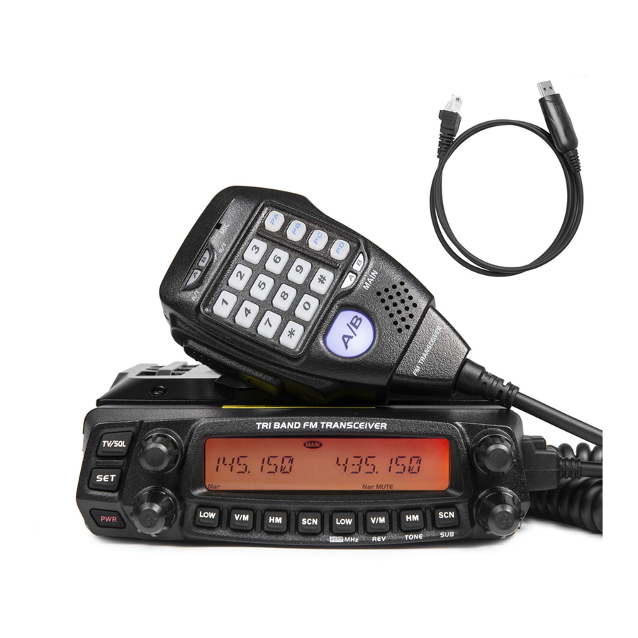
- Page 1 5888UV III TRI-BAND FM TRANSCEIVER USER'S MANUAL...
- Page 2 Nice Housing, Stoutness & Stability, Advanced and Reliable functions, Perfect & Valuable. Approval. TRI Band mobile radio especially designs for drivers and it pursues company philosophy of innovation and practicality.
- Page 3 (2) This device must accept any interference received, including detected coming from the transceiver, turn OFF the power interference that may cause undesired operation. immediately. Contact an Anytone service station or your dealer. Changes or modifications to this unit not expressly approved by the party responsible for compliance could void the user's authority to operate the equipment.
-
Page 4: Table Of Contents
CONTENTS New and Innovative Features ...........1 Scan range Limit ..............12 Frequency Range ..............1 Channel Copy ...............12 Supplied Accessories ...............2 Channel Delete ..............12 General Setting ................13 Supplied Accessories ..............2 Initial Installation ...............3 APO (Automatic Power off) ...........13 Mobile installation ..............3 Automatic offset ..............13 DC Power Cable Connection ..........4 VFO Band lockout ..............14 Antenna Connection ...............6... - Page 5 CONTENTS Priority channel scan .............21 1024 groups DCS Code ............32 Offset frequency Setup ............22 Display mode Setup ..............22 Busy Channel Lockout ............22 Radio's DTMF SELF ID ENQUIRY ........23 5TONE SELF ID ENQUIR ............23 VFO Frequency Linkage ............23 LCD backlight ................23 Keypad backlight brightness ..........24 Calling Record ..............24 AM Function ................24...
-
Page 6: New And Innovative Features
New and Innovative Features Frequency Range RX: 136~174MHz TX: 144~148MHz 222~225MHz 220~260MHz 420~450MHz 400~512MHz... -
Page 7: Supplied Accessories
Supplied Accessories Supplied AcceSSoRieS After carefully unpacking the transceiver, identify the items listed in the table below. We suggest you keep the box and packaging. Transceiver Microphone (QHM-05) Mobile Mounting DC Power Cable with Hardware Kit for Bracket (with DTMF keyboard) Bracket (QMB-01) Fuse Holder(QPL-01) Black screws... -
Page 8: Initial Installation
Initial Installation Determine the appropriate angle of the transceiver, using the 3 Mobile inStAllAtion screw hole positions on the side of the mounting bracket. To install the transceiver, select a safe, convenient location inside your vehicle that minimizes danger to your passengers and yourself while the vehicle is in motion. -
Page 9: Dc Power Cable Connection
Initial Installation Reconnect any wiring removed from the negative terminal. dc poweR cAble connection Locate the power input connector as close to the transceiver as possible. NOTE M o bi l e op e R At io n Black The vehicle battery must have a nominal rating of 12V. Never connect the transceiver to a 24V battery. - Page 10 Initial Installation When the ignition key is turned to ACC or ON(Start) position Connect the DC power cable to the regulated DC power supply with the radio turned off, the power switch illuminates. The and ensure that the polarities are correct. (Red: positive, illumination will be turned off when the ignition key is turned Black:negative).
-
Page 11: Antenna Connection
Initial Installation Re p l Aci n G F uSe S an impedance other than 50Ω reduces the efficiency of the antenna system and can cause interference to nearby broadcast television If the fuse blows, determine the cause, then correct the problem. receivers, radio receivers, and other electronic equipment. -
Page 12: Accessories Connections
Initial Installation AcceSSoRieS connectionS Antenna[QCA-02] Microphone[QHM-04] ex teR nAl Spe Ake R If you plan to use an external speaker, choose a speaker with an impedance of 8Ω. The external speaker jack accepts a 3.5mm (1/8") mono (2-conductor) plug. SP-02 External speaker[SP-02] Mi c Ro pho n e For voice communications, connect a microphone equipped with an... -
Page 13: Getting Acquainted
Getting Acquainted NO. KEY FUNCTION Increase frequency, channel number or setting value. Decrease frequency, channel number or Sub Speaker DOWN setting value. Number Key Input VFO frequency or DTMF dial out etc. Main Speaker A/B band Choose left band or right band as Main band Band indicator The indicator light on for Main band. -
Page 14: Basic Operations
Press key to switch the transceiver ON, the LCD displays "WELCOME ANYTONE", then input FRequency thRouGh MicRophone nuMbeR key display current frequency or channel. In VFO mode, you can input the frequency by the microphone numeric key. -
Page 15: Selecting The Frequency Band
Basic Operations input chAnnel thRouGh MicRophone nuMbeR key Squelch oFF/Squelch oFF MoMentARy In channel mode, you can switch to desired channel by press 3 of the Long press of key can be set up as Squelch Off or Squelch Off microphone numeric keys (001-750). -
Page 16: Shortcut Operations
Shortcut Operations Squelch leVel Setup hypeR MeMoRy chAnnel This function is used to setup the strength of receiving signal, when the In standby, press the left or right volume knob will switch the radio work strength reach a certain level, the calling can be heard, otherwise, the on hyper channel 1 or hyper channel 2. -
Page 17: Channel Scan Skip
Shortcut Operations During the scanning, adjust the Main band selector knob or press chAnnel copy microphone [ UP/DOWN ] key will change the scan direction. In channel mode, turn the selector knob to choose the channel. Press key to exit scan. Hold key until the transceiver prompt a Du and channel number display flashes. -
Page 18: General Setting
General Setting Basic operation steps for Function menu FRequency chAnnel Step Setup Press key to enter function menu. Only in frequency (VFO) mode, this function is valid. Turn selector knob to select Turn the Main band selector knob to choose wanted function. frequency or frequency scanning which is restricted by frequency step size. -
Page 19: Vfo Band Lockout
General Setting cpu clock FRequency chAnGe VFo bAnd lockout When any harmonic or image frequency in the CPU clock disturbs the In VFO mode, when this function is on, the scanning or input of frequency working frequency, turn on this function will cut the disturbing will restricted within the current VFO frequency band. -
Page 20: 5Tone Encode Select
General Setting OFF: Turn off optional signaling 5tone encode Select Press the Main band selector knob or Press key to enter function menu. key to store value and back to function menu. Press Turn the Main band selector knob to or hold selector knob for over 0.5 second to store setup and exit. -
Page 21: Sub Band Display Setup
General Setting Sub bAnd diSplAy Setup dtMF encode Setup Press key to enter function menu. Press to enter function menu Turn the Main band selector knob to Switch the Main band selector knob to choose No. 12 menu. the LCD displays "DSP SUB" choose No.15 menu, the LCD displays Press the Main band selector knob to enter function setup "DTMF W". -
Page 22: Squelch Mode Setup
General Setting coMpAndeR Squelch Mode Setup This transceiver has 5 squelch modes available. Squelch function is used Compander function will decrease the background noise and enhance for increase the level of filtering unwanted signal, and free from disturb. audio clarity, especially in long range communication. Press key to enter function menu. -
Page 23: Tone Burst (Pilot Frequency)
General Setting Press the Main band selector knob to enter function setup. Press the Main band selector knob or key to store value and back to function menu. Press key or hold selector knob for over Switch the Main band selector knob to choose wanted group 0.5 second to store setup and exit. -
Page 24: Keypad Lockout
General Setting the frequency step size changes to 1Mhz, in channel mode, Right short press, shot press this key, the sub band will adjust selector knob will jump 10 channels. display "MAIN" and flashes.In this case, you can setup for sub band without switch between Main band and Sub band. -
Page 25: Squelch Level Setup
General Setting editinG chAnnel nAMe Squelch leVel Setup After edit a name for a channel, if the display mode is channel name, the Press key to enter function menu. will display the name edited in this menu. Otherwise it will display the Turn the Main band selector knob to frequency. -
Page 26: Microphone Pa,Pb, Pc,Pd Key Setup
General Setting S-5: Able to hear the calling when the power meter reach 4 bar. Switch the Mian band selector knob to choose wanted value. S-9: Able to hear the calling when the power meter reach 8 bar. MANUAL: Auto storage is turn off. S-FULL: Able to hear the calling when the AUTO: Auto storeage is turn on. -
Page 27: Offset Frequency Setup
General Setting Press the Main band selector knob to enter function setup. Press the Main band selector knob to enter function setup. Switch the Main band selector knob to choose wanted value. Switch the Main band selector knob to choose wanted value. FREQ: The radio displays channel number + frequency in channel MEN: Channel Scan, the transceiver will mode, if press... -
Page 28: Radio's Dtmf Self Id Enquiry
General Setting Press the Main band selector knob to enter function setup. RAdio'S dtMF SelF id enquiRy Switch the Main band selector knob to choose wanted value. Press key to enter function menu. Available Values: ON, OFF. Switch the selector knob to choose No. 39 Press the Main band selector knob or function. -
Page 29: Keypad Backlight Brightness
General Setting AM Function keypAd bAckliGht bRiGhtneSS Press key to enter function menu. Press key to enter function menu. Turn the Main band selector knob to choose Turn the Main band selector knob to choose No. 50 menu. The LCD displays "AM". No. -
Page 30: Vhf External Speaker Port
General Setting tAlk ARound VhF exteRnAl SpeAkeR poRt With this function on, the transceiver will not able to communicate with When the function setup as external (EXT), in order to hear the calling on another transceiver through a repeater. VHF, user can use sub speaker or connect an external dual track speaker (SP-02). -
Page 31: Password Function
General Setting pASSwoRd Function Press key to enter function menu. Turn the Main band selector knob to choose No.68 menu. The LCD displays "PASSWD". Press the Main band selector knob to enter function setup. Switch the Main band selector knob to choose wanted value. ON: Turn on password function. -
Page 32: Microphone Operation
Microphone Operation TONE: CTCSS/DCS code setup. In standby, press the key TONE function will be able to setup CTCSS/DCS code. When the LCD displays "ENC" and CTCSS frequency, press the [ UP/DOWN ] key to choose CTCSS encode. When the LCD displays "ENC", "DEC" DOWN and CTCSS frequency, press the microphone [ UP/DOWN ] key to choose CTCSS decode. - Page 33 Microphone Operation SCAN: scan function, in standby, press the key "SCAN" function to start channel scan or frequency scan. SQL OFF:Turn off Squelch, in standby, press the key "SQL OFF" function to turn off squelch, you can hear very weak signal, repeat the above function to turn on squelch.
-
Page 34: Memory Banks
10 memory banks are available for memory channel assignments bAnk linkinG to ease in operation of the 5888UV III tri-band radio. You can Memory banks can be linked together for expanded scanning or enable one bank or multible banks through the radio itself. -
Page 35: Maintenance
Maintenance deFAult VAlue FoR FActoRy ReSuMe tRouble ShootinG 5888UV III Possible Causes and Potential Solutions Problem Left band Right band + and - polarities of power connection are (a) Power is on, nothing reversed. Connect red lead to plus terminal VFO frequency 145.15MHz... -
Page 36: Specifications
Specifications General Receiver RX: 136~174MHz Sensitivity ≤0.35μV 220~260MHz (12dB SINAD) 400~512MHz Frequency Range Adjacent Channel TX: 144~148MHz ≥60dB 222~225MHz Selectivity 420~450MHz Audio Response +1~-3dB(0.3~2.55KHz) Number of Channels 750 channels Hum & Noise ≥40dB Audio distortion ≤5% Channel Spacing 12.5KHz Audio power output >... -
Page 37: Attached Chart
Attached Chart 1024 GRoupS dcS code 51 GRoupS ctcSS tone FRequency(hz) 62.5 77.0 91.5 107.2 127.3 151.4 167.9 183.5 199.5 225.7 254.1 Self 67.0 79.7 94.8 110.9 131.8 156.7 171.3 186.2 203.5 229.1 Define 69.3 82.5 97.4 114.8 136.5 159.8 173.8 189.9 206.5 233.6 71.9 85.4 100.0 118.8 141.3 162.2 177.3 192.8 210.7 241.8 74.4 88.5 103.5 123.0 146.2 165.5 179.9 196.6 218.1 250.3... - Page 38 Attached Chart...
Need help?
Do you have a question about the 5888UV III and is the answer not in the manual?
Questions and answers