Advertisement
Introduction
Parts
Installation
Date Code 20160329
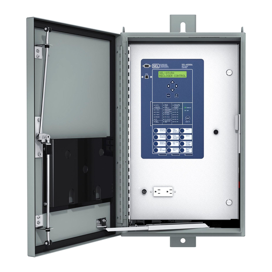
SEL-651RA Installation Instructions for
3-Pin Cable for Input Power
This 3-pin cable for input power provides a three-pin male receptacle that
exits from the bottom of the cabinet. The 3-pin cable for input power is
internally wired to the control module's power supply terminals. Therefore,
the 3-pin cable for input power also supplies power to the outlet and/or any
other accessories effectively connected in parallel with the power supply
terminal. The 3-pin receptacle provides a means (by way of an external cable,
which is not included) to connect input power to the control.
SEL Part Number
SEL-C2261
080-0101
140-0500
140-0740
144-0140
310-0050
Step 1. Install the 3-pin cable for input power in the bottom of the
cabinet in the leftmost hole in the front row. Insert the
receptacle from the inside of the cabinet and the four screws
from the outside. Install the nuts on the screws from the inside
of the cabinet. See Figure 1.
Figure 1 Install Ring Terminal
Description
3-pin cable for input power
5/8 steel wire clamp
4-40 x 1/2" screw
4-40 hex nut
Plastic cap
Zip ties
Quantity
1
2
4
4
1
12
SEL-651RA Recloser Control
Advertisement
Table of Contents

Related Manuals for Sel 651R


Summary of Contents for Sel 651R
- Page 1 SEL-651RA Installation Instructions for 3-Pin Cable for Input Power Introduction This 3-pin cable for input power provides a three-pin male receptacle that exits from the bottom of the cabinet. The 3-pin cable for input power is internally wired to the control module’s power supply terminals. Therefore,...
- Page 2 Step 5. Attach the white wire from the 3-pin cable to the B26 terminal on the control module and the black wire from the 3-pin cable to B21 on the control module. See Figure 4. SEL-651RA Recloser Control Date Code 20160329...
- Page 3 Step 3. Attach the white wire from the 3-pin cable to the N1 fuse on the fuse block for field wiring and the black wire from the 3-pin cable to the L1 fuse on the fuse block for field wiring. See Figure 6. Date Code 20160329 SEL-651RA Recloser Control...
-
Page 4: Wiring Diagrams
3-Pin Wires: Black Wire (A) White Wire (B) Figure 6 Attach Wires to Fuse Block Step 4. Zip tie wires as necessary. Wiring Diagrams Without Fuse Block White Black Ground Stud A B C SEL-651RA Recloser Control Date Code 20160329... - Page 5 With Fuse Block Ground Stud White Black Wiring between fuse block and control module not shown. Date Code 20160329 SEL-651RA Recloser Control...
- Page 6 All brand or product names appearing in this document are the trademark or regis- 2350 NE Hopkins Court • Pullman, WA 99163-5603 U.S.A. tered trademark of their respective holders. No SEL trademarks may be used with- Tel: +1.509.332.1890 • Fax: +1.509.332.7990 out written permission.
Need help?
Do you have a question about the 651R and is the answer not in the manual?
Questions and answers