Table of Contents
Advertisement
Quick Links
Advertisement
Table of Contents

Related Manuals for ABB IRB 260


Summary of Contents for ABB IRB 260
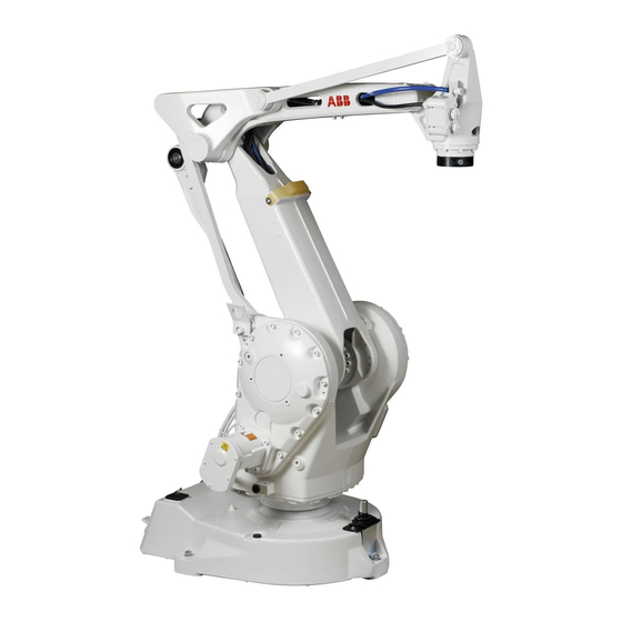
- Page 1 ABB Robotics Product manual IRB 260...
- Page 2 Trace back information: Workspace R13-1 version a6 Checked in 2013-03-31 Skribenta version 1184...
- Page 3 Product manual IRB 260 M2004 Document ID: 3HAC026048-001 Revision: E © Copyright 2006-2013 ABB. All rights reserved.
- Page 4 The information in this manual is subject to change without notice and should not be construed as a commitment by ABB. ABB assumes no responsibility for any errors that may appear in this manual. Except as may be expressly stated anywhere in this manual, nothing herein shall be construed as any kind of guarantee or warranty by ABB for losses, damages to persons or property, fitness for a specific purpose or the like.
-
Page 5: Table Of Contents
Mechanically restricting the working range of axis 1 ........2.4.3 Installation of position switch, axis 1 ............2.4.4 Mechanically restricting the working range of axis 2 ........2.4.5 Mechanically restricting the working range of axis 3 ........3HAC026048-001 Revision: E © Copyright 2006-2013 ABB. All rights reserved. - Page 6 Calibration information Introduction ..................... Calibration methods ................... Calibration scale and correct axis position ............. Calibration movement directions for all axes ............Updating revolution counters ................Checking the calibration position ................3HAC026048-001 Revision: E © Copyright 2006-2013 ABB. All rights reserved.
- Page 7 Spare part lists and exploded views Introduction ...................... Spare parts - overview ..................Spare parts - cover .................... Spare parts - robot IRB 260 ................. Spare parts - axes 1-3 ..................Spare parts - upper arm ..................Spare parts - tilthouse ..................
- Page 8 This page is intentionally left blank...
-
Page 9: Overview Of This Manual
Prerequisites A maintenance/repair/installation craftsman working with an ABB Robot must: • be trained by ABB and have the required knowledge of mechanical and electrical installation/repair/maintenance work. Organization of chapters The manual is organized in the following chapters: Chapter... - Page 10 Safety signals in the manual on page • New safety labels on the manipulators, see Safety symbols on manipulator labels on page • Revised terminology: robot replaced with manipulator. Continues on next page 3HAC026048-001 Revision: E © Copyright 2006-2013 ABB. All rights reserved.
- Page 11 Technical reference manual - Lubrication in gearboxes. For article number see Refer- ences on page • A new SMB unit and battery is introduced, with longer battery lifetime. 3HAC026048-001 Revision: E © Copyright 2006-2013 ABB. All rights reserved.
-
Page 12: Product Documentation, M2004
All documents listed can be ordered from ABB on a DVD. The documents listed are valid for M2004 manipulator systems. Product manuals... - Page 13 Operating manual - Introduction to RAPID • Operating manual - IRC5 with FlexPendant • Operating manual - RobotStudio • Operating manual - Trouble shooting IRC5, for the controller and manipulator. 3HAC026048-001 Revision: E © Copyright 2006-2013 ABB. All rights reserved.
-
Page 14: How To Read The Product Manual
Likewise certain work methods or general information, that is valid for several robot models, can be illustrated with pictures that show a different robot model that the one described in the current manual. 3HAC026048-001 Revision: E © Copyright 2006-2013 ABB. All rights reserved. -
Page 15: Safety
Specific safety information, pointed out in the procedures. How to avoid and eliminate the danger is either described directly in the procedure, or in specific instructions in the section Safety related instructions on page 3HAC026048-001 Revision: E © Copyright 2006-2013 ABB. All rights reserved. -
Page 16: General Safety Information
• stopping functions Safety stops describes different types of • description of emergency stop stops. • description of safety stop • description of safeguarding 3HAC026048-001 Revision: E © Copyright 2006-2013 ABB. All rights reserved. -
Page 17: Safety In The Manipulator System
Limitation of liability Any information given in this manual regarding safety must not be construed as a warranty by ABB that the industrial manipulator will not cause injury or damage even if all safety instructions are complied with. Related information... -
Page 18: Safety Risks
ABB is not liable for damages caused by the use of non-original spare parts and special equipment. ABB is not liable for damages or injuries caused by unauthorized modifications to the manipulator system. - Page 19 Removed cables to the measurement sys- WARNING If the internal cables for the measurement system have been disconnected during repair or maintenance, then the revolution counters must be updated. Continues on next page 3HAC026048-001 Revision: E © Copyright 2006-2013 ABB. All rights reserved.
- Page 20 Do not under any circumstances, deal with the balancing device in any other way than that detailed in the product documentation! For example, attempting to open the balan- cing device is potentially lethal! 3HAC026048-001 Revision: E © Copyright 2006-2013 ABB. All rights reserved.
-
Page 21: Caution - Hot Parts May Cause Burns
Wait until the potentially hot component has cooled if it is to be removed or handled in any other way. 3HAC026048-001 Revision: E © Copyright 2006-2013 ABB. All rights reserved. -
Page 22: Safety Risks Related To Tools/Work Pieces
Unauthorized modifications of the originally delivered manipulator are prohibited. Without the consent of ABB it is forbidden to attach additional parts through welding, riveting, or drilling of new holes into the castings. The strength could be affected. -
Page 23: Safety Risks Related To Pneumatic/Hydraulic Systems
Gravity may cause any parts or objects held by these systems to drop. • Dump valves should be used in case of emergency. • Shot bolts should be used to prevent tools, etc., from falling due to gravity. 3HAC026048-001 Revision: E © Copyright 2006-2013 ABB. All rights reserved. -
Page 24: Safety Risks During Operational Disturbances
If the working process is interrupted, extra care must be taken due to risks other than those associated with regular operation. Such an interruption may have to be rectified manually. 3HAC026048-001 Revision: E © Copyright 2006-2013 ABB. All rights reserved. -
Page 25: Risks Associated With Live Electric Parts
The power supply unit for additional tools, or special power supply units for the machining process. • The external voltage connected to the controller remains live even when the robot is disconnected from the mains. • Additional connections. Continues on next page 3HAC026048-001 Revision: E © Copyright 2006-2013 ABB. All rights reserved. - Page 26 Tools, material handling devices, etc., may be live even if the robot system is in the OFF position. Power supply cables which are in motion during the working process may be damaged. 3HAC026048-001 Revision: E © Copyright 2006-2013 ABB. All rights reserved.
-
Page 27: Safety Actions
(see the section Robot motion in the Product specification). Also consider the maximum possible impact caused by a breaking or malfunctioning rotating tool or other device fitted to the manipulator. 3HAC026048-001 Revision: E © Copyright 2006-2013 ABB. All rights reserved. -
Page 28: Fire Extinguishing
1 Safety 1.2.4.2 Fire extinguishing 1.2.4.2 Fire extinguishing Note Use a CARBON DIOXIDE (CO ) extinguisher in the event of a fire in the manipulator system (manipulator or controller)! 3HAC026048-001 Revision: E © Copyright 2006-2013 ABB. All rights reserved. -
Page 29: Emergency Release Of The Manipulator's Arm
Increased injury Before releasing the brakes, make sure that the weight of the arms does not increase the pressure on the trapped person, further increasing any injury! 3HAC026048-001 Revision: E © Copyright 2006-2013 ABB. All rights reserved. -
Page 30: Brake Testing
3 Check that the axis maintains its position. If the manipulator does not change position as the motors are switched off, then the brake function is adequate. 3HAC026048-001 Revision: E © Copyright 2006-2013 ABB. All rights reserved. -
Page 31: Risk Of Disabling Function "Reduced Speed 250 Mm/S
1.2.4.5 Risk of disabling function "Reduced speed 250 mm/s" Note Do not change Transm gear ratio or other kinematic system parameters from the FlexPendant or a PC. This will affect the safety function "Reduced speed 250 mm/s". 3HAC026048-001 Revision: E © Copyright 2006-2013 ABB. All rights reserved. -
Page 32: Safe Use Of The Flexpendant
The hold-to-run function can only be used in manual mode. How to operate the hold-to-run function for IRC5 is described in Operating manual - IRC5 with FlexPendant. 3HAC026048-001 Revision: E © Copyright 2006-2013 ABB. All rights reserved. -
Page 33: Work Inside The Manipulator's Working Range
NEVER, under any circumstances, stay beneath any of the manipulator’s axes! There is always a risk that the manipulator will move unexpectedly when manipulator axes are moved using the enabling device or during other work inside the manipulator’s working range. 3HAC026048-001 Revision: E © Copyright 2006-2013 ABB. All rights reserved. -
Page 34: Safety Stops
Emergency stop should not be used for normal program stops as this causes extra, unnecessary wear on the manipulator. For how to perform normal program stops, see section Stopping programs in Operating manual - IRC5 with FlexPendant. Continues on next page 3HAC026048-001 Revision: E © Copyright 2006-2013 ABB. All rights reserved. - Page 35 Dual Cabinet Controller). There can also be other types of emergency stops on your manipulator. Consult your plant or cell documentation to see how your manipulator system is configured. 3HAC026048-001 Revision: E © Copyright 2006-2013 ABB. All rights reserved.
-
Page 36: Safety Related Instructions
ELECTROSTATIC Warns for electrostatic hazards which could result DISCHARGE (ESD) in severe damage to the product. xx0200000023 Continues on next page 3HAC026048-001 Revision: E © Copyright 2006-2013 ABB. All rights reserved. - Page 37 1.3.1 Safety signals in the manual Continued Symbol Designation Significance NOTE Describes important facts and conditions. xx0100000004 Describes where to find additional information or how to do an operation in an easier way. xx0100000098 3HAC026048-001 Revision: E © Copyright 2006-2013 ABB. All rights reserved.
-
Page 38: Safety Symbols On Manipulator Labels
Prohibition Used in combinations with other symbols. xx0900000839 Continues on next page 3HAC026048-001 Revision: E © Copyright 2006-2013 ABB. All rights reserved. - Page 39 Pressing this button will release the brakes. This means that the manipulator arm can fall down. xx0900000808 Tip risk when loosening bolts The manipulator can tip over if the bolts are not securely fastened. xx0900000810 Continues on next page 3HAC026048-001 Revision: E © Copyright 2006-2013 ABB. All rights reserved.
- Page 40 Risk of crush injuries. xx0900000817 Heat Risk of heat that can cause burns. xx0900000818 Moving robot The robot can move unexpectedly. xx0900000819 xx1000001141 Brake release buttons xx0900000820 xx1000001140 Continues on next page 3HAC026048-001 Revision: E © Copyright 2006-2013 ABB. All rights reserved.
- Page 41 Mechanical stop xx0900000824 No mechanical stop xx1000001144 Stored energy Warns that this part contains stored energy. Used in combination with Do not dismantle symbol. xx0900000825 Continues on next page 3HAC026048-001 Revision: E © Copyright 2006-2013 ABB. All rights reserved.
- Page 42 Symbol Description Pressure Warns that this part is pressurized. Usually contains additional text with the pressure level. xx0900000826 Shut off with handle Use the power switch on the controller. xx0900000827 3HAC026048-001 Revision: E © Copyright 2006-2013 ABB. All rights reserved.
-
Page 43: Danger - Moving Manipulators Are Potentially Lethal
The hold-to-run function is used in manual mode, not in automatic mode. Make sure no personnel are present within the working range of the manipulator be- fore pressing the start button. 3HAC026048-001 Revision: E © Copyright 2006-2013 ABB. All rights reserved. -
Page 44: Danger - First Test Run May Cause Injury Or Damage
Pay special attention to the function of the part previously serviced Collision risks CAUTION When programming the movements of the manipulator always check potential collision risks before the first test run. 3HAC026048-001 Revision: E © Copyright 2006-2013 ABB. All rights reserved. -
Page 45: Danger - Make Sure That The Main Power Has Been Switched Off
Switch off the main switch for the controller. xx0600003255 Elimination, Single Cabinet Controller Action Note/illustration Switch off the main switch on the controller cabinet. xx0600002782 A: Main switch Continues on next page 3HAC026048-001 Revision: E © Copyright 2006-2013 ABB. All rights reserved. - Page 46 Note/illustration Switch off the main switch on the Drive Module. xx0600002783 K: Main switch, Drive Module Switch off the main switch on the Control A: Main switch, Control Module Module. 3HAC026048-001 Revision: E © Copyright 2006-2013 ABB. All rights reserved.
-
Page 47: Warning - The Unit Is Sensitive To Esd
The location of the wrist strap button is shown in the following illustration. IRC5 The wrist strap button is located in the top right corner. xx0500002171 Wrist strap button Continues on next page 3HAC026048-001 Revision: E © Copyright 2006-2013 ABB. All rights reserved. - Page 48 Panel Mounted Controller xx0600003249 Panel Mounted Control Module Panel Mounted Drive Module Wrist strap button NOTE! When not used, the wrist strap must always be attached to the wrist strap button. 3HAC026048-001 Revision: E © Copyright 2006-2013 ABB. All rights reserved.
-
Page 49: Warning - Safety Risks During Handling Of Batteries
Risk of fire or explosion. page Use safety glasses when handling the batteries. In the event of leakage, wear gloves and chemical apron. In the event of fire, use self-contained breathing apparatus. 3HAC026048-001 Revision: E © Copyright 2006-2013 ABB. All rights reserved. -
Page 50: Warning - Safety Risks During Work With Gearbox Lubricants (Oil Or Grease)
Do not present in the gearbox, causing overfill the gearbox when filling. lubricant to spray from the xx0100000002 opening. Possible pressure build-up in gearbox Continues on next page 3HAC026048-001 Revision: E © Copyright 2006-2013 ABB. All rights reserved. - Page 51 Specified amount de- been drained from the gearbox. pends on drained volume 3HAC026048-001 Revision: E © Copyright 2006-2013 ABB. All rights reserved.
- Page 52 This page is intentionally left blank...
-
Page 53: Installation And Commissioning
Safety on page 15 before performing any installation work. Note If the IRB 260 is connected to power, always make sure that the robot is connected to protective earth before starting any installation work! For more information see: • Product manual - IRC5 •... -
Page 54: Unpacking
It also contains information useful during later re-installation of the robot. Checking the pre-requisites for installation Installation craftsmen working with an ABB robot must: • be trained by ABB and have the required knowledge of mechanical and electrical installation/maintenance/repair work • conform to all national and local codes. - Page 55 Force z 3500 ± 1100 N 3500 ± 2300 N Torque xy ± 2100 Nm ± 3900 Nm Torque z ± 650 Nm ± 950 Nm§ Continues on next page 3HAC026048-001 Revision: E © Copyright 2006-2013 ABB. All rights reserved.
- Page 56 Maximum tilt 5° The limit for the maximum payload on the robot is reduced if the robot is tilted from 0°. Contact ABB for further information about accept- able loads. Minimum resonance 30 Hz frequency...
-
Page 57: Working Range
The extreme positions of the robot are specified at the tool flange center (dimensions in mm). xx0500001926 Position at mechanical stop Position at maximum working range, axis 2 Tool flange center Continues on next page 3HAC026048-001 Revision: E © Copyright 2006-2013 ABB. All rights reserved. - Page 58 +400º to -400º (default) +150 revolutions to -150 revolutions max. The default working range for axis 6 can be extended by changing parameter values in the software (option Advanced Motion is required). 3HAC026048-001 Revision: E © Copyright 2006-2013 ABB. All rights reserved.
-
Page 59: Risk Of Tipping/Stability
The shipping position is the most stable position. Do not change the robot position before securing it to the foundation! WARNING The robot is likely to be mechanically unstable if not secured to the foundation! 3HAC026048-001 Revision: E © Copyright 2006-2013 ABB. All rights reserved. -
Page 60: On-Site Installation
Lifting capacity: 500 kg. Lifting slings Lifting chains, 3 pcs Lengths: • axis 2: 950 mm • axis 3: 920 mm • upper arm: 680 mm Continues on next page 3HAC026048-001 Revision: E © Copyright 2006-2013 ABB. All rights reserved. - Page 61 The lifting slings are attached to the robot as shown in the figure below. The axis positions are specified below the figure. xx0500002140 Axis 2 po- -10º sition: Axis 3 po- +35º sition: Continues on next page 3HAC026048-001 Revision: E © Copyright 2006-2013 ABB. All rights reserved.
- Page 62 The lifting chains are attached to the robot as shown in the figure below. The axis positions are specified below the figure. xx0500002141 Axis 2 position: -28º Axis 3 position: +17º Lifting chain, axis 2 Continues on next page 3HAC026048-001 Revision: E © Copyright 2006-2013 ABB. All rights reserved.
- Page 63 The robot weighs 340 kg! All lifting equip- ment used must be sized accordingly! Attach the lifting equipment to the robot as shown in the previous figures and lift the robot. 3HAC026048-001 Revision: E © Copyright 2006-2013 ABB. All rights reserved.
-
Page 64: Manually Releasing The Brakes
Be careful not to interchange the 24 VDC and 0V pins! If they are mixed up, damage can be caused to a resistor diode and to the system board. Continues on next page 3HAC026048-001 Revision: E © Copyright 2006-2013 ABB. All rights reserved. - Page 65 R1.MP, at the robot base. Supply: • +24 V on pin B8 • 0 V on pin C10 xx0200000167 Release the brakes with the brake release unit as detailed in the previous procedure. 3HAC026048-001 Revision: E © Copyright 2006-2013 ABB. All rights reserved.
-
Page 66: Orienting And Securing The Robot
Suitable screws, lightly lubricated: M16 x 50 Quality Quality 8.8 Suitable washer: Thickness: 3 mm Outer diameter: 30 mm Inner diameter: 17 mm Tightening torque: 190 Nm Continues on next page 3HAC026048-001 Revision: E © Copyright 2006-2013 ABB. All rights reserved. - Page 67 Cross section is shown in the following figure. xx0200000181 Cross section, guide sleeve hole The figure below shows the cross section of the guide sleeve holes (from previous figure): xx0200000182 Continues on next page 3HAC026048-001 Revision: E © Copyright 2006-2013 ABB. All rights reserved.
- Page 68 Two guide sleeves can be fitted to the two rear bolt holes to allow the same robot to be remounted without re-adjusting the program. Equipment Art. no. Guide sleeves 2151 0024-169 3HAC026048-001 Revision: E © Copyright 2006-2013 ABB. All rights reserved.
-
Page 69: Fitting Equipment On The Robot And Robot Dimensions
This section shows the dimensions and available mounting holes on the robot. Main dimensions xx0500001928 At maximum working range axis 3 Mounting hole for safety lamp Mounting hole for external air hose Continues on next page 3HAC026048-001 Revision: E © Copyright 2006-2013 ABB. All rights reserved. - Page 70 Fitting equipment on the robot xx0500002102 M8 (3x) Depth 16 mm, R=77 M8 (3x) Depth 16 mm, R=92 Max. 35 kg total The rear side of the robot Continues on next page 3HAC026048-001 Revision: E © Copyright 2006-2013 ABB. All rights reserved.
- Page 71 2 Installation and commissioning 2.3.4 Fitting equipment on the robot and robot dimensions Continued Turning radius, axis 2 xx0500001929 Continues on next page 3HAC026048-001 Revision: E © Copyright 2006-2013 ABB. All rights reserved.
- Page 72 2 Installation and commissioning 2.3.4 Fitting equipment on the robot and robot dimensions Continued Turning disk, dimensions The figure below shows the mounting holes available for fitting equipment on the turning disk. xx0500001932 3HAC026048-001 Revision: E © Copyright 2006-2013 ABB. All rights reserved.
-
Page 73: Loads
Operating manual - IRC5 with FlexPendant (M2004) Stop time and braking distances Robot motor brake performance depends on any loads attached. For information about brake performance, read the product specification for the robot. 3HAC026048-001 Revision: E © Copyright 2006-2013 ABB. All rights reserved. -
Page 74: Load Diagram
2.3.6 Load diagram 2.3.6 Load diagram Load diagram, IRB 260-30/1.5 The figure below shows the maximum permitted load mounted on the robot tool flange at different positions (center of gravity). xx0500002100 3HAC026048-001 Revision: E © Copyright 2006-2013 ABB. All rights reserved. -
Page 75: Installation Of Signal Lamp (Option)
Signal lamp on robot The signal lamp is installed on the upper arm, as shown in the figure below. xx0500002125 Indicator lamp Lamp holder O-ring Cable gland Continues on next page 3HAC026048-001 Revision: E © Copyright 2006-2013 ABB. All rights reserved. - Page 76 Shown in the figure Signal lamp on robot screws. on page Make sure that the lamp is lit when the controller is in MOTORS ON mode. 3HAC026048-001 Revision: E © Copyright 2006-2013 ABB. All rights reserved.
-
Page 77: Restricting The Working Range
This section describes how to install hardware that restricts the working range. Note Adjustments must also be made in the robot configuration software (system parameters). References to relevant manuals are included in the installation procedures. 3HAC026048-001 Revision: E © Copyright 2006-2013 ABB. All rights reserved. -
Page 78: Mechanically Restricting The Working Range Of Axis 1
The working range of axis 1 can be restricted within the area from 50º to 140º as shown in the figure below. The restrictions are made by fitting two extra stops to the robot base and adjusting the system parameter configuration. xx0500002105 Continues on next page 3HAC026048-001 Revision: E © Copyright 2006-2013 ABB. All rights reserved. - Page 79 Make a copy of the drill template, enclosed with The template is also shown in the the mechanical stop. figure Drill template on page 83 scale 1:1. Continues on next page 3HAC026048-001 Revision: E © Copyright 2006-2013 ABB. All rights reserved.
- Page 80 Deformed movable stops and/or additional stops as well as deformed attachment screws must also be replaced after a hard collision. Continues on next page 3HAC026048-001 Revision: E © Copyright 2006-2013 ABB. All rights reserved.
- Page 81 2 x 4º, which corresponds to the width of the stop pin (at the frame). Continues on next page 3HAC026048-001 Revision: E © Copyright 2006-2013 ABB. All rights reserved.
- Page 82 2.4.2 Mechanically restricting the working range of axis 1 Continued Hidden stiffening ribs and forbidden drilling sector xx0600002647 Drilling not allowed inside this sector! Center lines for the hidden stiffening ribs Continues on next page 3HAC026048-001 Revision: E © Copyright 2006-2013 ABB. All rights reserved.
- Page 83 2 Installation and commissioning 2.4.2 Mechanically restricting the working range of axis 1 Continued Drill template xx0200000207 3HAC026048-001 Revision: E © Copyright 2006-2013 ABB. All rights reserved.
-
Page 84: Installation Of Position Switch, Axis 1
Position switch Attachment screws, position switch (2 pcs for each switch) M4 x 16 Holder ring Attachment screws, holder ring, 6 pcs: M8 x 12 Continues on next page 3HAC026048-001 Revision: E © Copyright 2006-2013 ABB. All rights reserved. - Page 85 Fit the complete bracket to the base of Shown in the figure Location of position the robot with the two attachment screws. switch, axis 1 on page Continues on next page 3HAC026048-001 Revision: E © Copyright 2006-2013 ABB. All rights reserved.
- Page 86 The system parameters that must be tions (system parameter configuration) changed (Upper joint bound and Lower joint to correspond to the mechanical limita- bound) are described in Technical reference tions. manual - System parameters. 3HAC026048-001 Revision: E © Copyright 2006-2013 ABB. All rights reserved.
-
Page 87: Mechanically Restricting The Working Range Of Axis 2
Technical reference manual - System Art. no. is specified in section parameters References on page Standard toolkit The content is defined in the section Standard tools on page 225. Continues on next page 3HAC026048-001 Revision: E © Copyright 2006-2013 ABB. All rights reserved. - Page 88 • A: Attachment holes for the short stop (spacer) • B: Attachment holes for the long stop (spacer) Fit the dampers to the mechanical stops. Continues on next page 3HAC026048-001 Revision: E © Copyright 2006-2013 ABB. All rights reserved.
- Page 89 If the mechanical stop pin is deformed after a hard collision, it must be replaced! Deformed movable stops and/or addition- al stops as well as deformed attachment screws must also be replaced after a hard collision. 3HAC026048-001 Revision: E © Copyright 2006-2013 ABB. All rights reserved.
-
Page 90: Mechanically Restricting The Working Range Of Axis 3
Technical reference manual - System Art. no. is specified in section parameters References on page Standard toolkit The content is defined in the section Standard tools on page 225. Continues on next page 3HAC026048-001 Revision: E © Copyright 2006-2013 ABB. All rights reserved. - Page 91 If the mechanical stop pin is deformed after a hard collision, it must be replaced! Deformed movable stops and/or additional stops as well as deformed attachment screws must also be replaced after a hard collision. 3HAC026048-001 Revision: E © Copyright 2006-2013 ABB. All rights reserved.
-
Page 92: Electrical Connections
2.5.1 Connectors on robot 2.5 Electrical connections 2.5.1 Connectors on robot Connectors on the robot The figure below shows all connections of the robot cabling, including the customer connections. xx0500002434 3HAC026048-001 Revision: E © Copyright 2006-2013 ABB. All rights reserved. -
Page 93: Robot Cabling And Connection Points
Robot cable, signals Cable Art. no. Robot cable signal, shielded: 7 m 3HAC7998-1 Robot cable signal, shielded: 15 m 3HAC7998-2 Robot cable signal, shielded: 22 m 3HAC7998-3 Continues on next page 3HAC026048-001 Revision: E © Copyright 2006-2013 ABB. All rights reserved. - Page 94 Customer cable, power-signal, 7 m 3HAC8183-1 R1.CP/CS Customer cable, power-signal, 15 m 3HAC8183-2 R1.CP/CS Customer cable, power-signal, 22 m 3HAC8183-3 R1.CP/CS Customer cable, power-signal, 30 m 3HAC8183-4 R1.CP/CS 3HAC026048-001 Revision: E © Copyright 2006-2013 ABB. All rights reserved.
-
Page 95: Maintenance
Safety on page 15 before performing any service work! Note If the IRB 260 is connected to power, always make sure that the IRB 260 is connected to protective earth before starting any maintenance work! For more information see: •... -
Page 96: Maintenance Schedule
3.2.1 Specification of maintenance intervals Introduction The intervals are specified in different ways depending on the type of maintenance activity to be carried out and the working conditions of the IRB 260: • Calendar time: specified in months regardless of whether the system is running or not. -
Page 97: Maintenance Schedule
The recommendation to avoid an unsynchronized robot is to keep the power to the controller turned on until the battery is to be replaced. See the replacement instruction for more details. 3HAC026048-001 Revision: E © Copyright 2006-2013 ABB. All rights reserved. -
Page 98: Inspection Activities
2945 4489-16 Item B in the figure. Calibration label 3HAC024307-001 Item D in the figure. Instruction plate 3HAC025469-001 Item H in the figure. Lifting of robot. Continues on next page 3HAC026048-001 Revision: E © Copyright 2006-2013 ABB. All rights reserved. - Page 99 Turn off all electric power, hydraulic and pneumatic pressure supplies to the robot! Inspect that all labels are fitted to the robot. Replace Shown in the figure Location of them if damaged or missing. labels on page 3HAC026048-001 Revision: E © Copyright 2006-2013 ABB. All rights reserved.
-
Page 100: Changing Activities
Location of gearboxes The figure shows the location of the gearboxes. xx0500001950 Gearbox, axis 1 Gearbox, axis 2 Gearbox, axis 3 Gearbox, axis 6 Continues on next page 3HAC026048-001 Revision: E © Copyright 2006-2013 ABB. All rights reserved. - Page 101 10. In order to always get the latest information of updates about lubrication in gearboxes, always check on ABB Library for the latest revision of the manual. A new revision will be published on ABB Library immediatly after any updates.
-
Page 102: Oil Change, Gearbox Axis 6 (Wrist Unit)
The procedure below details how to drain the oil from the gearbox, axis 6. Action Note DANGER Turn off all electric power, hydraulic and pneu- matic pressure supplies to the robot! Continues on next page 3HAC026048-001 Revision: E © Copyright 2006-2013 ABB. All rights reserved. - Page 103 Type and amount of oil in gearboxes on page 101. Oil plugs are shown in the figure Location of oil plugs, gearbox on page 102. Refit the oil plug. 3HAC026048-001 Revision: E © Copyright 2006-2013 ABB. All rights reserved.
-
Page 104: Replacement Of Smb Battery
See Operating manual - IRC5 with FlexPendant for instructions. WARNING See instructions for batteries, WARNING - Safety risks during handling of batteries on page Continues on next page 3HAC026048-001 Revision: E © Copyright 2006-2013 ABB. All rights reserved. - Page 105 Location of SMB battery unit The SMB battery unit is located inside the robot base, as shown in the figure below. xx0300000067 SMB battery (2-pole battery contact) SMB battery cable Continues on next page 3HAC026048-001 Revision: E © Copyright 2006-2013 ABB. All rights reserved.
- Page 106 Do not replace the battery contact! Equipment Spare part no. Note Battery pack (2-pole battery 3HAC16831-1 Lithium battery. contact) Can only be used with SMB unit 3HAC17396-1 containing SMB board 3HAC031851-001. Continues on next page 3HAC026048-001 Revision: E © Copyright 2006-2013 ABB. All rights reserved.
- Page 107 Spare part no. is specified in Required equipment on page 106. Update the revolution counters! Detailed in the section Updating revolu- tion counters on page 211. 3HAC026048-001 Revision: E © Copyright 2006-2013 ABB. All rights reserved.
-
Page 108: Cleaning Activities
Cleaning with water and steam Cleaning methods that can be used for ABB robots with protection Standard, Foundry Plus, Wash and Foundry Prime. Equipment, etc. Note Vacuum cleaner Cloth with mild detergent •... - Page 109 Never point the water jet at connectors, joints, sealings, or gaskets! • Never use compressed air to clean the robot! • Never use solvents that are not approved by ABB to clean the robot! • Never spray from a distance closer than 0.4 meters! •...
- Page 110 This page is intentionally left blank...
-
Page 111: Repair
Make sure to read through the chapter Safety on page 15 before commencing any service work. Note If the IRB 260 is connected to power, always make sure that the IRB 260 is connected to earth before starting any repair work. For more information see: •... -
Page 112: General Procedures
The test is complete. Spray suspected leak areas with leak detection spray. Bubbles indicate a leak. When the leak has been localized, take the necessary measures to correct the leak. 3HAC026048-001 Revision: E © Copyright 2006-2013 ABB. All rights reserved. -
Page 113: Mounting Instructions For Bearings
• During operation, the bearing should be filled to 70-80% of the available volume. Continues on next page 3HAC026048-001 Revision: E © Copyright 2006-2013 ABB. All rights reserved. - Page 114 Grease the different types of bearings as following description: • Grooved ball bearings must be filled with grease from both sides. • Tapered roller bearings and axial needle bearings must be greased in the split condition. 3HAC026048-001 Revision: E © Copyright 2006-2013 ABB. All rights reserved.
-
Page 115: Mounting Instructions For Seals
Mount the seal correctly with a mounting tool. Never hammer directly on the seal as this may result in leakage. Continues on next page 3HAC026048-001 Revision: E © Copyright 2006-2013 ABB. All rights reserved. - Page 116 If the flange surfaces are defective, the parts may not be used because leakage could occur. Clean the surfaces properly in accordance with the recommendations of ABB. Distribute the sealing compound evenly over the surface, preferably with a brush. Tighten the screws evenly when fastening the flange joint.
-
Page 117: Complete Robot
Equipment, etc. Spare part no. Art. no. Note Cable unit, axes 1-3 3HAC025725-001 Includes: • cabling • motor covers • attachment screws • gaskets, motor 1-3 Continues on next page 3HAC026048-001 Revision: E © Copyright 2006-2013 ABB. All rights reserved. - Page 118 (B). xx0200000399 Disconnect the connectors R1.MP1-3 and R2.BU1-3 inside the base. Disconnect all the earth cables on the R1.M1-3 cable from the back of the cover. Continues on next page 3HAC026048-001 Revision: E © Copyright 2006-2013 ABB. All rights reserved.
- Page 119 Remove the cover of the motors 1-3. Continues on next page 3HAC026048-001 Revision: E © Copyright 2006-2013 ABB. All rights reserved.
- Page 120 Refit the cover of the motors, axes 1, 2 and 3, with the five attachment screws. Refit the upper bracket securing the cables to the arm house, using the two attachment screws. Continues on next page 3HAC026048-001 Revision: E © Copyright 2006-2013 ABB. All rights reserved.
- Page 121 Art. numbers are specified in Required equipment on page 117. Connect the connectors R2.FB 1-3 to the connection R2.SMB1-4 (C) on the SMB unit. xx0200000400 R2.SMB R2.SMB3-6 R2.SMB1-4 Continues on next page 3HAC026048-001 Revision: E © Copyright 2006-2013 ABB. All rights reserved.
- Page 122 Make sure all safety requirements are met when performing the first test run. These are further detailed in the section DANGER - First test run may cause injury or damage! on page 3HAC026048-001 Revision: E © Copyright 2006-2013 ABB. All rights reserved.
-
Page 123: Replacement Of Cable Unit, Axis
Connector at UL lamp: R3.H1 and R3.H2. Customer connectors / air hose are located on the opposite side of the wrist unit: R2.CS, R2.CP and R2.CAIR Power cable Signal cable Continues on next page 3HAC026048-001 Revision: E © Copyright 2006-2013 ABB. All rights reserved. - Page 124 Location of cable R2.BU4-6 from the base. Also disconnect unit, axis 6 on page 123. the customer cables and the air hose. Disconnect all earth cables. Continues on next page 3HAC026048-001 Revision: E © Copyright 2006-2013 ABB. All rights reserved.
- Page 125 Disconnect the connectors at the upper arm: • at the UL lamp • at motor, axis 6 (R3.MP6 and R3.FB6) • at customer connections (R2.CS, R2.CP and R2.CAIR). Continues on next page 3HAC026048-001 Revision: E © Copyright 2006-2013 ABB. All rights reserved.
- Page 126 R2.SMB R2.SMB3-6 R2.SMB1-4 Refit the SMB unit to the bracket by tighten- ing the nuts (D). Reconnect the battery cable (A), if discon- nected. xx0200000398 Continues on next page 3HAC026048-001 Revision: E © Copyright 2006-2013 ABB. All rights reserved.
- Page 127 Make sure all safety requirements are met when performing the first test run. These are further detailed in the section DANGER - First test run may cause injury or damage! on page 3HAC026048-001 Revision: E © Copyright 2006-2013 ABB. All rights reserved.
-
Page 128: Upper Arm
Taper roller bearing (2 pcs) Sealing ring with dust lip Lock nut (2 pcs) Protection hood (2 pcs) VK cover (2 pcs) M6 screws, including washers (4 pcs) Continues on next page 3HAC026048-001 Revision: E © Copyright 2006-2013 ABB. All rights reserved. - Page 129 (included in the toolkit for service). Note The parts cannot be ordered separately, but are included in the complete toolkit! The article numbers are only given for identification. Continues on next page 3HAC026048-001 Revision: E © Copyright 2006-2013 ABB. All rights reserved.
- Page 130 (included in the toolkit for service). Note The parts cannot be ordered separately, but are included in the complete toolkit! The article numbers are only given for identification. Continues on next page 3HAC026048-001 Revision: E © Copyright 2006-2013 ABB. All rights reserved.
- Page 131 (included in the toolkit for service). Note The parts cannot be ordered separately, but are included in the complete toolkit! The article numbers are only given for identification. Continues on next page 3HAC026048-001 Revision: E © Copyright 2006-2013 ABB. All rights reserved.
- Page 132 (included in the toolkit for service). Note The parts cannot be ordered separately, but are included in the complete toolkit! The article numbers are only given for identification. Continues on next page 3HAC026048-001 Revision: E © Copyright 2006-2013 ABB. All rights reserved.
- Page 133 (included in the toolkit for service). Note The parts cannot be ordered separately, but are included in the complete toolkit! The article numbers are only given for identification. Continues on next page 3HAC026048-001 Revision: E © Copyright 2006-2013 ABB. All rights reserved.
- Page 134 (included in the toolkit for service). Note The parts cannot be ordered separately, but are included in the complete toolkit! The article numbers are only given for identification. Continues on next page 3HAC026048-001 Revision: E © Copyright 2006-2013 ABB. All rights reserved.
- Page 135 Dismantling tool, tilthouse shaft on service. page 129. Art. no. for the toolkit is specified in Required equipment on page 129. Continues on next page 3HAC026048-001 Revision: E © Copyright 2006-2013 ABB. All rights reserved.
- Page 136 Lubricate the seating (A) of the bearings and Art. no. is specified in Required sealing rings in the upper arm with bearing equipment on page 129. grease. xx0500002580 Continues on next page 3HAC026048-001 Revision: E © Copyright 2006-2013 ABB. All rights reserved.
- Page 137 Mounting tool, toolkit for service. tilthouse shaft on page 132. Place the tilthouse in mounting position and insert the shaft through the upper arm and tilt- house. Continues on next page 3HAC026048-001 Revision: E © Copyright 2006-2013 ABB. All rights reserved.
- Page 138 Shown in the figure Location of shaft lubrication holes. and bearings on page 128. Spare part no. for washer is specified Required equipment on page 129. Continues on next page 3HAC026048-001 Revision: E © Copyright 2006-2013 ABB. All rights reserved.
- Page 139 Make sure all safety requirements are met when performing the first test run. These are further detailed in the section DANGER - First test run may cause injury or damage! on page 3HAC026048-001 Revision: E © Copyright 2006-2013 ABB. All rights reserved.
-
Page 140: Replacement Of Turning Disk
Standard toolkit The content is defined in the section Standard tools on page 225. Calibration Pendulum 3HAC15716-1 Complete kit that also in- toolkit cludes operating manual. Continues on next page 3HAC026048-001 Revision: E © Copyright 2006-2013 ABB. All rights reserved. - Page 141 Calibration is detailed in a separate calibration manual enclosed with the calibration tools. General calibration information is included in the section Calibration information on page 207. Continues on next page 3HAC026048-001 Revision: E © Copyright 2006-2013 ABB. All rights reserved.
- Page 142 Make sure all safety requirements are met when performing the first test run. These are further detailed in the section DANGER - First test run may cause injury or damage! on page 3HAC026048-001 Revision: E © Copyright 2006-2013 ABB. All rights reserved.
-
Page 143: Replacement Of Complete Upper Arm
The upper arm is located as shown in the figure below. A more detailed view of the component and its position may be found in section Robot IRB 260, exploded view 1 of 2 on page 242 in part 2 of the Product manual. - Page 144 Remove the linkage. Detailed in sections: • Removal, upper rod on page 151 • Removal, lower rod on page 154 • Removal, link on page 159 Continues on next page 3HAC026048-001 Revision: E © Copyright 2006-2013 ABB. All rights reserved.
- Page 145 (fit the auxiliary shaft to the upper arm shaft). Assembly of the tool is shown in the figure Press tool, link on page 158. Continues on next page 3HAC026048-001 Revision: E © Copyright 2006-2013 ABB. All rights reserved.
- Page 146 Art. no. is specified in Required equip- with grease. ment on page 143. Insert the cabling into the upper arm while placing the arm into mounting position. Continues on next page 3HAC026048-001 Revision: E © Copyright 2006-2013 ABB. All rights reserved.
- Page 147 Reused screws may be used, providing they are lubricated as detailed in the section Screw joints on page 221 before fitting. Tighten the flanged bolts. Tightening torque: 10 Nm. Continues on next page 3HAC026048-001 Revision: E © Copyright 2006-2013 ABB. All rights reserved.
- Page 148 Refit the linkage. Detailed in sections: • Refitting, link on page 160 • Refitting, upper rod on page 152 • Refitting, lower rod on page 156 Continues on next page 3HAC026048-001 Revision: E © Copyright 2006-2013 ABB. All rights reserved.
- Page 149 Make sure all safety requirements are met when performing the first test run. These are further detailed in the section DANGER - First test run may cause injury or damage! on page 3HAC026048-001 Revision: E © Copyright 2006-2013 ABB. All rights reserved.
-
Page 150: Replacement Of Linkage - Upper Rod
Sealing ring (2 pcs) Support washer (4 pcs) Lock nut (2 pcs) Link Required equipment Equipment Spare part no. Art no. Note Parallel rod upper 3HAC024575-001 Continues on next page 3HAC026048-001 Revision: E © Copyright 2006-2013 ABB. All rights reserved. - Page 151 Remove them from the link arm! Remove the support washers and the sealing rings. Remove residual grease. Continues on next page 3HAC026048-001 Revision: E © Copyright 2006-2013 ABB. All rights reserved.
- Page 152 Make sure all safety requirements are met when performing the first test run. These are further detailed in the section DANGER - First test run may cause injury or damage! on page 3HAC026048-001 Revision: E © Copyright 2006-2013 ABB. All rights reserved.
-
Page 153: Replacing The Linkage - Lower Rod
The lower rod is located as shown in the figure below. xx0600002617 Lower rod Sealing ring (2 pcs) Support washer (4 pcs) Lock nut (2 pcs) Link Continues on next page 3HAC026048-001 Revision: E © Copyright 2006-2013 ABB. All rights reserved. - Page 154 Note DANGER Turn off all: • electric power supply • hydraulic pressure supply • air pressure supply to the robot, before entering the robot working area. Continues on next page 3HAC026048-001 Revision: E © Copyright 2006-2013 ABB. All rights reserved.
- Page 155 Remove them from the rod! Remove the inner support washers and the sealing/spacer rings. Remove residual grease. Continues on next page 3HAC026048-001 Revision: E © Copyright 2006-2013 ABB. All rights reserved.
- Page 156 Make sure all safety requirements are met when performing the first test run. These are further detailed in the section DANGER - First test run may cause injury or damage! on page 3HAC026048-001 Revision: E © Copyright 2006-2013 ABB. All rights reserved.
-
Page 157: Replacement Of Linkage - Link
Bearing (shown as complete bearing, but the outer race should already be mounted inside the seating prior to refitting of link) Lock nut Protection hood VK cover Screws and washers for lubrication and venting holes (3 pcs) Continues on next page 3HAC026048-001 Revision: E © Copyright 2006-2013 ABB. All rights reserved. - Page 158 (included in the toolkit for service). Note The parts cannot be ordered separately, but are included in the complete toolkit! The article numbers are only given for identification. Continues on next page 3HAC026048-001 Revision: E © Copyright 2006-2013 ABB. All rights reserved.
- Page 159 • Removal, upper rod on page 151. • Removal, lower rod on page 154. Remove the center screw and washer in the hole for filling grease. Continues on next page 3HAC026048-001 Revision: E © Copyright 2006-2013 ABB. All rights reserved.
- Page 160 The fitting is further detailed in sec- tion Refitting, upper arm on page 146. Lubricate the shaft end with bearing grease. Specified in Required equipment on page 158. Continues on next page 3HAC026048-001 Revision: E © Copyright 2006-2013 ABB. All rights reserved.
- Page 161 Make sure all safety requirements are met when performing the first test run. These are further detailed in the section DANGER - First test run may cause injury or damage! on page 3HAC026048-001 Revision: E © Copyright 2006-2013 ABB. All rights reserved.
-
Page 162: Lower Arm
A more detailed view of the component and its position may be found in section Axes 1-3, spare part view 2 on page 247 in part 2 of the Product manual. xx0500002548 Lower arm Sealing ring Continues on next page 3HAC026048-001 Revision: E © Copyright 2006-2013 ABB. All rights reserved. - Page 163 Detailed in section Removal, upper arm on page 144. CAUTION The robot lower arm weighs without any additional equipment fitted. All lifting accessories used must be sized accordingly! Continues on next page 3HAC026048-001 Revision: E © Copyright 2006-2013 ABB. All rights reserved.
- Page 164 Note DANGER Turn off all electric power, hydraulic and pneumatic pressure supplies to the robot! Move the damper and calibration marking to the new lower arm. Continues on next page 3HAC026048-001 Revision: E © Copyright 2006-2013 ABB. All rights reserved.
- Page 165 Make sure all safety requirements are met when performing the first test run. These are further detailed in the section DANGER - First test run may cause injury or damage! on page 3HAC026048-001 Revision: E © Copyright 2006-2013 ABB. All rights reserved.
-
Page 166: Replacement Of Parallel Bar
Equipment, etc. Spare part no. Art. no. Note Parallel bar complete 3HAC025714-001 Includes: • spherical roller bear- ings • bearing sealings Spherical roller bearing 3HAA2167-12 2 pcs Continues on next page 3HAC026048-001 Revision: E © Copyright 2006-2013 ABB. All rights reserved. - Page 167 CAUTION The robot upper arm weighs without any addition- al equipment fitted. All lifting accessories used must be sized accord- ingly! Continues on next page 3HAC026048-001 Revision: E © Copyright 2006-2013 ABB. All rights reserved.
- Page 168 Refit the parallel bar, using the mounting Art. no. is specified in Required equip- tool, parallel bar. ment on page 166. Note Press by hand! Fit new bearing sealings to the bearings. Continues on next page 3HAC026048-001 Revision: E © Copyright 2006-2013 ABB. All rights reserved.
- Page 169 Make sure all safety requirements are met when performing the first test run. These are further detailed in the section DANGER - First test run may cause injury or damage! on page 3HAC026048-001 Revision: E © Copyright 2006-2013 ABB. All rights reserved.
-
Page 170: Frame And Base
Note that the robot is shown with the SMB cover already removed! xx0200000451 Cable, battery/SMB board Battery pack (2-pole battery contact) Serial measurement board Lock nuts Continues on next page 3HAC026048-001 Revision: E © Copyright 2006-2013 ABB. All rights reserved. - Page 171 It is important that the SMB unit uses the correct battery. Make sure to order the correct spare parts. Do not replace the battery contact! Equipment Spare part no. Art. no. Note Gasket, cover 3HAC3200-1 Must always be replaced! Continues on next page 3HAC026048-001 Revision: E © Copyright 2006-2013 ABB. All rights reserved.
- Page 172 Other tools and proced- These procedures include ures may be required. See references to the tools re- references to these proced- quired. ures in the step-by-step instructions below. Continues on next page 3HAC026048-001 Revision: E © Copyright 2006-2013 ABB. All rights reserved.
- Page 173 4 Repair 4.6.1 Replacement of SMB unit Continued SMB unit, layout xx0600002645 Connector R2.SMB4-6 Connector R2.SMB1-3 Connector R2.SMB1-2 (external axis) Connector R2.SMB Connector R2.G (battery unit) Continues on next page 3HAC026048-001 Revision: E © Copyright 2006-2013 ABB. All rights reserved.
- Page 174 Remove the rear cover plate (A) from the base by unscrewing the attachment screws (B). xx0200000399 Remove the SMB battery. Detailed in section Replacement, SMB battery on page 107. Continues on next page 3HAC026048-001 Revision: E © Copyright 2006-2013 ABB. All rights reserved.
- Page 175 Art. no. is specified in Required equip- ment on page 171. Update the revolution counters! Detailed in the section Updating revolu- tion counters on page 211. 3HAC026048-001 Revision: E © Copyright 2006-2013 ABB. All rights reserved.
-
Page 176: Replacement Of Brake Release Unit
Unscrew the six attachment screws of the brake release unit on the outside of the base. Disconnect the cable from the brake release unit and remove the unit from the base. Continues on next page 3HAC026048-001 Revision: E © Copyright 2006-2013 ABB. All rights reserved. - Page 177 Make sure all safety requirements are met when performing the first test run. These are further detailed in the section DANGER - First test run may cause injury or damage! on page 3HAC026048-001 Revision: E © Copyright 2006-2013 ABB. All rights reserved.
-
Page 178: Replacement Of Parallel Arm
Standard toolkit The content is defined in the section Standard tools on page 225. Calibration Pendulum toolkit 3HAC15716-1 Complete kit that also in- cludes operating manual. Continues on next page 3HAC026048-001 Revision: E © Copyright 2006-2013 ABB. All rights reserved. - Page 179 Remove the parallel bar. Detailed in section Removal, par- allel bar on page 167. Remove the parallel arm by removing its eight at- tachment screws and washers. Continues on next page 3HAC026048-001 Revision: E © Copyright 2006-2013 ABB. All rights reserved.
- Page 180 Fit the complete parallel arm to the robot with the 8 pcs; M10x60. eight attachment screws and washers. Tightening torque: 72 Nm. Continues on next page 3HAC026048-001 Revision: E © Copyright 2006-2013 ABB. All rights reserved.
- Page 181 Make sure all safety requirements are met when performing the first test run. These are further detailed in the section DANGER - First test run may cause injury or damage! on page 3HAC026048-001 Revision: E © Copyright 2006-2013 ABB. All rights reserved.
-
Page 182: Motors
Axes 1-3, spare part view 1 on page 246. xx0200000465 Cover Connection box Attachment screws and washers, motor (4 pcs) Motor axis 1 Correct orientation of holes Continues on next page 3HAC026048-001 Revision: E © Copyright 2006-2013 ABB. All rights reserved. - Page 183 C: Connection box Remove the connection box by unscrewing its Shown in the figure Location of three attachment screws and plain washers. motor, axis 1 on page 182. Continues on next page 3HAC026048-001 Revision: E © Copyright 2006-2013 ABB. All rights reserved.
- Page 184 Shown in the figure below. Rotate the motor shaft several turns, using the measuring tool. There must always be some backlash, meaning that the shaft should go easy to rotate! Continues on next page 3HAC026048-001 Revision: E © Copyright 2006-2013 ABB. All rights reserved.
- Page 185 Calibration is detailed in a separate calibration manual enclosed with the calibration tools. General calibration information is included in the section Calibration information on page 207. Continues on next page 3HAC026048-001 Revision: E © Copyright 2006-2013 ABB. All rights reserved.
- Page 186 Make sure all safety requirements are met when performing the first test run. These are further detailed in the section DANGER - First test run may cause injury or damage! on page 3HAC026048-001 Revision: E © Copyright 2006-2013 ABB. All rights reserved.
-
Page 187: Replacement Of Motor, Axis 2
Attachment screws, cover (5 pcs) Cover Connection box Gasket Motor, axis 2 Attachment screws, motor (4 pcs) O-ring Correct orientation of holes on top of motor Continues on next page 3HAC026048-001 Revision: E © Copyright 2006-2013 ABB. All rights reserved. - Page 188 Use a marker pen to mark out the position of the motor, if the same motor is to be refitted. Continues on next page 3HAC026048-001 Revision: E © Copyright 2006-2013 ABB. All rights reserved.
- Page 189 Also see the orientation holes on the motor cover, shown in the figure Location of motor, axis 2 on page 187. Continues on next page 3HAC026048-001 Revision: E © Copyright 2006-2013 ABB. All rights reserved.
- Page 190 Shown in the figure Location of mo- three attachment screws and plain washers. tor, axis 2 on page 187. Make sure that the gasket is fitted properly! Continues on next page 3HAC026048-001 Revision: E © Copyright 2006-2013 ABB. All rights reserved.
- Page 191 Make sure all safety requirements are met when performing the first test run. These are further detailed in the section DANGER - First test run may cause injury or damage! on page 3HAC026048-001 Revision: E © Copyright 2006-2013 ABB. All rights reserved.
-
Page 192: Replacement Of Motor, Axis 3
247. xx0200000471 Attachment screws, cover Cover Connection box Gasket Motor, axis 2 Attachment screws, motor (4 pcs) O-ring Correct orientation of holes on top of motor Continues on next page 3HAC026048-001 Revision: E © Copyright 2006-2013 ABB. All rights reserved. - Page 193 3 on page 192. Use a marker pen to mark out the position of the motor, if the same motor is to be refitted. Continues on next page 3HAC026048-001 Revision: E © Copyright 2006-2013 ABB. All rights reserved.
- Page 194 Also see the orientation holes on the motor cover, shown in the figure Location of motor, axis 3 on page 192. Tighten the four screws lightly. Tightening torque: 2 Nm. Continues on next page 3HAC026048-001 Revision: E © Copyright 2006-2013 ABB. All rights reserved.
- Page 195 Refit the connection box with the three attach- Shown in the figure Location of motor, ment screws and plain washers. axis 3 on page 192. Make sure that the gasket is fitted properly! Continues on next page 3HAC026048-001 Revision: E © Copyright 2006-2013 ABB. All rights reserved.
- Page 196 Make sure all safety requirements are met when performing the first test run. These are further detailed in the section DANGER - First test run may cause injury or damage! on page 3HAC026048-001 Revision: E © Copyright 2006-2013 ABB. All rights reserved.
-
Page 197: Replacement Of Motor, Axis 6
Standard tools on page 225. Calibration Pendulum 3HAC15716-1 Complete kit that also in- toolkit cludes operating manual. Circuit diagram See the chapter Circuit dia- gram on page 261. Continues on next page 3HAC026048-001 Revision: E © Copyright 2006-2013 ABB. All rights reserved. - Page 198 Calibration is detailed in a separ- ate calibration manual enclosed with the calibration tools. General calibration information is included in the section Calibration information on page 207. Continues on next page 3HAC026048-001 Revision: E © Copyright 2006-2013 ABB. All rights reserved.
- Page 199 Make sure all safety requirements are met when performing the first test run. These are further de- tailed in the section DANGER - First test run may cause injury or damage! on page 3HAC026048-001 Revision: E © Copyright 2006-2013 ABB. All rights reserved.
-
Page 200: Gearboxes
Other tools and procedures These procedures include may be required. See refer- references to the tools re- ences to these procedures quired. in the step-by-step instruc- tions below. Continues on next page 3HAC026048-001 Revision: E © Copyright 2006-2013 ABB. All rights reserved. - Page 201 Place the gearbox unit upside-down on a table or similar surface. Fit the base to the gearbox unit and secure with 12 pcs; M12x50. Tightening torque: the 12 screws and washers. 54 Nm. Continues on next page 3HAC026048-001 Revision: E © Copyright 2006-2013 ABB. All rights reserved.
- Page 202 Make sure all safety requirements are met when performing the first test run. These are further detailed in the section DANGER - First test run may cause injury or damage! on page 3HAC026048-001 Revision: E © Copyright 2006-2013 ABB. All rights reserved.
-
Page 203: Replacement Of Gearbox, Axis 6
Other tools and proced- These procedures include ures may be required. references to the tools re- See references to these quired. procedures in the step- by-step instructions be- low. Continues on next page 3HAC026048-001 Revision: E © Copyright 2006-2013 ABB. All rights reserved. - Page 204 Calibration is detailed in a separate calibration manual enclosed with the calibration tools. General calibration information is included in the section Calibration information on page 207. Continues on next page 3HAC026048-001 Revision: E © Copyright 2006-2013 ABB. All rights reserved.
- Page 205 Make sure all safety requirements are met when performing the first test run. These are further detailed in the section DANGER - First test run may cause injury or damage! on page 3HAC026048-001 Revision: E © Copyright 2006-2013 ABB. All rights reserved.
- Page 206 This page is intentionally left blank...
-
Page 207: Calibration Information
The resolver values are changed If resolver values are changed, the robot must be recalibrated using the calibration methods supplied by ABB. Calibrate the robot carefully with standard calibration. The different methods are briefly described in the section Calibration methods on page 208 , and further detailed in separate calibration manuals. -
Page 208: Calibration Methods
Calibration Pendulum - standard method Calibration Pendulum is the standard method for calibration of all ABB robots (except IRB 6400R, IRB 640, IRB 1400H, and IRB 4400S) and is also the most accurate method for the standard type of calibration. It is the recommended method in order to achieve proper performance. -
Page 209: Calibration Scale And Correct Axis Position
Mechanical stop of axis 3 Calibration mark on calibration plate, axis 3 Calibration plate and marking, axis 6 Punch, axis 1, 3HAB8223-1 Punch, axis 2, 3HAB8223-1 (1 marking) 3HAC026048-001 Revision: E © Copyright 2006-2013 ABB. All rights reserved. -
Page 210: Calibration Movement Directions For All Axes
Positive directions are shown in the graphic below. This is normally handled by the robot calibration software. Calibration movement directions, 4 axes Note! The graphic shows an IRB 260. The positive direction is the same for all 4-axis robots xx0500001927 3HAC026048-001 Revision: E ©... -
Page 211: Updating Revolution Counters
Use this procedure to store the revolution counter setting with the FlexPendant (IRC5). Action On the ABB menu, tap Calibration. All mechanical units connected to the system are shown with their calibration status. Continues on next page 3HAC026048-001 Revision: E © Copyright 2006-2013 ABB. All rights reserved. - Page 212 If a revolution counter is incorrectly updated, it will cause incorrect manipulator posi- tioning, which in turn may cause damage or injury! Check the calibration position very carefully after each update. See Checking the calibration position on page 213. 3HAC026048-001 Revision: E © Copyright 2006-2013 ABB. All rights reserved.
-
Page 213: Checking The Calibration Position
Check that the calibration marks for the Calibration scale and correct axis pos- axes align correctly. If they do not, update ition on page 209, and Updating revolution the revolution counters! counters on page 211. 3HAC026048-001 Revision: E © Copyright 2006-2013 ABB. All rights reserved. - Page 214 This page is intentionally left blank...
-
Page 215: Decommissioning
Also note that: • Spills can form a film on water surfaces causing damage to organisms. Oxygen transfer could also be impaired. • Spillage can penetrate the soil causing ground water contamination. 3HAC026048-001 Revision: E © Copyright 2006-2013 ABB. All rights reserved. - Page 216 This page is intentionally left blank...
-
Page 217: Reference Information
7 Reference information 7.1 Introduction 7 Reference information 7.1 Introduction General This chapter includes general information, complementing the more specific information in the different procedures in the manual. 3HAC026048-001 Revision: E © Copyright 2006-2013 ABB. All rights reserved. -
Page 218: Applicable Safety Standards
Safety of machinery - General requirements for the design and construction of fixed and movable guards Other standards Standard Description ANSI/RIA R15.06 Safety requirements for industrial robots and robot systems Continues on next page 3HAC026048-001 Revision: E © Copyright 2006-2013 ABB. All rights reserved. - Page 219 7.2 Applicable safety standards Continued Standard Description ANSI/UL 1740 Safety standard for robots and robotic equipment (option 429-1) CAN/CSA Z 434-03 Industrial robots and robot Systems - General safety require- ments (option 429-1) 3HAC026048-001 Revision: E © Copyright 2006-2013 ABB. All rights reserved.
-
Page 220: Unit Conversion
3.28 ft. 39.37 in Weight 1 kg 2.21 lb. Weight 0.035 ounces Pressure 1 bar 100 kPa 14.5 psi Force 0.225 lbf Moment 1 Nm 0.738 lbf-ft Volume 0.264 US gal 3HAC026048-001 Revision: E © Copyright 2006-2013 ABB. All rights reserved. -
Page 221: Screw Joints
UNBRAKO screws UNBRAKO is a special type of screw recommended by ABB for certain screw joints. It features special surface treatment (Gleitmo as described below) and is extremely resistant to fatigue. - Page 222 Molycote 1000, Gleitmo 603 or equivalent with allen head screws. Dimension Tightening torque (Nm) Tightening torque (Nm) Class 10.9, lubricated Class 12.9, lubricated Continues on next page 3HAC026048-001 Revision: E © Copyright 2006-2013 ABB. All rights reserved.
- Page 223 The following table specifies the recommended standard tightening torque for water and air connectors when one or both connectors are made of brass. Dimension Tightening torque Nm - Tightening torque Nm - Tightening torque Nm - Nominal Min. Max. 3HAC026048-001 Revision: E © Copyright 2006-2013 ABB. All rights reserved.
-
Page 224: Weight Specifications
All components exceeding 22 kg (50 lbs) are highlighted in this way. To avoid injury, ABB recommends the use of a lifting accessory when handling components with a weight exceeding 22 kg. A wide range of lifting accessories and devices are available for each manipulator model. -
Page 225: Standard Tools
Socket head cap no: 5, socket 1/2" bit L 20 mm Socket head cap no: 6, socket 1/2" bit L 20 mm Socket head cap no: 8, socket 1/2" bit L 20 mm Small cutting plier T-handle with ball head 3HAC026048-001 Revision: E © Copyright 2006-2013 ABB. All rights reserved. -
Page 226: Special Tools
Press washer 3HAC023963-007 Hex socket head cap screw 9ADA183-25 2 pcs, M6 x 25 Connection rod M16, length= 400 mm 3HAC5507-1 Sleeve 3HAC023963-027 D= 70 mm Continues on next page 3HAC026048-001 Revision: E © Copyright 2006-2013 ABB. All rights reserved. - Page 227 Connecting rod 3HAC023081-003 Mxx, length= xx mm Press housing 3HAC024097-002 Auxiliary shaft 3HAC024097-005 Hex socket head cap screw 9ADA183-24 2 pcs, M6 x 12 Distance 3HAC023062-001 Continues on next page 3HAC026048-001 Revision: E © Copyright 2006-2013 ABB. All rights reserved.
- Page 228 Press tool, link. Assembly is shown in the figure Press tool, link on page 234. Press sleeve, art. no. specified in the table Special tools on page 226. Continues on next page 3HAC026048-001 Revision: E © Copyright 2006-2013 ABB. All rights reserved.
- Page 229 (included in the toolkit for service). Note The parts cannot be ordered separately, but are included in the complete toolkit! The article numbers are only given for identification. Continues on next page 3HAC026048-001 Revision: E © Copyright 2006-2013 ABB. All rights reserved.
- Page 230 (included in the toolkit for service). Note The parts cannot be ordered separately, but are included in the complete toolkit! The article numbers are only given for identification. Continues on next page 3HAC026048-001 Revision: E © Copyright 2006-2013 ABB. All rights reserved.
- Page 231 (included in the toolkit for service). Note The parts cannot be ordered separately, but are included in the complete toolkit! The article numbers are only given for identification. Continues on next page 3HAC026048-001 Revision: E © Copyright 2006-2013 ABB. All rights reserved.
- Page 232 (included in the toolkit for service). Note The parts cannot be ordered separately, but are included in the complete toolkit! The article numbers are only given for identification. Continues on next page 3HAC026048-001 Revision: E © Copyright 2006-2013 ABB. All rights reserved.
- Page 233 (included in the toolkit for service). Note The parts cannot be ordered separately, but are included in the complete toolkit! The article numbers are only given for identification. Continues on next page 3HAC026048-001 Revision: E © Copyright 2006-2013 ABB. All rights reserved.
- Page 234 (included in the toolkit for service). Note The parts cannot be ordered separately, but are included in the complete toolkit! The article numbers are only given for identification. Continues on next page 3HAC026048-001 Revision: E © Copyright 2006-2013 ABB. All rights reserved.
- Page 235 The following table specifies the calibration equipment needed when calibrating the robot with the Calibration Pendulum method. Description Art. no. Note Calibration Pendulum toolkit 3HAC15716-1 Complete kit that also includes operating manual. 3HAC026048-001 Revision: E © Copyright 2006-2013 ABB. All rights reserved.
-
Page 236: Lifting Accessories And Lifting Instructions
The use of each piece of lifting accessories is not detailed in the activity procedure, but in the instruction delivered with each piece of lifting accessories. This implies that the instructions delivered with the lifting accessories should be stored for later reference. 3HAC026048-001 Revision: E © Copyright 2006-2013 ABB. All rights reserved. -
Page 237: Spare Part Lists And Exploded Views
8 Spare part lists and exploded views 8.1 Introduction 8 Spare part lists and exploded views 8.1 Introduction Definitions This chapter specifies all spare parts and replacement articles of the robot. 3HAC026048-001 Revision: E © Copyright 2006-2013 ABB. All rights reserved. -
Page 238: Spare Parts - Overview
Position switch axis 1 3HAC12062-3 Includes three switches. Stop axis 1 3HAB 7298-1 Signal lamp 3HAC025254-001 Material set 3HAC24116-001 Spare parts - material set cabling axis 6 on page 258 3HAC026048-001 Revision: E © Copyright 2006-2013 ABB. All rights reserved. -
Page 239: Spare Parts - Cover
M5X15 Push button guard 3HAC2744-1 Recommended spare part. Signal cable SMB 3HAC7819-1 Recommended spare part. Adaptor customer cabling 3HAB7328-1 Adaptor power cabling 3HAC2809-1 Cover pushbuttons 3HAC3197-1 Continues on next page 3HAC026048-001 Revision: E © Copyright 2006-2013 ABB. All rights reserved. - Page 240 8 Spare part lists and exploded views 8.3 Spare parts - cover Continued Cover, spare part view xx0500002436 3HAC026048-001 Revision: E © Copyright 2006-2013 ABB. All rights reserved.
-
Page 241: Spare Parts - Robot Irb 260
Robot IRB 260, spare part list The items specified below are shown in the figures Robot IRB 260, exploded view 1 of 2 on page 242 Robot IRB 260, exploded view 2 of 2 on page 243. Item Description Spare part no. - Page 242 M6x20 Steel 12.9 Gleitmo Protection hood 2522 2101-17 Lifting eye 2179 090-25 Plain washer 9ADA312-9 13x24x2,5 Bearing sealing 3HAC10089-2 Robot IRB 260, exploded view 1 of 2 xx0500001936 Continues on next page 3HAC026048-001 Revision: E © Copyright 2006-2013 ABB. All rights reserved.
- Page 243 8 Spare part lists and exploded views 8.4 Spare parts - robot IRB 260 Continued Robot IRB 260, exploded view 2 of 2 xx0500001937 3HAC026048-001 Revision: E © Copyright 2006-2013 ABB. All rights reserved.
-
Page 244: Spare Parts - Axes 1-3
Recommended spare part. Replacement is detailed in section Replacement of motor, axis 2 on page 187. 14,700 Lubricating oil 11712016-604 165g Bearing grease 3HAB3537-1 Shell Alvania WR2 Continues on next page 3HAC026048-001 Revision: E © Copyright 2006-2013 ABB. All rights reserved. - Page 245 Parallel bar complete 3HAC025714-001 Spherical roller bearing 3HAA2167-12 Included in the complete parallel bar. Torx pan head tapp. screw 21212477-331 Parallel arm complete 3HAC025727-001 Lower arm 3HAC025729-001 Continues on next page 3HAC026048-001 Revision: E © Copyright 2006-2013 ABB. All rights reserved.
- Page 246 8 Spare part lists and exploded views 8.5 Spare parts - axes 1-3 Continued Axes 1-3, spare part view 1 xx0500002047 Continues on next page 3HAC026048-001 Revision: E © Copyright 2006-2013 ABB. All rights reserved.
- Page 247 117. Bottom plate 3HAC2828-1 Gasket 3HAC4554-1 Sealing 3HAC4113-1 Recommended spare part. Bracket 3HAB5923-1 Holder for cable guide 3HAB3299-1 Cable guide 3HAB5924-1 Spring 3HAB3662-1 Cover 3HAC025749-1 Continues on next page 3HAC026048-001 Revision: E © Copyright 2006-2013 ABB. All rights reserved.
- Page 248 Hex socket head cap screw 9ADA183-34 M8x12 Torx pan head roll. screw 9ADA629-44 M5x12 Cable straps, outdoors 21662055-1 Coupling 3HAB3333-20 2 ml Locking liquid Loctite 542 Continues on next page 3HAC026048-001 Revision: E © Copyright 2006-2013 ABB. All rights reserved.
- Page 249 Dimension/Note Protective hood 25222101-8 Gasket 3HAC4419-1 Gasket 3HAB7160-1 1 ml Flange sealing 12340011-116 Adhesive tape 11699198-301 Bracket 3HAB5921-1 Parallel pin, hardened 3HAC3785-3 Sealing 3HAC5479-4 Profile 18661903-1 Continues on next page 3HAC026048-001 Revision: E © Copyright 2006-2013 ABB. All rights reserved.
- Page 250 8 Spare part lists and exploded views 8.5 Spare parts - axes 1-3 Continued Axes 1-3, spare part view 3 xx0500002084 Continues on next page 3HAC026048-001 Revision: E © Copyright 2006-2013 ABB. All rights reserved.
- Page 251 The housing must be removed from the cabling for foundry option Conductors from R2.BU, R2.BU1-3, R2.BU4-6 and PE conductors under strap Option: internal connectors Option: external connectors Continues on next page 3HAC026048-001 Revision: E © Copyright 2006-2013 ABB. All rights reserved.
- Page 252 8 Spare part lists and exploded views 8.5 Spare parts - axes 1-3 Continued Axes 1-3, spare part view 5 xx0500002086 3HAC026048-001 Revision: E © Copyright 2006-2013 ABB. All rights reserved.
-
Page 253: Spare Parts - Upper Arm
Recommended spare part. Torx pan head screw 9ADA618-53 M6x8 Washer 3HAC020537-001 D=6,4/12 T=1,6 Recommended spare part. Locking liquid 60 g Bearing grease 3HAB3537-1 Shell Alvania WR2 Continues on next page 3HAC026048-001 Revision: E © Copyright 2006-2013 ABB. All rights reserved. - Page 254 8 Spare part lists and exploded views 8.6 Spare parts - upper arm Continued Upper arm, exploded view xx0500001934 3HAC026048-001 Revision: E © Copyright 2006-2013 ABB. All rights reserved.
-
Page 255: Spare Parts - Tilthouse
9ADA183-25 Plain washer 9ADA312-6 O-ring 3HAB3772-16 Recommended spare part. 70 ml Lubricating oil, Kyodo Yushi 3HAC032140-001 TMO 150 Torx counters.head screw 9ADA624-69 M8x20 Washer 21524411-1 13,5x18x1,5 Continues on next page 3HAC026048-001 Revision: E © Copyright 2006-2013 ABB. All rights reserved. - Page 256 8 Spare part lists and exploded views 8.7 Spare parts - tilthouse Continued Tilthouse, exploded view xx0500001935 3HAC026048-001 Revision: E © Copyright 2006-2013 ABB. All rights reserved.
-
Page 257: Spare Parts - Linkage
Linkage, spare part list Item Description Spare part no. Dimension Parallel rod, lower 3HAC024576-001 Parallel rod upper 3HAC024575-001 Radial Seal 35x62x7 Link machining Taper roller bearing Needle bearing 3HAB6432-1 Linkage, exploded view xx0500001933 3HAC026048-001 Revision: E © Copyright 2006-2013 ABB. All rights reserved. -
Page 258: Spare Parts - Material Set Cabling Axis 6
Square washer Torx pan head screw M5x16 Steel 8.8 Fe/ZN 5c Cable bracket tilt house 3HAC025783-001 Recommended spare part. Torx pan head screw 9ADA618-23 M3x8 Steel 8.8-A2F Continues on next page 3HAC026048-001 Revision: E © Copyright 2006-2013 ABB. All rights reserved. - Page 259 8 Spare part lists and exploded views 8.9 Spare parts - material set cabling axis 6 Continued Material set cabling axis 6, spare part view xx0500002438 3HAC026048-001 Revision: E © Copyright 2006-2013 ABB. All rights reserved.
- Page 260 This page is intentionally left blank...
-
Page 261: Circuit Diagram
Circuit diagram - IRB 6600 type B 3HAC13347-1 3HAC025744-001 Circuit diagram - IRB 6620 3HAC025090-001 Circuit diagram - IRB 6620 / IRB 6620LX 3HAC025090-001 Circuit diagram - IRB 6640 3HAC025744-001 Continues on next page 3HAC026048-001 Revision: E © Copyright 2006-2013 ABB. All rights reserved. - Page 262 9.1 About circuit diagrams Continued Product Article numbers for circuit diagrams Circuit diagram - IRB 6650S 3HAC13347-1 3HAC025744-001 Circuit diagram - IRB 6660 3HAC025744-001 3HAC029940-001 Circuit diagram - IRB 7600 3HAC13347-1 3HAC025744-001 3HAC026048-001 Revision: E © Copyright 2006-2013 ABB. All rights reserved.
-
Page 263: Index
10 robot, 60 document references, 10 upper arm, 145 drilling pattern, mechanical stop axis 1, 81 lifting accessory, 224 lifting of robot chains, 62 emergency stop slings, 61 3HAC026048-001 Revision: E © Copyright 2006-2013 ABB. All rights reserved. - Page 264 31 position switch axis 1 release manipulator arm, 29 article number, 85 service, 17 positive directions, axes, 210 signals, 36 protection classes, 56 signals in manual, 36 3HAC026048-001 Revision: E © Copyright 2006-2013 ABB. All rights reserved.
- Page 265 145–146, 167 EN IEC, 218 working range, 57 EN ISO, 218 restricting axis 1, 78, 84 protection, 218 restricting axis 2, 87 safety, 218 restricting axis 3, 90 steel 3HAC026048-001 Revision: E © Copyright 2006-2013 ABB. All rights reserved.
- Page 268 Telephone +46 (0) 21 344 400 ABB AS, Robotics Discrete Automation and Motion Box 265 N-4349 BRYNE, Norway Telephone: +47 51489000 ABB Engineering (Shanghai) Ltd. 5 Lane 369, ChuangYe Road KangQiao Town, PuDong District SHANGHAI 201319, China Telephone: +86 21 6105 6666 ABB Inc.