Table of Contents
Advertisement
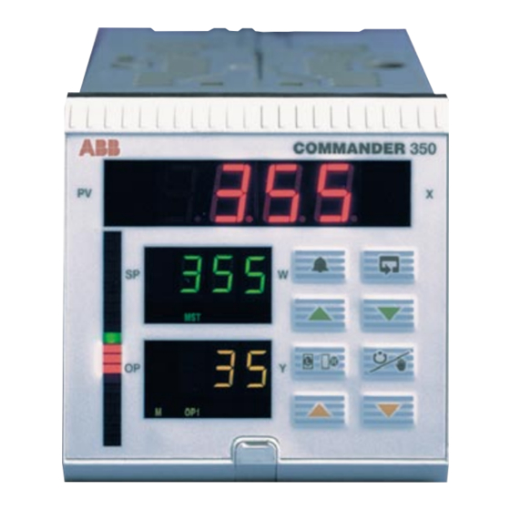
COMMANDER 351
Process Controller
3 5 1 . 0
3 5 1 . 0
MS T SLV
R
3 5
M
OP 1
OP 2 FF
User Guide
GETTING STARTED
The COMMANDER 350 can be configured and made ready for operation in three easy steps.
This 'Getting Started' guide provides an overview of these steps and, where necessary, refers to
the relevant section of the manual.
Step 1 – Decide on the Application Template and the
Output Configuration required
Step 2 – Connect the process inputs and outputs
Step 3 – Power up the instrument, set the template number and the
output configuration details
Your COMMANDER 350 is now ready for operation
Step 1 – Application Template and Output Configuration
•
Choose the Template which best suits your application from the list in Table A, located on the
rear fold-out.
•
Choose the Control Output Type required from the list of options in Table B on the rear
foldout.
Step 2 – Electrical Connections
Using the labels on the back of the instrument as a guide, connect the process inputs, outputs
and power supplies. Refer to Section 5.2 of this manual (Electrical Installation) for more
information.
Continued...
Advertisement
Table of Contents

Related Manuals for ABB COMMANDER 351


Summary of Contents for ABB COMMANDER 351
- Page 1 GETTING STARTED COMMANDER 351 User Guide Process Controller The COMMANDER 350 can be configured and made ready for operation in three easy steps. This 'Getting Started' guide provides an overview of these steps and, where necessary, refers to the relevant section of the manual.
- Page 2 Set the appropriate application template, output type and control action. Use the key to As a part of ABB, a world leader in process automation technology, we Cert. No. Q 05907 advance between frames and upper keys to adjust the default values –...
-
Page 3: Shown In Fig
OVERVIEW This manual is divided into 5 sections which contain all the information needed to install, configure, commission and operate the COMMANDER 351. Each section is identified clearly by a symbol as shown in Fig. 1. Displays and Controls Configuration Mode (Levels 6 to E) •... -
Page 4: Table Of Contents
CONTENTS Section Page Section Page DISPLAYS AND FUNCTION KEYS ..3 INSTALLATION ........71 Introduction ........3 Mechanical Installation ....71 Use of Function Keys ....... 4 Electrical Installation ...... 75 Secret-til-Lit Indicators ..... 8 Relays ..........78 Character Set ........8 Digital Output ......... -
Page 5: Displays And Function Keys
1 DISPLAYS AND FUNCTION KEYS 1.1 Introduction The COMMANDER 351 front panel displays, function keys and l.e.d. indicators are shown in Fig. 1.1. COMMANDER 350 351. 0 351. 0 Function Keys Alarm Parameter Acknowledge Advance Raise Lower Local/Remote Auto/manual Down... - Page 6 …1 DISPLAYS AND FUNCTION KEYS 1.2 Use of Function Keys A – Raise and Lower Keys LEV2 bIAS tUNE 50. 0 51. 0 LEV1 OPEr – 49. 0 Use to change/set a parameter value… and… …move between levels B – Up and Down Keys LEV2 Frame 1 2.
-
Page 7: Use Of Function Keys
1 DISPLAYS AND FUNCTION KEYS… …1.2 Use of Function Keys E – Alarm Acknowledgement (Flashing) (On continuously) (Off) 351. 5 350. 0 All active No active Any active, alarms acknowledged alarms present unacknowledged alarms 1. H P1 1HP1 2. x xx 200. - Page 8 …1 DISPLAYS AND FUNCTION KEYS …1.2 Use of Function Keys F – Local / Remote Key Changing between Local and Remote Set Points 450. 2 450. 2 450. 2 350. 0 400. 0 400. 0 Process variable and local set point displayed on red and green displays. Remote set point value is displayed.
- Page 9 1 DISPLAYS AND FUNCTION KEYS… …1.2 Use of Function Keys G – Short-cut Keys Press simultaneously and hold for 3 seconds LEVA LEV6 CntL APPL LEV1 351. 5 OPEr 350. 0 Press to move from anywhere in Press to move from the Configuration level to the first anywhere in the frame in the Operator level...
-
Page 10: Secret-Til-Lit Indicators
…1 DISPLAYS AND FUNCTION KEYS 1.3 Secret-til-Lit Indicators Flashing 350. 0 One or more No alarms active All active alarms alarms active and acknowledged unacknowledged Local set point Remote or in use Cascade set point in use 351. 5 A – Upper Display 350. -
Page 11: Error Messages
1 DISPLAYS AND FUNCTION KEYS… 1.5 Error Messages To clear the display: Error/Action Display Press the Calibration Error 351. 5 350. 0 Turn mains power off and on again (if the error persists contact the Customer Support Organization). Press the Non-volatile Memory Error 351. -
Page 12: Processor Watchdog
…1 DISPLAYS AND FUNCTION KEYS 1.6 Processor Watchdog The instrument's processor activity is monitored by an independent watchdog device. When the output of the watchdog is assigned to a relay or digital output, the relay/digital output de-energizes if the instrument fails to function correctly. 1.7 Loop Break Monitor Analog output 1 is monitored continuously to detect a loop break. -
Page 13: Operator Level
2 OPERATOR LEVEL 2.1 Introduction The Operator level (Level 1) is the normal day-to-day mode of the COMMANDER 351. This section describes the operator facilities available on each frame depending on the control template and output type selected. The template types detailed in this section are: •... - Page 14 …2 OPERATOR LEVEL 2.2 Single Loop Controller (Templates 1 and 2) The single loop controller is a basic feedback control system using three-term PID or on/off control with either a local set point (template 1) or remote set point (template 2). Local Set Point LSPt RSPt...
-
Page 15: Single Loop Controller
2 OPERATOR LEVEL… …2.2 Single Loop Controller (Templates 1 and 2) •1 Process Variable 351. 5 Control Set Point 350. 0 PV – CSPt ['SPLO' to 'SPHI' – see Section 4.5] Deviation Adjustable in Local Control Only Control Output [0 to 100% (digital/relay outputs), –10 to 110% (analog outputs)] Adjustable in manual mode only. - Page 16 …2 OPERATOR LEVEL 2.3 Auto/Manual Station (Templates 3 and 4) Note. Refer also to Appendix A2.1 – Series and Parallel Operation. The auto/manual station provides a backup for a master controller. In normal operation the COMMANDER 350’s analog output follows the master controller’s output value. A fault in the master system can be identified either by detecting a low signal on the master output (template 3) or via a digital signal (template 4).
-
Page 17: Auto/Manual Station (Templates 3 And 4)
2 OPERATOR LEVEL… …2.3 Auto/Manual Station (Templates 3 and 4) Auto Mode 55. 0 Process Variable 50. 0 Master Output (I/P2) Control Output = Master Output [Master Output, 0 to 100%] •1 •1 Restored •2 Low Master •2 Master Output Output Value •3 Digital Input... - Page 18 …2 OPERATOR LEVEL 2.4 Analog Backup (Templates 5 and 6) Note. Refer also to Appendix A2.1 – Series and Parallel Operation. The analog backup station provides a backup for a master controller. In normal operation (remote control mode selected) the COMMANDER 350’s current output follows the master controller’s output value.
-
Page 19: Analog Backup (Templates 5 And 6)
2 OPERATOR LEVEL… …2.4 Analog Backup (Templates 5 and 6) Remote Mode •1 351. 5 Process Variable 350. 0 PV – CSPt Deviation Set Point ['SPLO' to 'SPHI' – see Section 4.5] Control Output = Master Output [Master Output, 0 to 100%] Low Master •1 Restored... -
Page 20: Indicator/Manual Loader Station (Templates 7 And 8)
…2 OPERATOR LEVEL 2.5 Indicator/Manual Loader Station (Templates 7 and 8) One or two process variables can be displayed on the digital and bargraph displays. If the control output is assigned to an analog output, the lower display indicates its value which can be adjusted by the user. -
Page 21: Heat/Cool Output Types
2 OPERATOR LEVEL… 2.6 Heat/Cool Output Types 2.6.1 Reverse (Heat)/Direct (Cool) or Direct (Heat)/Reverse (Cool) The active output, either OP1 (Heat) or OP2 (Cool) is displayed and may be adjusted in manual mode. The OP1 and OP2 l.e.d.s indicate which output is changing. +100% –100% OP1 (heat) -
Page 22: Motorized Valve Output Types
…2 OPERATOR LEVEL 2.6.2 Reverse (Heat)/Reverse (Cool) or Direct (Heat)/Direct (Cool) It is not possible to view or adjust the heat/cool outputs directly. The PID output (0 to 100%), used to calculate the heat (OP1) and cool (OP2) outputs, is displayed and may be adjusted in manual mode. The OP1 and OP2 l.e.d.s indicate which output is changing. -
Page 23: Auto-Tune
2 OPERATOR LEVEL… 2.8 Auto-tune Note. Auto-tune is not available for Auto/Manual Station or Indicator templates, or when boundless or heat/cool control types are selected. Information. • Auto-tune optimizes process control by manipulating the COMMANDER 350 output and then monitoring the process response. •... - Page 24 …2 OPERATOR LEVEL 2.8.2 'At Set Point' Auto-tune If the process variable is within 10% of the set point, 'at set point' tuning is carried out. • 'At set point' tuning – manipulates the control output to produce a controlled oscillation of the process.
- Page 25 2 OPERATOR LEVEL… 2.8.3 Auto-tune Accessing the Auto-tune Facility 1. . x x xxxx From any operating frame, press and hold the key until the xxxx ' frame is displayed. COdE 1. x x COdE Set the correct auto-tune password. Auto-tune Enable 1.
- Page 26 …2 OPERATOR LEVEL 2.9 Control Efficiency Monitor The Control Efficiency Monitor can be used either to compare the relative performance with different tuning parameters, or when fine tuning the PID settings, to give optimum control. When the set point is changed, auto mode is selected or following a power failure, input failure or a large load disturbance, the control monitor performs a series of measurements to indicate the effectiveness of the current control parameters.
-
Page 27: Control Efficiency Monitor
2 OPERATOR LEVEL… …2.9 Control Efficiency Monitor period Set Point –2% approach settle Start of Calculation Fig. 2.9 Control Efficiency Monitor Parameters 2.9.1 Manual Tuning The Control Efficiency Monitor may be used for manually tuning the PID parameters. The following method describes how to tune the controller for wave damping: a) Set the integral and derivative action times to OFF. - Page 28 …2 OPERATOR LEVEL 2.9.2 Using the Control Efficiency Monitor 351. 5 Press and hold the keys for 2 seconds. 350. 0 Note. If the front panel keys are not operated for 60 seconds whilst any Control Efficiency Monitor frame is being displayed, the instrument reverts to the first operating frame.
-
Page 29: Introduction
3 SET UP MODE 3.1 Introduction To access the Set Up mode (Levels 2 to 5) the correct password must be entered in the security code frame. Press and hold 351. 5 LEV1 COdE AtNE 350. 0 OPEr Invalid password Valid Set Up or 351. -
Page 30: Level 2 – Tune
…3 SET UP MODE 3.2 Level 2 – Tune 2.00...2.04 Note. Level 2 is not applicable if an Auto/Manual Station or Indicator template is selected. Level 2 – Tune 2. 0 0 LEV. 2 tUNE Note. To select this frame from anywhere in this page, press and hold the key for a few seconds. - Page 31 3 SET UP MODE… …3.2 Level 2 – Tune 2.05...2.13 •1 Proportional Band 1 2. 0 5 Pb-1 100. 0 Enter the value for Proportional Band 1. [0.1% to 999.9%] ' is the default proportional band Pb-1 •1 Proportional Band 2, 3 and 4 2.
- Page 32 …3 SET UP MODE …3.2 Level 2 – Tune 2.13...2.21 •1 Approach Band 1 2. 1 5 Ab. 1 1. 0 [0.1 to 3.0 proportional bands] This parameter limits when derivative action time 1 is applied. When the process variable is outside the approach band, derivative action is not applied.
- Page 33 3 SET UP MODE… …3.2 Level 2 – Tune 2.22...2.23 •1 Heat/Cool Output 1 Start 2. . . 2 2 Y1. S t This parameter defines the PID output value above which 50. 0 Output 1 (heat) becomes active. [0.0 to 100.0%] Reverse-direct Reverse-reverse or direct-reverse...
- Page 34 …3 SET UP MODE 3.3 Level 3 – Set Points 3.00...3.07 Note. Level 3 is not applicable if Auto/Manual Station or Indicator templates are selected. Level 3 – Set Points 3. 0 0 LEV. 3 SEtP Note. To select this frame from anywhere in this page, press and hold the key for a few seconds.
-
Page 35: Level 3 - Set Points
3 SET UP MODE… …3.3 Level 3 – Set Points 3.10 Ramp Rate 3. 1 0 r. r tE [1 to 9999 engineering units per hour, or OFF] The Ramping Set Point facility can be used to prevent a large disturbance to the control output when the set point value is changed. -
Page 36: Level 4 - Alarm Trip Points
…3 SET UP MODE 3.4 Level 4 – Alarm Trip Points 4.00...4.08 Note. Level 4 is not applicable if all alarm types are set to 'None' – see Section 4.4, Alarms/ Alarm Type. Level 4 – Alarm Trip Points 4. 0 0 LEV. -
Page 37: Level 5 - Valve Setup
3 SET UP MODE… 3.5 Level 5 – Valve Setup 5.00...5.04 Note. Level 5 is applicable only for a motorized valve output type – see Section 4.2, Basic Configuration/ Output Type. Valve Output Open relay (PID O/P x V. r At Control Controller Process... - Page 38 …3 SET UP MODE 3.5.2 Valve Setup (Boundless Types) – Fig. 3.4 A ‘boundless’ process controller provides an output that is effectively the time derivative of the required regulator position, i.e. the COMMANDER 350 signals the regulator, not where to go to (position derivative), but in which direction to travel and how far to move, by a series of integral action pulses.
- Page 39 3 SET UP MODE 5.00...5.04 …3.5.2 Valve Setup – Boundless Level 5 – Valve Setup 5. 0 0 LEV. 5 U. L U. E Note. To select this frame from anywhere in this page, press and hold the key for a few seconds. 5.
-
Page 40: Configuration Mode
4 CONFIGURATION MODE 4.1 Introduction To access the Configuration mode (Levels 6 to E) the correct password must be entered in the security code frame. LEVE Note. When in the configuration Valid LEV6 Configuration mode, the green bargraph led illuminates. APPL password All relays and digital outputs are de-... - Page 41 4 CONFIGURATION MODE… 4.2 Level 6 – Basic Configuration 6.00...6.01 6. 0 0 LEV. 6 Level 6 – Basic Configuration APPL 6. . 0 1 t. A PP Template Application Templates are provided to make the basic configuration for a particular 1.
-
Page 42: Level 6 - Basic Configuration
…4 CONFIGURATION MODE …4.2 Level 6 – Basic Configuration 6.02 •1 6. 0 2 Control Output Type O. t YP The appropriate relays, digital outputs and analog outputs are assigned AnLG to the control output variables. The other hardware outputs are provisionally assigned to alarm and retransmission functions but these may be changed in the output assignment level –... - Page 43 4 CONFIGURATION MODE… …4.2 Level 6 – Basic Configuration Output Types: Relay Output ANLG Control Process Digital Output Algorithm Analog Output A – Single Output Output Type: Open relay Control Valve Process Algorithm Controller Close relay Position Feedback B – Motorized Valve Output with Feedback Output Type: Open relay Control...
- Page 44 …4 CONFIGURATION MODE …4.2 Level 6 – Basic Configuration 6.03...6.06 •1 Control Action 6. 0 3 C. A Ct 2 • 2 • 3 • 3 • 3 • 3 • 6. 0 6 Mains Rejection Frequency F. r EJ Used to filter mains frequency pick-up on external analog input wiring.
- Page 45 4 CONFIGURATION MODE… 4.3 Level 7 – Analog Inputs 7.00...7.03 7. 0 0 Level 7 – Analog Inputs LEV. 7 InPt Note 1. Refer also to Rear Foldout/Table A, Template Applications. Note 2. To select this frame from anywhere in this page, press the key for a few seconds.
- Page 46 …4 CONFIGURATION MODE … 4.3 Level 7 – Analog Inputs 7.04...7.07 Engineering High (I/P1) 7. 0 4 En1. H 1000 [–999 to 9999] Note. This parameter defaults to the maximum allowed value when THC or RTD inputs are selected – see Table 4.1. °C °F –...
- Page 47 4 CONFIGURATION MODE… … 4.3 Level 7 – Analog Inputs 7.08...7.14 •1 Analog Input Type & Electrical Range (I/P2) 7. 0 8 tYP2 Note. THC inputs can only be used on I/P2 if I/P1 is also set to THC. n i l •2 Temperature Units (I/P2) 7.
-
Page 48: Level 7 - Analog Inputs
…4 CONFIGURATION MODE … 4.3 Level 7 – Analog Inputs 7.15...7.21 •1 Analog Input Type & Electrical Range (I/P3) 7. 1 5 tYP. 3 n i l •2 Temperature Units 7. . 1 6 UNt3 – THC readings displayed in °C –... - Page 49 4 CONFIGURATION MODE… 4.4 Level 8 – Alarms Note. Any type of alarm can be used to sound an annunciator (klaxon/horn) which is disabled when the alarm is acknowledged. This is achieved by assigning the relay to the acknowledge state of the alarm instead of the actual alarm state.
-
Page 50: Level 8 - Alarms
…4 CONFIGURATION MODE …4.4 Level 8 – Alarms Hysteresis Trip Point Hysteresis Process Variable Alarm On High Process Alarm Off Alarm On Low Process Alarm Off Fig 4.5 High and Low Process Alarm Action Trip Point Hysteresis Process Variable Alarm On Alarm Latched Alarm Off Alarm acknowledged... - Page 51 4 CONFIGURATION MODE… …4.4 Level 8 – Alarms 8.00...8.03 8. 0 0 Level 8 – Alarms LEV. 8 ALMS Note. To select this frame from anywhere in this page, press the key for a few seconds. 8. 0 1 Alarm 1 Type tYP.
- Page 52 …4 CONFIGURATION MODE … 4.4 Level 8 – Alarms 8.04...8.25 Alarm Type 2 (Alarms 2 to 8 ) 8. 0 4 tYPx NONE 8. 0 7 [see Alarm 1 Type] 8. 1 0 8. 1 3 8. 1 6 8. 1 9 8.
- Page 53 4 CONFIGURATION MODE… 4.5 Level 9 – Set Point Configuration 9.00...9.03 Note. Level 9 is not applicable when an Indicator template (templates 7 and 8) or an Auto/Manual station template (templates 3 and 4) is selected. 9. 0 0 Level 9 – Set Point Configuration LEV9 SEt.
-
Page 54: Level 9 - Set Point Configuration
…4 CONFIGURATION MODE …4.5 Level 9 – Set Point Configuration 9.06...9.11 •1 9. . 0 6 SP. F A Remote Set Point Fault Action The action required when a fault occurs with the remote set point. NONE NONE – No action –... - Page 55 4 CONFIGURATION MODE… …4.5 Level 9 – Set Point Configuration 9.12...9.14 •1 Local/Remote Set Point Selection Source 9. 1 2 Lr. 5 r The source required to lock into remote set point mode. NONE When the source is active the key does not operate.
- Page 56 …4 CONFIGURATION MODE 4.6 Level A – Control Configuration A.00...A.02 Note. Level A is not displayed if an indicator template is selected. Level A – Control Configuration A. 0 0 LEVA CntL Note. To select this frame from anywhere in this page, press and hold the key for a few seconds.
- Page 57 4 CONFIGURATION MODE… …4.6 Level A – Control Configuration A.03...A.08 Process Variable Fail Action A. 0 3 PVFA Determines controller output when the process variable input fails. NONE – No action NONE – Put into Manual mode HOLd – Put into Manual mode and select default output dFLt Default Output A.
-
Page 58: Level A - Control Configuration
…4 CONFIGURATION MODE …4.6 Level A – Control Configuration A.09...A.12 •1 Output 2 (Cool) Low Limit – Heat/Cool Control A. 0 9 OP2L Limits the low level of control output 2 in automatic mode, when 'reverse- reverse' or 'direct-direct' control action is selected in the Basic Configuration level. - Page 59 4 CONFIGURATION MODE… …4.6 Level A – Control Configuration A.13...A.17 A. 1 3 C. O P1 Configured Output 1 The control output value required when manual is selected by manual 0. 0 mode source 1. [0 to 100% or LAST (non-heat/cool)] [–100 to 100% (heat/cool only)] A.
- Page 60 …4 CONFIGURATION MODE …4.6 Level A – Control Configuration A.18...A.22 A. 1 8 Auto Mode Selection Source A. 5 rC Select the digital source used to activate auto mode. Auto •1 See Rear Fold-out/ Table C – Digital Sources. Manual •2 A.
- Page 61 4 CONFIGURATION MODE… 4.7 Level B – Operator Configuration b.00...b.06 b. 0 0 LEVb Level B – Operator Configuration OPEr Note. To select this frame from anywhere in this page, press and hold the key for a few seconds. •1 b.
-
Page 62: Level B - Operator Configuration
…4 CONFIGURATION MODE …4.7 Level B – Operator Configuration b.07...b.16 •1 b. 0 7 A. P A5 Auto-tune Password Enables access to the auto-tune facility in the operator level. [0 to 9999 (default 0)] b. 1 0 S. P AS Set Up Password Enables access to the set up levels (levels 2, 3, 4 and 5) and the autotune facility. -
Page 63: Level C - Output Assignment Configuration
4 CONFIGURATION MODE… 4.8 Level C – Output Assignment Configuration C.00, C01 Note. The Output Assignment default settings are preconfigured to each template – see Table B, Output Sources on the rear fold-out. Level C – Output Assignment C. 0 0 LEV. - Page 64 …4 CONFIGURATION MODE 4.8.1 Digital Output 1 C07, C08 tYP1 •1 Digital Output 1 (do1) Assignment Source C. 0 7 dGI. A Select the source required to activate Digital Output 1. NONE See Rear Fold-out/ Table C – Digital Sources. Digital Output 1 (do1) Polarity •2 The output can be set to energize for either an active or inactive digital...
- Page 65 4 CONFIGURATION MODE… 4.8.2 Analog Output 1 C02...C06 tYP1 ANLG •1 C. 0 2 Analog Output 1 (ao1) Assignment Source AnI. A Select the source required to activate Analog Output 1. NONE See Rear Fold-out/ Table D – Analog Sources. C.
- Page 66 …4 CONFIGURATION MODE 4.8.3 Analog Output 2 C10...C14 dG1. P 0. 0 0. 0 •1 Analog Output 2 (ao2) Assignment Source C. 1 0 AN2. A Select the source required to activate Analog Output 2. NONE See Rear Fold-out/ Table D – Analog Sources. •1 Analog Output 2 (ao2) Electrical High C.
- Page 67 4 CONFIGURATION MODE… 4.8.4 Relay Outputs 1 to 4 C17...C22 0. 0 0. 0 •1 C. . 1 7 rL1. A Relay 1 Assignment Source Select the source required to activate relay output 1. NONE See Rear Fold-out/ Table C – Digital Sources. •2 C.
- Page 68 …4 CONFIGURATION MODE …4.8.4 Relay Outputs 1 to 4 C23...C24 •1 C. . 2 3 Relay 4 Assignment Source rL4. A •4 Select the source required to activate relay output 4. NONE See Rear Fold-out/ Table C – Digital Sources. •2 C.
-
Page 69: Level D - Serial Communications Configuration
4 CONFIGURATION MODE… 4.9 Level D – Serial Communications Configuration d.00...d.03 Note. Level D is only applicable if the serial communications option is fitted. d. 0 0 LEVd Level D – Serial Communications Configuration SErL Note. To select this frame from anywhere in this page, press and hold the key for a few seconds. - Page 70 …4 CONFIGURATION MODE 4.10 Level E – Calibration E.00...E.04 Note. This page enables fine tuning of the inputs to eliminate system errors. Level E – Calibration E. 0 0 LEVE Note. To select this frame from anywhere in this page, press the key for a few seconds.
- Page 71 4 CONFIGURATION MODE… …4.10 Level E – Calibration E.05...E.10 E. 0 5 OFF. 3 Analog Input 3 Offset Calibration Analog Input 3 Value in Engineering Units 100. 3 8888 0. 0 Offset [In engineering Units] If the keys are not operated for three seconds the display reverts to the offset value only.
-
Page 72: Level E - Calibration
…4 CONFIGURATION MODE …4.10 Level E – Calibration E.11...E.16 FCAL •1 Fb. L O Position Feedback Electrical Range Low Set the minimum electrical input value. 100. 0 [0.0 to 999.9] For resistance input types, no decimal places are displayed. For all other input types, 1 decimal place is displayed. -
Page 73: Installation
5 INSTALLATION EC Directive 89/336/EEC In order to meet the requirements of the EC 55°C Directive 89/336/EEC for EMC regulations, this Max. product must not be used in a non-industrial environment. 0°C Min. Cleaning A – Within Temperature Limits Clean only the front panel, using warm water and a mild detergent. - Page 74 …5 INSTALLATION 5.1.2 Mounting – Figs. 5.3 to 5.5 The instrument is designed for panel mounting (Fig. 5.4). Overall dimensions are shown in Fig. 5.3. Note. For NEMA4X protection, a minimum panel thickness of 2.5mm is recommended. Dimensions in mm (in.) 17.5 (0.69) 122.5 (4.82)
- Page 75 5 INSTALLATION… …5.1.2 Mounting – Figs. 5.3 to 5.5 Cut a hole in the panel (see Fig. 6.3 for dimensions). Instruments may be close stacked to DIN 43835 Insert the instrument into the panel cut-out Ground studs Fit the panel clamps, ensuring that the lugs are located correctly in their slots Secure the panel clamp using the retaining screws.
- Page 76 …5 INSTALLATION …5.1.2 Mounting – Figs. 5.3 to 5.5 Release the jacking screw cover Turn the jacking screw anticlockwise to pull the instrument from the case Note. Refitting is the reversal of removal. Fig. 5.5 Inserting/Removing the Instrument from the Case...
-
Page 77: Electrical Installation
Terminals for external circuits are for use only with equipment with no accessible live parts. Caution. • If the COMMANDER 351 is used in a manner not specified by the Company, the protection provided by the equipment may be impaired. •... - Page 78 …5 INSTALLATION 5.2.1 Electrical Connections – Figs 5.6 to 5.8 Output/ Digital / Analog Output 1 Power Supply Terminals (ao1 /do1) – Analog Output 2 (ao2) – Terminal blocks viewed from rear of Relay 1 case (RLY1) Caution. The AC power supply ground cable must be connected to a Relay 2...
- Page 79 5 INSTALLATION… …5.2.1 Electrical Connections – Figs 5.6 to 5.8 milliamps voltage 3-lead 2-lead RTD * milliamps millivolts and Resistance and volts lead – RTD – – **100Ω **100Ω Analog RTD – RTD – Input 1 (I/P 1) CJ Sensor# –...
-
Page 80: Relays
…5 INSTALLATION 5.3 Relays 5.4 Digital Output 15 V DC min. at 20 mA Min. load 750 Ω Note. Refer Rear Fold-out/ Table B for default relay assignments. Relay contacts are rated at: 5.5 Control or Retransmission 115/230 V AC at 5 A (non-inductive) Analog Output 250 V DC 25 W max. -
Page 81: Motorized Valve
5 INSTALLATION… 5.6 Motorized Valve 5.7 Input Connections Connections – Fig. 5.10 Make connections to each input – see Fig 5.7. Refer to Table A on the rear fold-out for the Note. Relays used to drive the motorized default input assignment settings. valve must be set for 'Normally Open' operation –... -
Page 82: Output Connections
…5 INSTALLATION 5.7.2 3-lead Resistance 5.8 Output Connections Thermometer (RTD) Inputs Make connections as shown in Fig 5.6. The three leads must have equal resistance, not Refer to Table B on the rear fold-out for the exceeding 50Ω each. default output assignment settings. 5.7.3 2-lead Resistance 5.9 Power Supply Connections Thermometer (RTD) Inputs... -
Page 83: Appendix A - Control Templates
APPENDIX A – CONTROL TEMPLATES A1 Single Loop Controller (Templates 1 and 2) -
Page 84: A2 Auto/Manual Station And Analog Backup Station
…APPENDIX A – CONTROL TEMPLATES A2 Auto/Manual Station and Analog Backup Station A2.1 Series and Parallel Operation Note. See Sections A2.2 and A2.3 for detailed templates. C350 Process Process Variable I/P1 Master Output Actuator I/P2 Output Master Controller Digital Select Status di.1 Series Connection... - Page 85 APPENDIX A – CONTROL TEMPLATES… …A2.2 Auto/Manual Station (Templates 3 and 4)
- Page 86 …APPENDIX A – CONTROL TEMPLATES A2.3 Analog Backup (Templates 5 and 6)
-
Page 87: A3 Indicator/Manual Loader Station (Templates 7 And 8)
APPENDIX A – CONTROL TEMPLATES A3 Indicator/Manual Loader Station (Templates 7 and 8) -
Page 88: Appendix B - Commander Configuration Editor
APPENDIX B – COMMANDER CONFIGURATION EDITOR B1 Introduction Using the COMMANDER Configurator the COMMANDER 350 can be programmed without using any of the front panel keys. In addition to the standard settings, the Configurator also gives access to more advanced features not accessible via the front panel keys. -
Page 89: B7 Two Delay Timers
APPENDIX B – COMMANDER CONFIGURATION EDITOR B7 Two Delay Timers • Programmable delay and duration (0 to 9999 seconds) B8 Two Custom Linearizers • 15 breakpoints per linearizer • The source can be any analog signal B9 Template Customization Each template can be customized by changing the sources for various functions in the COMMANDER 350. -
Page 90: Specification
SPECIFICATION Standard Functions Summary Control Strategies • 8 application templates: Single loop, Auto/Manual, Single-loop, Auto/manual Station, Analog Backup, Analog backup, Indicator Indicator/Manual Loader • Two Autotune options Output Types Current proportioning, Time proportioning, On/off, • Control Efficiency Monitor (CEM) Motorized valve (with and without feedback), Heat/cool. •... - Page 91 SPECIFICATION... Analog Inputs Analog Inputs – Common Linearizer Functions Universal Process Inputs THC types B, E, J, K, L, N, R, S, T, PT100, √, Number Input Impedance 2 standard 100Ω Type mV, V 10MΩ Universally configurable to provide: Broken Sensor Protection Thermocouple (THC) Programmable for upscale or downscale drive Resistance thermometer (RTD)
- Page 92 ...SPECIFICATION Outputs Options Control/Retransmission Outputs Relay Outputs Number 2 standard Number Type 1 x programmable as analog or logic (digital) Type SPST, rated 5A at 115/230V AC output Digital Inputs 1 x analog only Number Isolation Galvanically isolated from the rest of the Type Volt-free circuitry...
- Page 93 SPECIFICATION Physical Environmental Size Operating Limits 96 x 96 x 122.5mm (3.78 in. x 3.78 in. x 4.82 in.) 0°C to 55°C (32°F to 130°F) 5 to 95%RH (non-condensing) Weight 680g (1.5lb) Temperature stability <0.02%/°C or 2µV/°C (<0.011%/°F or 1.11µV/°F) Electrical Long term drift <0.02% of reading or 20µV annually Voltage...
-
Page 94: Frames Index
FRAMES INDEX Set Up Frames Frame Title Mnemonic Number Frame Title Mnemonic Number Proportional Band 1 Alarm 1 Trip Pb-1 2. 0 5 1. x xx 4. 0 1 Proportional Band 2 Pb-2 2. 0 6 Alarm 2 Trip 2. x xx 4. - Page 95 FRAMES INDEX… Configuration Frames Frame Title Frame Title Mnemonic Number Mnemonic Number Basic Configuration Alarm 1 Hysteresis HYS. 1 8. 0 3 LEV6, APPL 6. 0 0 Bias Display Enable Alarm 1 Trip trP. 1 8. 0 2 b. d IS b.
- Page 96 …FRAMES INDEX …Configuration Frames Frame Title Frame Title Mnemonic Number Mnemonic Number Power Fail Recovery Mode Input 1 Broken Sensor bSd. 1 7. 0 6 P. r EC A. 0 1 Power Fail Recovery Time Input 1 Decimal Point dP. 1 7.
-
Page 97: Index
INDEX …C Accessories .............. 1 Configuration Error ........... 9 Alarms ............34, 47 Configuration Password ......... 60 Acknowledge ..........5, 50 Configured Outputs 1 to 3 ........57 Acknowledge enable ........59 See Also: Auto/Manual and Backup Templates Configuration ........... 47 Control Action ............ - Page 98 …INDEX …O Heat/Cool ..............19 Output Control Action ........... 40, 42 Assignment – Level C ........61 Output limits ............ 55 Connections ........76, 78, 79 Start positions ..........31 Heat/Cool ............19 Hysteresis Limits ............... 55 Alarms ............ 47 to 50 Slew Rate ............
- Page 99 INDEX Secret-til-Lit Indicators ..........8 Security Options ............. 60 Serial Communications – Level d ......67 Set Points Configuration – Level 9 ........51 Default Value ........... 52 Limits ............... 51 Operator Adjust enable ........59 Ramp Rate ............33 Scaling .............
- Page 100 NOTES...
- Page 101 NOTES...
- Page 102 ...NOTES...
- Page 103 – Food & Beverage † – Manufacturing . 2 L United Kingdom † – Metals and Minerals ABB Limited . 3 M – – Oil, Gas & Petrochemical Tel: +44 (0)1480 475321 – Pulp and Paper . 4 M i g i –...
- Page 104 – r i f – – Table D – Analog Sources ABB has Sales & Customer The Company's policy is one of continuous Support expertise in over 100 product improvement and the right is countries worldwide reserved to modify the information contained herein without notice.