Advertisement
Quick Links
Advertisement

Related Manuals for Anet A6


Summary of Contents for Anet A6
- Page 1 A6 3D Printer Installation Instruction...
- Page 2 Introduction Attention: 1.Please make sure the package not broken when you receive it. 2.Please check the printer parts according to the packing list. 3. Please contract your supplier if any questions.
-
Page 3: Tool List
Tool List... - Page 7 Please check printer parts quantity when you receive it .
-
Page 8: Components Name
Components Name... - Page 9 Acrylic Installation Acrylic Connection Acrylic & Motor Connection Acrylic Connection...
- Page 10 Mainboard Installation Name Note Main Support Plate Left&Right Support Plate M3*18mm Screw M3 Nut Mainborad Left&Right Support Plate Please pay attention to the direction of main support plate...
- Page 11 Left&Right Locking Board Installation Right Locking Left Locking Board Name Note Board Left Locking Board Right Locking Board M3*18 Screw M3 Nut Please pay attention to the direction of Left&Right board...
- Page 12 Back Fixing Plate Installation Name QTY Note Name Note Y Limited Y Limited Swtich Back Fixing Plate Switch Fixing Plate Back Fixing Plate Y Motor Fixing M2 Screw Plate Y Limited Switch Y Motor Support M3*18 Screw Y Motor Support Y Limited Swtich M3 Nut Y Motor Fixing Plate...
- Page 13 Back Fixing Plate Installation Name Note M3*18 Screw M3 Nut...
- Page 14 Front Fixing Plate Installation Name Note Front Fixing Plate Y Belt Bearing Support M3*18 Screw Front Fixing Plate Y Belt Bearing Support M3Nut Attention: The belt bearing up...
- Page 15 Front Fixing Plate Installation Name Note M8*400 Threaded Rod M8 Nut Screw nut&Spacer Installation M8 Spacer...
- Page 16 Y Leading Rod Installation Name Note Linear Slide 8*380mm Leading Rod Linear Slide 8*380mm Leading Rod Leading Rod Bracket M3*18 Screw M3 Nut Leading Rod Bracket...
- Page 17 Hotbed Fixing Plate Installation Name Note Y Belt Fixing Clip Hotbed Fixing Plate M4*14 Screw Y Belt Fixing Clip Hotbed Fixing Plate Attention : Leave some gap for screw for belt installation...
- Page 18 Hotbed Fixing Plate Installation Name Note M4*8 Screw Y Belt Bearing Fixate one end of the belt on , pass belt through Y motor syn chronous wheel , through Y belt bearing and fixate on (Meanwhile tension belt) Y motor synchronous wheel...
- Page 19 Hotbed Installation Name Note 220mm*220mm*3mm Aluminum Hotbed M3*30 Screw Spring Butterfly Nut Spring Aluminum Hotbed Butterfly Nut...
- Page 20 The connection head should go The gap between hotbed&hotbed towards Y motor direction fixing plate screw is about 3mm...
- Page 21 Z Motor Installation Name Note Name Note Left&Right Z Motor M3*18 Screw Fixing Plate Z Motor Support M3 Nut Z Motor M3*12 Screw The Small hole should face outward...
- Page 22 Left Z Threaded Rod Screw Nut Support Installation Name Note Left Z Threaded Rod Screw Nut Support X Motor M3*12 Screw...
- Page 23 Left Z Threaded Rod Screw Nut Support Installation Name QTY Note Left Z Threaded Rod Screw Nut Support & X Leading Rod Bracket motor Right Z Threaded Rod Screw Nut Support Right Z Threaded Rod 8*340mm Leading Rod Left Z Threaded Rod Screw Screw Nut Support Nut Support &...
- Page 24 T Threaded Rod Installation Name Note Threaded Rod M8*318mm Threaded Rod M8*318mm Loose set screw , install threaded rod and then tighnen it . Threaded Rod Installation...
- Page 25 X Leading Rod Installation Name Note 8*422mm Leading 8*422mm Leading Rod Extruder Extruder Loose M3 screw to install leading rod...
- Page 26 X Leading Rod Bracket Installation Position Note Tighten the screw in white circle Pay attention to the bracket , fixate bracket when it turns to picture 2 Picture 2...
- Page 27 X Limited Switch Support & Blower Installation Name Note X Limited Switch Support Blower Support M3*10 Screw M3*6 Screw...
- Page 28 Blower & Limited Switch Installation Name Note X Limited Switch Wind Mouth Blower X Limited Switch M3*25 Screw Blower M3 Nut Wind Mouth M2 Self-tapping Screws...
- Page 29 Fixate belt in , Pass belt through X motor Synchronous wheel and belt bearing , then pass , tension belt and lock...
- Page 30 LCD Screen Installation Name Note 12864 LCD Screen Screen Protection M3*7 Pillar Board 12864 LCD Screen M3*7 Pillar M3 Screw Nut M3*30 Screw M3 Nut M3*30 Screw Screen Protection Board Screw Nut Screw Nut Screw & Pillar Position Pillar...
- Page 31 Mainboard Installation Name Note Mainboard M3*15 Pillar M3*25 Screw M3 Nut Mainboard Please install mainboard aside of Please Install in the recommended hole the left Z threaded rod support...
- Page 32 Power Supply Installation Attention This is the wiring diagram of power supply. 1, 2, 3 seperately represent the line of fire (brown),Zero line (blue), ground wire (yellow). 4,5, 6 represent negative pole (black) (-); 7,8,9 represent the positive pole (red) (+).To avoid danger , please assure the installation is correct .
- Page 33 Power Supply Installation Name Note Power Supply M3*12 Screw Power Supply Please Install power supply in the recommended hole...
- Page 34 Mainboard Protection Board Installation Please ensure you have Name Note connected all wires right Mainboard before mainboard protection Protection Board board installation M3*18 Screw Mainboard Protection M3 Nut Board...
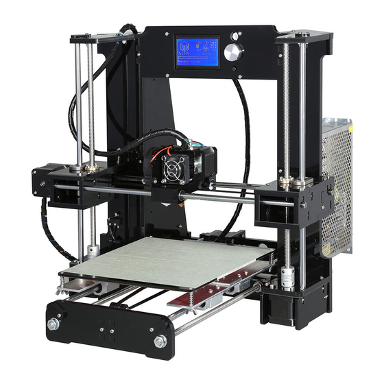
- Page 35 Finished Map...
- Page 36 Attention: Please link components with corresponding wires , especially motor wire & limited switch wire. Length of Each Wire of A6...
- Page 37 Please refer to the picture during connection. Please ensure you the connection is right!!!
- Page 38 Attention: Please connect compenents with corresponding wires...
-
Page 39: Printer Display
Printer Display... -
Page 45: Installation Complete
Installation Complete Congratulations ! You have just made yourself a 3D printer ! Please contact your 3D printer supplier if any puzzles during using process. Thank you for choosing our products, we will always provide you more services.
Need help?
Do you have a question about the A6 and is the answer not in the manual?
Questions and answers