Advertisement
Advertisement
Table of Contents

Related Manuals for Anet E10


Summary of Contents for Anet E10
- Page 1 E10-3D Printer Installation Guide...
- Page 2 E10 Installation Guide Attention: 1. Please check if the package is complete before signing for it. 2. After you unbox the product, please check if the parts are in accord with Bill of Material. 3. If there is any problem, please contact your supplier as soon as possible.
- Page 3 Precautions for sticking 3M sticker 1. 3M sticker may not be peeled off easily, please use it carefully. 2. Before sticking, please make sure there is no foreign matter or dust on the surface of hot bed. 3. When sticking, please align sticker at the hot bed.
- Page 4 E10 assembly parts list 1...
- Page 5 E10 assembly parts list 2 You can print the printed parts on E10 by yourself,the stl files are save in file Print Model STL Please check if the parts are in accord with Bill of Material!
- Page 6 Part Name...
- Page 7 Step 1 PIC 1 PIC 2 Picture 1 is the chassis, and Picture 2 is the vertical frame.
- Page 8 Step 2 Please insert the vertical frame M4*9 Screws are tightened up already correctly into the chassis...
- Page 9 Step 3 M6*20 Hexagon Socket Screw Attention: Be aware of the vertical frame is not attached to the chassis firmly at this moment, do not turn the frame around. Please mount M6*20 screws from the bottom and tighten them up Bottom...
- Page 10 Step 4 M4*10 ATTN:The red circle shows the screw hole position Before Mount M4*10 Hexagon Socket Screw...
- Page 11 Step 5 Before After After mounting, please leave the power supply box alone, you will need it when wiring.
- Page 12 Step 6 Tighten the black jackscrew up after the installation of heating tube and thermister. 1.Loose the M4*9 screws at two sides to enable “T” nut to turn to landscape and lock the Aluminum frame. 2.When there is space between screw head and Aluminum frame, the nut would trun to landscape to lock the frame automatically.
- Page 13 Step 7 M3*5 Hexagon Socket Screw Put the wires into “U” groove Mount M3*4 screws into the screw hole after the installation of fan cover.
- Page 14 Step 8 Screw on “R” clip Extruder hole Extruder motor hole 1. Please screw out the screw on “R” clip; 2. Put protective cover of wires on the fan cover into the “R” clip, and tighten the screw up. Filament tube installation: Please insert filament tube into Extruder motor hole, and then insert the tube into Extruder hole in the other end.
- Page 15 Step 9 Please connect wires according to the labels with the corresponding sockets on the printer X Axis Motor E Axis Motor (Extruder) Left Z Axis Motor Right Z Axis Motor Hotbed Y Axis Motor Y Axis Limit Switch...
- Page 16 Step 9 Fan Cover X Axis Limit Switch Z Axis Limit Switch...
- Page 17 Step 9 Z Axis Limit X Axis Limit Switch Switch Black Wire Socket Red Wire Socket...
- Page 18 Step 9 E Axis Motor X Axis Motor Left Z Axis (Extruder) Motor Hotbed Y Axis Motor Right Z Axis Please insert the hot Motor Y Axis Limit Switch bed wire tightly in case of burning out.
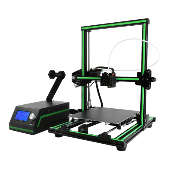
- Page 19 Step 10 Finished Product 1...
- Page 20 Step 10 Finished Product 2...
- Page 21 Step 10 Finished Product 3...
- Page 22 Finished! • Congratulations that you own a 3d printer now; • Please contact your supplier if you have any problem during application. • Thanks for choosing us, and we hope to provide more services in the future.
Need help?
Do you have a question about the E10 and is the answer not in the manual?
Questions and answers