Siemens SINAMICS G120 Operating Instructions Manual
Low voltage converters
chassis devices with cu240b-2 and cu240e-2
Hide thumbs
Also See for SINAMICS G120:
- List manual (1256 pages) ,
- Manual (732 pages) ,
- Operating instructions manual (550 pages)

Subscribe to Our Youtube Channel
Related Manuals for Siemens SINAMICS G120


Summary of Contents for Siemens SINAMICS G120
- Page 1 Operating instructions SINAMICS SINAMICS G120 Low voltage converters Chassis devices with CU240B-2 and CU240E-2 Control Units Edition 01/2017 www.siemens.com/drives...
-
Page 3: Description
Changes in the current manual Fundamental safety instructions SINAMICS Introduction Description SINAMICS G120 Converter with the CU240B-2 and Installing CU240E-2 Control Units Commissioning Operating Instructions Advanced commissioning Saving the settings and series commissioning Alarms, faults and system messages Corrective maintenance... - Page 4 Note the following: WARNING Siemens products may only be used for the applications described in the catalog and in the relevant technical documentation. If products and components from other manufacturers are used, these must be recommended or approved by Siemens. Proper transport, storage, installation, assembly, commissioning, operation and maintenance are required to ensure that the products operate safely and without any problems.
-
Page 5: Changes In The Current Manual
The following Power Modules are no longer described in the current edition of the manual: ● PM240 Power Module ● PM340 Power Module ● PM260 Power Module Additional information is provided on the Internet: PM240 Power Modules mounting instructions (https://support.industry.siemens.com/cs/ww/ en/view/109738501) Installation Guide for the PM260 Power Module (https://support.industry.siemens.com/cs/ww/ en/view/79109730) Corrections ●... - Page 6 Changes in the current manual ● After selecting the "Standard Drive Control" application class, only the settings p1900 = 0 or 2 are possible for the motor data identification. The settings p1900 = 1, 3, 11 and 12 have been removed. Standard Drive Control (Page 158) Standard Drive Control (Page 138) ●...
-
Page 7: Table Of Contents
Table of contents Changes in the current manual........................5 Fundamental safety instructions.........................15 General safety instructions.....................15 Handling electrostatic sensitive devices (ESD)..............20 Industrial security........................21 Residual risks of power drive systems...................22 Introduction..............................23 About the Manual........................23 Guide through the manual......................24 Description..............................27 Identifying the converter......................28 Directives and standards......................29 Overview of Control Units......................31 Power Module........................33 3.4.1... - Page 8 Table of contents 4.3.4 Dimension drawings, drilling dimensions for the PM230 Power Module, IP20......63 4.3.5 Dimension drawings, drilling dimensions for PM230 and PM240-2 Power Modules utilizing push-through technology...................65 4.3.6 Dimensioned drawings, drilling dimensions for the PM250 Power Module......67 Connecting the line supply, motor, and inverter components..........69 4.4.1 TN line system........................69 4.4.2...
- Page 9 Table of contents 5.4.2 Overview of quick commissioning..................135 5.4.3 Start quick commissioning and select the application class..........136 5.4.4 Standard Drive Control......................138 5.4.5 Dynamic Drive Control......................140 5.4.6 Expert...........................142 5.4.7 Identifying the motor data and optimizing the closed-loop control........147 Quick commissioning with a PC...................149 5.5.1 Creating a project.........................149 5.5.2...
- Page 10 Table of contents 6.10 Switching over the drive control (command data set)............220 6.11 Motor holding brake......................222 6.12 Free function blocks......................226 6.12.1 Overview..........................226 6.12.2 Further information.......................226 6.13 Selecting physical units......................227 6.13.1 Select the motor standard....................227 6.13.2 Selecting the system of units....................227 6.13.3 Selecting the technological unit of the technology controller..........229 6.13.4...
- Page 11 Table of contents 6.19 Electrically braking the motor....................302 6.19.1 DC braking...........................304 6.19.2 Compound braking.......................307 6.19.3 Dynamic braking........................309 6.19.4 Braking with regenerative feedback to the line..............311 6.20 Overcurrent protection......................312 6.21 Inverter protection using temperature monitoring..............313 6.22 Motor protection with temperature sensor................316 6.23 Motor protection by calculating the temperature..............319 6.24...
- Page 12 Table of contents Identification & maintenance data (I&M)................378 Alarms, alarm buffer, and alarm history................379 Faults, alarm buffer and alarm history..................382 List of alarms and faults.......................386 Corrective maintenance..........................395 Spare parts compatibility......................395 Replacing inverter components....................396 9.2.1 Overview of replacing converter components..............396 9.2.2 Replacing a Control Unit with enabled safety function............398 9.2.3 Replacing the Control Unit without the safety functions enabled.........402...
- Page 13 Table of contents 10.6.1 Ambient conditions.......................458 10.6.2 General technical data, PM230....................460 10.6.3 Detailed technical data, PM230...................461 10.6.4 Current reduction depending on pulse frequency..............466 10.7 Technical data, PM250 Power Module................467 10.7.1 High Overload - Low Overload.....................467 10.7.2 Ambient conditions.......................467 10.7.3 General technical data, PM250....................469 10.7.4 Specific technical data, PM250....................470 10.7.5...
- Page 14 Table of contents Converter with the CU240B-2 and CU240E-2 Control Units Operating Instructions, 01/2017, FW V4.7 SP6, A5E34259001B AD...
-
Page 15: Fundamental Safety Instructions
Fundamental safety instructions General safety instructions DANGER Danger to life due to live parts and other energy sources Death or serious injury can result when live parts are touched. ● Only work on electrical devices when you are qualified for this job. ●... - Page 16 Fundamental safety instructions 1.1 General safety instructions WARNING Danger to life when live parts are touched on damaged devices Improper handling of devices can cause damage. For damaged devices, hazardous voltages can be present at the enclosure or at exposed components;...
- Page 17 Fundamental safety instructions 1.1 General safety instructions NOTICE Material damage due to loose power connections Insufficient tightening torques or vibrations can result in loose electrical connections. This can result in damage due to fire, device defects or malfunctions. ● Tighten all power connections with the specified tightening torques, e.g. line supply connection, motor connection, DC link connections.
- Page 18 Fundamental safety instructions 1.1 General safety instructions WARNING Danger to life due to the motor catching fire in the event of insulation overload There is higher stress on the motor insulation through a ground fault in an IT system. If the insulation fails, it is possible that death or severe injury can occur as a result of smoke and fire.
- Page 19 Fundamental safety instructions 1.1 General safety instructions WARNING Danger to life when safety functions are inactive Safety functions that are inactive or that have not been adjusted accordingly can cause operational faults on machines that could lead to serious injury or death. ●...
-
Page 20: Handling Electrostatic Sensitive Devices (Esd)
Fundamental safety instructions 1.2 Handling electrostatic sensitive devices (ESD) Handling electrostatic sensitive devices (ESD) Electrostatic sensitive devices (ESD) are individual components, integrated circuits, modules or devices that may be damaged by either electric fields or electrostatic discharge. NOTICE Damage through electric fields or electrostatic discharge Electric fields or electrostatic discharge can cause malfunctions through damaged individual components, integrated circuits, modules or devices. -
Page 21: Industrial Security
Siemens’ products and solutions undergo continuous development to make them more secure. Siemens strongly recommends to apply product updates as soon as available and to always use the latest product versions. Use of product versions that are no longer supported, and failure to apply latest updates may increase customer’s exposure to cyber threats. -
Page 22: Residual Risks Of Power Drive Systems
Fundamental safety instructions 1.4 Residual risks of power drive systems Residual risks of power drive systems When assessing the machine- or system-related risk in accordance with the respective local regulations (e.g., EC Machinery Directive), the machine manufacturer or system installer must take into account the following residual risks emanating from the control and drive components of a drive system: 1. -
Page 23: Introduction
Introduction About the Manual Who requires the operating instructions and what for? These operating instructions primarily address fitters, commissioning engineers and machine operators. The operating instructions describe the devices and device components and enable the target groups being addressed to install, connect-up, set, and commission the converters safely and in the correct manner. -
Page 24: Guide Through The Manual
Introduction 2.2 Guide through the manual Guide through the manual Section In this section you will find answers to the following questions: Description (Page 27) ● How is the inverter marked? ● Which components make up the inverter? ● Which optional components are available for the inverter? ●... - Page 25 Introduction 2.2 Guide through the manual Section In this section you will find answers to the following questions: Technical data (Page 419) ● What is the inverter technical data? ● What do "High Overload" and "Low Overload" mean? Appendix (Page 477) ●...
- Page 26 Introduction 2.2 Guide through the manual Converter with the CU240B-2 and CU240E-2 Control Units Operating Instructions, 01/2017, FW V4.7 SP6, A5E34259001B AD...
-
Page 27: Description
You can use equivalent products from other manufacturers. Siemens does not accept any warranty for the properties of third-party products. Converter with the CU240B-2 and CU240E-2 Control Units Operating Instructions, 01/2017, FW V4.7 SP6, A5E34259001B AD... -
Page 28: Identifying The Converter
Description 3.1 Identifying the converter Identifying the converter Main components of the inverter Each SINAMICS G120 inverter comprises a Control Unit and a Power Module. ● The Control Unit controls and monitors the connected motor. ● The Power Module provides the connections for line supply and motor. -
Page 29: Directives And Standards
Description 3.2 Directives and standards Directives and standards Relevant directives and standards The following directives and standards are relevant for the inverters: European Low Voltage Directive The inverters fulfil the requirements stipulated in the Low-Voltage Directive 2014/35/EU, if they are covered by the application area of this directive. European Machinery Directive The inverters fulfil the requirements stipulated in the Machinery Directive 2006/42//EU, if they are covered by the application area of this directive. - Page 30 Description 3.2 Directives and standards Quality systems Siemens AG employs a quality management system that meets the requirements of ISO 9001 and ISO 14001. Certificates for download ● EC Declaration of Conformity: (https://support.industry.siemens.com/cs/ww/de/view/ 58275445) ● Certificates for the relevant directives, prototype test certificates, manufacturers declarations and test certificates for functions relating to functional safety ("Safety...
-
Page 31: Overview Of Control Units
Description 3.3 Overview of Control Units Overview of Control Units Table 3-1 Control Units CU240B-2 … The CU240B-2 Control Units differ with regard to the type of fieldbus. Designation CU240B-2 CU240B-2 DP Article number 6SL3244-0BB00-1BA1 6SL3244-0BB00-1PA1 Fieldbus USS, Modbus RTU PROFIBUS DP Table 3-2 Control Units CU240E-2 …... - Page 32 Description 3.3 Overview of Control Units Adapter for operating a PM230 IP55 Power Module For operating the Control Unit with a PM230 IP55 Power Module, FSA … FSC, an adapter is required between the Control Unit and operator panel (BOP‑2 or IOP). The adapter, which is included in the scope of delivery of the Power Module, is too short for the CU240E‑2 Control Unit.
-
Page 33: Power Module
Description 3.4 Power Module Power Module Important data on the Power Modules is provided in this section. Further information is contained in the Hardware Installation Manual of the Power Module. Overview of the manuals (Page 504) All power data refers to rated values or to power for operation with low overload (LO). Which Power Module can I use with the Control Unit? Table 3-4 Permitted combinations of Control Unit and Power Module... -
Page 34: Power Module With Ip20 Degree Of Protection
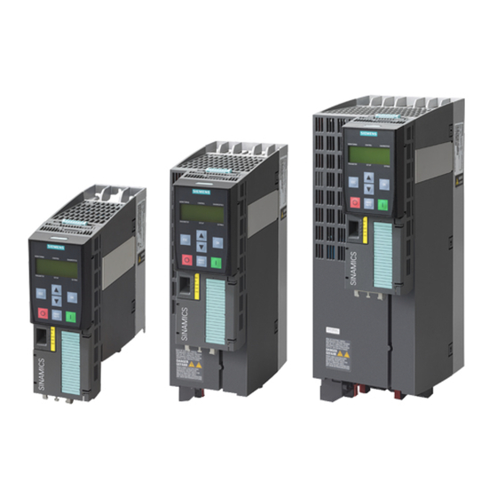
Description 3.4 Power Module 3.4.1 Power Module with IP20 degree of protection Figure 3-2 Examples of Power Modules with IP20 degree of protection PM240-2 for standard applications The PM240-2 Power Module is available without a filter or with an integrated class A line filter. The PM240-2 permits dynamic braking via an external braking resistor. - Page 35 Description 3.4 Power Module PM240P-2 for standard applications The PM240P-2 Power Module is available without a filter or with an integrated class A line filter. Table 3-8 3-phase 380 VAC … 480 VAC, article number 6SL3210-1RE… Frame size Power (kW) 22 …...
-
Page 36: Power Module With Push-Through Technology
Description 3.4 Power Module 3.4.2 Power Module with Push-Through technology Figure 3-3 Examples of Power Modules with Push-Through technology FSA … FSC PM240-2 with Push-Through technology for standard applications The PM240-2 Power Module is available with Push-Through technology without a filter or with an integrated class A line filter. -
Page 37: Power Module In Ip55 Degree Of Protection / Ul Type 12
Description 3.4 Power Module 3.4.3 Power Module in IP55 degree of protection / UL Type 12 Figure 3-4 PM230, 3-phase 400 VAC, degree of protection IP55 / UL Type 12 PM230 for pumps and fan applications The PM230 Power Module is suitable for cabinet-free installation. Table 3-15 3-phase 380 VAC …... -
Page 38: Components For The Power Modules
Description 3.5 Components for the Power Modules Components for the Power Modules 3.5.1 Accessories for shielding Shield connection kit Establish the shield and strain relief for the power connec‐ tions using the shield connection kit. The shield connection kit comprises a shield plate and serrated strips with screws. -
Page 39: Line Filter
Description 3.5 Components for the Power Modules 3.5.2 Line filter With a line filter, the inverter can achieve a higher radio interference class. An external filter is not required for inverters with integrated line filter. NOTICE The line filter is damaged when operated on inadmissible line supplies The line filter is only suitable for operation on TN or TT line supplies with a grounded neutral point. -
Page 40: Line Reactor
Description 3.5 Components for the Power Modules 3.5.3 Line reactor The line reactor supports the overvoltage protection, smoothes the harmonics in the line supply and bridges commutation dips. For the Power Modules subsequently listed, a line reactor is suitable in order to dampen the specified effects. - Page 41 Description 3.5 Components for the Power Modules Line reactors for PM240-2, 200 V … 240 V Power Module Power Line reactor 6SL3210-1PB13-0 . L0, 0.55 kW … 0.75 kW 6SL3203-0CE13-2AA0 6SL3210-1PB13-8 . L0 6SL3210-1PB15-5 . L0, 1.1 kW … 2.2 kW 6SL3203-0CE21-0AA0 6SL3210-1PB17-4 .
-
Page 42: Output Reactor
Description 3.5 Components for the Power Modules 3.5.4 Output reactor Output reactors reduce the voltage stress on the motor windings and the load placed on the inverter as a result of capacitive recharging currents in the cables. An output reactor is required for shielded motor cables longer than 50 m or unshielded motor cables longer than 100 m. - Page 43 Description 3.5 Components for the Power Modules Output reactors for PM240-2 Power Modules, 200 V … 240 V Power Module Power Output reactor 6SL3210-1PB13-0 . L0, 0.55 kW … 0.75 kW 6SL3202-0AE16-1CA0 6SL321 . -1PB13-8 . L0 6SL3210-1PB15-5 . L0 1.1 kW 6SL3210-1PB17-4 .
- Page 44 Description 3.5 Components for the Power Modules Output reactors for PM230 Power Modules (IP20) Power Module Power Output reactor 6SL3210-1NE11-3 . G1 0.37 kW … 2.2 kW 6SL3202-0AE16-1CA0 6SL3210-1NE11-7 . G1 6SL3210-1NE12-2 . G1 6SL3210-1NE13-1 . G1 6SL3210-1NE14-1 . G1 6SL3210-1NE15-8 .
-
Page 45: Sine-Wave Filter
Description 3.5 Components for the Power Modules 3.5.5 Sine-wave filter The sine-wave filter at the inverter output limits the voltage rate-of- rise and the peak voltages at the motor winding. The maximum per‐ missible length of motor feeder cables is increased to 300 m. The following applies when using a sine-wave filter: ●... -
Page 46: Braking Resistor
Description 3.5 Components for the Power Modules 3.5.6 Braking resistor The braking resistor allows loads with a high moment of inertia to be quickly braked. The Power Module controls the braking resistor via its integrated braking module. The figure shown on the right-hand side shows as example the braking resistor for a PM240-2 Power Module, FSB. - Page 47 Description 3.5 Components for the Power Modules Power Module Power Braking resistor 6SL3210-1PH28-0 . L0, 75 kW … 90 kW JJY:023464020002 6SL3210-1PH31-0 . L0, 6SL3210-1PH31-2 . L0, 110 kW … 132 kW JJY:023464020002 6SL3210-1PH31-4 . L0 Braking resistors for PM240-2, 200 V … 240 V Power Module Power Braking resistor...
-
Page 48: Brake Relay
Description 3.5 Components for the Power Modules 3.5.7 Brake Relay The Brake Relay has a switch contact (NO contact) for controlling a motor holding brake. Article number: 6SL3252‑0BB00‑0AA0 The following Power Modules have a connection possibility for the Brake Relay: ●... -
Page 49: Motors And Multi-Motor Drives That Can Be Operated
3.6 Motors and multi-motor drives that can be operated Motors and multi-motor drives that can be operated Siemens motors that can be operated You can connect standard induction motors to the inverter. You can find information on further motors on the Internet: Motors that can be operated (https://support.industry.siemens.com/cs/ww/en/view/... - Page 50 Description 3.6 Motors and multi-motor drives that can be operated Converter with the CU240B-2 and CU240E-2 Control Units Operating Instructions, 01/2017, FW V4.7 SP6, A5E34259001B AD...
-
Page 51: Installing
Installing EMC-compliant setup of the machine or plant The inverter is designed for operation in industrial environments where strong electromagnetic fields are to be expected. Reliable and disturbance-free operation is only guaranteed for EMC-compliant installation. To achieve this, subdivide the control cabinet and the machine or system into EMC zones: EMC zones Figure 4-1 Example of the EMC zones of a plant or machine... -
Page 52: Control Cabinet
Installing 4.1 EMC-compliant setup of the machine or plant 4.1.1 Control cabinet ● Assign the various devices to zones in the control cabinet. ● Electromagnetically uncouple the zones from each other by means of one of the following actions: – Side clearance ≥ 25 cm –... -
Page 53: Cables
Grounding and high-frequency equipotential bonding measures in the control cabinet and in the plant/system Further information Additional information about EMC-compliant installation is available in the Internet: EMC installation guideline (http://support.automation.siemens.com/WW/view/en/60612658) 4.1.2 Cables Cables with a high level of interference and cables with a low level of interference are connected to the inverter: ●... - Page 54 Installing 4.1 EMC-compliant setup of the machine or plant Cable routing inside the cabinet ● Route the power cables with a high level of interference so that there is a minimum clearance of 25 cm to cables with a low level of interference. If the minimum clearance of 25 cm is not possible, insert separating metal sheets between the cables with a high level of interference and cables with a low level of interference.
- Page 55 Installing 4.1 EMC-compliant setup of the machine or plant Routing cables outside the control cabinet ● Maintain a minimum clearance of 25 cm between cables with a high level of interference and cables with a low level of interference. ● Using shielded cables for the following connections: –...
-
Page 56: Electromechanical Components
Installing 4.1 EMC-compliant setup of the machine or plant 4.1.3 Electromechanical components Radio interference suppression ● Connect interference suppression elements to the following components: – Coils of contactors – Relays – Solenoid valves – Motor holding brakes ● Connect the interference suppression element directly at the coil. ●... -
Page 57: Installing Reactors, Filters And Braking Resistors
Installing 4.2 Installing reactors, filters and braking resistors Installing reactors, filters and braking resistors Installing reactors, filters and braking resistors The following supplementary components may be required depending on the Power Modules and the particular application: ● Line reactors ● Filter ●... -
Page 58: Installing Power Modules
Installing 4.3 Installing Power Modules Installing Power Modules 4.3.1 Basic installation rules Protection against the spread of fire The built-in units may be operated only in closed housings or in higher-level control cabinets with closed protective covers, and when all of the protective devices are used. The installation of the built-in units in a metal control cabinet or protection with another equivalent measure must prevent the spread of fire and emissions outside the control cabinet. -
Page 59: Dimensioned Drawings, Drilling Dimensions For The Pm240-2 Power Module, Ip20
Installing 4.3 Installing Power Modules 4.3.2 Dimensioned drawings, drilling dimensions for the PM240-2 Power Module, IP20 Table 4-1 Mounting dimensions without Control Unit [mm] Frame Width Height Depth size Shield plate Power Module The following dimension drawings and drilling patterns are not to scale. Converter with the CU240B-2 and CU240E-2 Control Units Operating Instructions, 01/2017, FW V4.7 SP6, A5E34259001B AD... - Page 60 Installing 4.3 Installing Power Modules Table 4-2 Additional depth with Control Unit (CU) and BOP‑2 or IOP Operator Panel [mm] Frame size with CU with CU and blanking cover or BOP-2 with CU and IOP FSA … FSC + 41 + 52 + 63 FSD …...
-
Page 61: Dimension Drawings, Drilling Dimensions For Pm240P-2, Ip20
Installing 4.3 Installing Power Modules 4.3.3 Dimension drawings, drilling dimensions for PM240P-2, IP20 Table 4-4 Mounting dimensions Frame size Width [mm] Height [mm] Depth [mm] Power Module Shield plate at the bottom The Power Modules can be mounted and operated side-by-side. For tolerance reasons, we recommend a lateral clearance of approx. - Page 62 Installing 4.3 Installing Power Modules Table 4-6 Drilling dimensions, cooling air clearances [mm] and fixing [Nm] Frame Drilling dimensions Cooling air clearances Mounting size Bottom Front Screws/torque 4 x M5 / 6 4 x M6 / 10 4 x M8 / 25 You can mount the Power Modules without any lateral cooling air clearance.
-
Page 63: Dimension Drawings, Drilling Dimensions For The Pm230 Power Module, Ip20
Installing 4.3 Installing Power Modules 4.3.4 Dimension drawings, drilling dimensions for the PM230 Power Module, IP20 Table 4-7 Mounting dimensions without Control Unit [mm] Frame size Width Height Depth without without shield plate with shield plate Control Unit (CU) FSD without filter FSD with filter FSE without filter FSE with filter... - Page 64 Installing 4.3 Installing Power Modules Table 4-8 Additional depth with Control Unit (CU) and BOP‑2 or IOP Operator Panel [mm] with CU with CU and blanking cover or BOP-2 with CU and IOP + 41 + 52 + 63 Table 4-9 Drilling dimensions, cooling air clearances [mm] and fixing [Nm] Frame size Drilling dimensions...
-
Page 65: Dimension Drawings, Drilling Dimensions For Pm230 And Pm240-2 Power Modules Utilizing Push-Through Technology
Installing 4.3 Installing Power Modules 4.3.5 Dimension drawings, drilling dimensions for PM230 and PM240-2 Power Modules utilizing push-through technology Table 4-10 Mounting dimensions without Control Unit (CU) [mm] Frame Width Height Depth size without shield plate with shield plate T1 +T2 Panel thickness of the control cabinet ≤... - Page 66 Installing 4.3 Installing Power Modules Table 4-12 Drilling dimensions, cooling clearances and fixing Frame Control cabinet cutout [mm] Cooling air clearances Fixing/torque size [mm] Bottom Front 8 x M5 / 3.5 Nm 34.5 8 x M5 / 3.5 Nm 30.5 10 x M5 / 3.5 Nm The Power Modules are designed for mounting without any lateral cooling air clearance.
-
Page 67: Dimensioned Drawings, Drilling Dimensions For The Pm250 Power Module
Installing 4.3 Installing Power Modules 4.3.6 Dimensioned drawings, drilling dimensions for the PM250 Power Module Table 4-13 Mounting dimensions without Control Unit (CU) [mm] Frame size Width Height Depth without shield with shield plate plate FSD without filter FSD with filter FSE without filter FSE with filter FSF without filter... - Page 68 Installing 4.3 Installing Power Modules Table 4-14 Additional depth with Control Unit (CU) and BOP‑2 or IOP Operator Panel [mm] with CU with CU and blanking cover or BOP-2 with CU and IOP + 41 + 52 + 63 Table 4-15 Drilling dimensions, cooling air clearances [mm] and fixing [Nm] Frame size Drilling dimensions...
-
Page 69: Connecting The Line Supply, Motor, And Inverter Components
Installing 4.4 Connecting the line supply, motor, and inverter components Connecting the line supply, motor, and inverter components WARNING Danger to life through electric shock as well as fire hazard due to protective devices that either do not trip or trip too late Overcurrent protective equipment that trips too late or not all can cause electric shock or fire. - Page 70 Installing 4.4 Connecting the line supply, motor, and inverter components Inverter operated on a TN line system ● Inverter with integrated or external line filter: – Operation on TN line systems with grounded neutral point permissible. – Operation on TN line systems with grounded line conductor not permissible. ●...
-
Page 71: Tt Line System
Installing 4.4 Connecting the line supply, motor, and inverter components 4.4.2 TT line system In a TT line system, the transformer grounding and the installation grounding are independ‐ ent of one another. There are TT line supplies where the neutral conductor N is either transferred –... -
Page 72: It System
Installing 4.4 Connecting the line supply, motor, and inverter components 4.4.3 IT system In an IT line system, all of the conductors are insulated with respect to the PE protective conductor – or connected to the PE protective conductor through an impedance. There are IT systems with and without transfer of the neutral conductor N. - Page 73 Installing 4.4 Connecting the line supply, motor, and inverter components Dimensioning the protective conductor Observe the local regulations for protective conductors subject to an increased leakage current at the site of operation. ① Protective conductor for line feeder cables ② Protective conductor for inverter line feeder cables ③...
-
Page 74: Connecting An Inverter With The Pm240-2 Power Module
Installing 4.4 Connecting the line supply, motor, and inverter components 4.4.5 Connecting an inverter with the PM240-2 Power Module Figure 4-5 Connection of the PM240-2 Power Module, 3-phase AC A line reactor is not required for the FSD … FSF Power Modules. Figure 4-6 Connection of the PM240-2 Power Module, 1-phase 200 VAC Table 4-16... - Page 75 Installing 4.4 Connecting the line supply, motor, and inverter components Inverters Connection Cross-section, tightening torque Stripped insulation Metric Imperial length Line supply, motor Screw-type termi‐ 25 … 70 mm , 8 … 10 Nm 6 … 3/0 AWG, 88.5 lbf in 25 mm and DC link Braking resistor 10 …...
- Page 76 Installing 4.4 Connecting the line supply, motor, and inverter components FSD, FSE: remove the lower covers FSF: remove the lower covers Figure 4-7 Connections for the line supply, motor and braking resistor Converter with the CU240B-2 and CU240E-2 Control Units Operating Instructions, 01/2017, FW V4.7 SP6, A5E34259001B AD...
- Page 77 Installing 4.4 Connecting the line supply, motor, and inverter components You must re-attach the connection covers in order to re-establish the touch protection of the inverter after it has been connected up. Converter with the CU240B-2 and CU240E-2 Control Units Operating Instructions, 01/2017, FW V4.7 SP6, A5E34259001B AD...
-
Page 78: Connecting The Inverter With The Pm230 Power Module
Installing 4.4 Connecting the line supply, motor, and inverter components 4.4.6 Connecting the inverter with the PM230 Power Module Figure 4-8 PM230 Power Module connection overview Table 4-17 Connection, cross-section and tightening torque for PM230 Power Modules Inverters Connection Cross-section, tightening torque Stripped insulation Metric... - Page 79 Installing 4.4 Connecting the line supply, motor, and inverter components Connections for frame sizes FSD … FSF The line and motor connections have covers to prevent them from being touched. You must open the cover to connect the line and motor: 1.
-
Page 80: Connecting The Inverter With The Pm240P-2 Power Module
Installing 4.4 Connecting the line supply, motor, and inverter components 4.4.7 Connecting the inverter with the PM240P-2 Power Module Figure 4-9 PM240P-2 Power Module connection overview Table 4-18 Connection, cross-section and tightening torque for PM240P-2 Power Modules Inverters Connection Cross-section, tightening torque Stripped insulation Metric... - Page 81 Installing 4.4 Connecting the line supply, motor, and inverter components In addition, for frame sizes FSD and FSE, release the two terminal screws on the connections for the motor and remove the dummy plug. For frame size FSF you must breakout the openings from the connection cover for the power connections.
-
Page 82: Connecting The Inverter With The Pm250 Power Module
Installing 4.4 Connecting the line supply, motor, and inverter components 4.4.8 Connecting the inverter with the PM250 Power Module Figure 4-12 Connecting the PM250 Power Module Table 4-19 Connection, cross-section and tightening torque for PM250 Power Modules Inverters Line supply and motor connection Cross-section and tightening torque Stripped insulation... - Page 83 Installing 4.4 Connecting the line supply, motor, and inverter components Connections for frame sizes FSD … FSF The line and motor connections have covers to prevent them from being touched. You must open the cover to connect the line and motor: 1.
-
Page 84: Connecting The Motor To The Inverter In A Star Or Delta Connection
Installing 4.4 Connecting the line supply, motor, and inverter components 4.4.9 Connecting the motor to the inverter in a star or delta connection Standard induction motors with a rated power of approximately ≤ 3 kW are normally connected in a star/delta connection (Y/Δ) at 400 V/230 V. For a 400‑V line supply, you can connect the motor to the inverter either in a star or in a delta connection. -
Page 85: Connecting A Motor Holding Brake
Installing 4.4 Connecting the line supply, motor, and inverter components 4.4.10 Connecting a motor holding brake The inverter uses the Brake Relay to control the motor holding brake. Two types of Brake Relay exist: ● The Brake Relay controls the motor holding brake ●... - Page 86 Installing 4.4 Connecting the line supply, motor, and inverter components Safe Brake Relay Converter with the CU240B-2 and CU240E-2 Control Units Operating Instructions, 01/2017, FW V4.7 SP6, A5E34259001B AD...
-
Page 87: Installing A Brake Relay - Pm250 Power Module
Installing 4.4 Connecting the line supply, motor, and inverter components 4.4.10.1 Installing a Brake Relay - PM250 Power Module Installing the Brake Relay If you use the optional shield plate, install the Brake Relay on the shield plate of the Power Module. -
Page 88: Mounting And Connecting The Brake Relay
Installing 4.4 Connecting the line supply, motor, and inverter components 4.4.10.2 Mounting and connecting the brake relay Installing the Brake Relay ● FSA … FSC: Install the Brake Relay next to the Power Module. ● FSD … FSF: Install the Brake Relay at the rear of the lower shield plate. Attach the Brake Relay before you install the shield plate. -
Page 89: Installing Control Unit
Installing 4.5 Installing Control Unit Installing Control Unit Installing the Control Unit - General Each Power Module has an appropriate holder for the Control Unit and a release mechanism. Inserting the Control Unit Proceed as follows to plug the Control Unit onto a Power Module: 1. - Page 90 Installing 4.5 Installing Control Unit Adapter for operating a PM230 IP55 Power Module For operating the Control Unit with a PM230 IP55 Power Module, FSA … FSC, an adapter is required between the Control Unit and operator panel (BOP‑2 or IOP). The adapter, which is included in the scope of delivery of the Power Module, is too short for the CU240E‑2 Control Unit.
-
Page 91: Overview Of The Interfaces
Installing 4.5 Installing Control Unit 4.5.1 Overview of the interfaces Interfaces at the front of the Control Unit To access the interfaces at the front of the Control Unit, you must lift the Operator Panel (if one is being used) and open the front doors. ①... -
Page 92: Fieldbus Interface Allocation
Installing 4.5 Installing Control Unit 4.5.2 Fieldbus interface allocation Interfaces at the lower side of the CU240B-2 and CU240E-2 Control Units Converter with the CU240B-2 and CU240E-2 Control Units Operating Instructions, 01/2017, FW V4.7 SP6, A5E34259001B AD... -
Page 93: Terminal Strips On Cu240B-2 Control Units
Installing 4.5 Installing Control Unit 4.5.3 Terminal strips on CU240B-2 Control Units Terminal strips with wiring example Figure 4-14 Wiring example of the digital inputs with the internal inverter 24 V power supply All terminals labelled with reference potential "GND" are connected internally in the inverter. Reference potential "DI COM"... - Page 94 Installing 4.5 Installing Control Unit Additional options for wiring the digital inputs You must remove the jumper between terminals 28 and 69 if it is necessary to have electrical isolation between the ex‐ ternal power supply and the internal in‐ verter power supply.
-
Page 95: Factory Setting Of The Cu240B-2 Interfaces
Installing 4.5 Installing Control Unit 4.5.4 Factory setting of the CU240B-2 interfaces The factory setting of the terminals depends on which fieldbus the Control Unit supports. Control Units with PROFIBUS interface The function of the fieldbus interface and digital inputs DI 0, DI 1 depends on DI 3. --- No function. - Page 96 Installing 4.5 Installing Control Unit Control Units with USS interface The fieldbus interface is not active. --- No function. DO 0: p0730 AO 0: p0771[0] DI x: r0722.x AI 0: r0755[0] Speed setpoint (main setpoint): p1070[0] = 755[0] Figure 4-16 Factory setting of the CU240B-2 Control Unit Converter with the CU240B-2 and CU240E-2 Control Units Operating Instructions, 01/2017, FW V4.7 SP6, A5E34259001B AD...
-
Page 97: Default Settings Of The Cu240B-2 Interfaces
Installing 4.5 Installing Control Unit 4.5.5 Default settings of the CU240B-2 interfaces The function of the terminals and fieldbus interface can be set. In order that you do not have to successively change terminal for terminal, several terminals can be jointly set using default settings ("p0015 Macro drive unit"). The terminal settings made in the factory described above correspond to the following default settings: ●... - Page 98 Installing 4.5 Installing Control Unit Default setting 9: "Standard I/O with MOP" DO 0: p0730 AO 0: p0771[0] DI 0: r0722.0, …, DI 3: r0722.3 Motorized potentiometer setpoint after ramp-function generator: r1050 Speed setpoint (main setpoint): p1070[0] = 1050 Designation in the BOP-2: Std MoP Default setting 12: "Standard I/O with analog setpoint"...
- Page 99 Installing 4.5 Installing Control Unit Default setting 18: "2-wire (forw/backw2)" DO 0: p0730 AO 0: p0771[0] DI 0: r0722.2, …, DI 2: AI 0: r0755[0] r0722.2 Speed setpoint (main setpoint): p1070[0] = 755[0] Designation in the BOP-2: 2-wIrE 2 Default setting 19: "3-wire (enable/forw/backw)" DO 0: p0730 AO 0: p0771[0] DI 0: r0722.0, …, DI 3:...
- Page 100 Installing 4.5 Installing Control Unit Default setting 21: "USS fieldbus" DO 0: p0730 AO 0: p0771[0] DI 2: r0722.2 Speed setpoint (main setpoint): p1070[0] = 2050[1] Designation in the BOP-2: FB USS Converter with the CU240B-2 and CU240E-2 Control Units Operating Instructions, 01/2017, FW V4.7 SP6, A5E34259001B AD...
-
Page 101: Terminal Strips On Cu240E-2 Control Units
Installing 4.5 Installing Control Unit 4.5.6 Terminal strips on CU240E-2 Control Units Terminal strips with wiring example Figure 4-17 Wiring example of the digital inputs with the internal inverter 24 V power supply All terminals labelled with reference potential "GND" are connected internally in the inverter. Reference potentials "DI COM1"... - Page 102 Installing 4.5 Installing Control Unit You may use the internal 10V power supply or an external power supply for the analog inputs. → If you use the internal 10 V power supply, you must connect AI 0- or AI 1- to GND. Additional options for wiring the digital inputs If you wish to connect the external and the internal inverter power supply voltag‐...
- Page 103 Installing 4.5 Installing Control Unit Connect terminals 69 and 34 at the ter‐ minals. Connecting M-switching contacts with an external power supply NOTICE Damage to the CU240E-2 PN and CU240E-2 PN-F Control Units in the event of a short-circuit of the 24 V output It is possible that the Control Units are defective if the following conditions occur simultaneously: 1.
-
Page 104: Factory Setting Of The Cu240E-2 Interfaces
Installing 4.5 Installing Control Unit 4.5.7 Factory setting of the CU240E-2 interfaces The factory setting of the terminal strip depends on the Control Unit. Control Units with PROFIBUS or PROFINET interface The function of the fieldbus interface and digital inputs DI 0, DI 1 depends on DI 3. --- No function. - Page 105 Installing 4.5 Installing Control Unit Control Units with USS interface The fieldbus interface is not active. --- No function. DO x: p073x AO 0: p0771[0] DI x: r0722.x AI 0: r0755[0] Speed setpoint (main setpoint): p1070[0] = 755[0] Figure 4-19 Factory setting of the CU240E-2 and CU240E-2 F Control Units Converter with the CU240B-2 and CU240E-2 Control Units Operating Instructions, 01/2017, FW V4.7 SP6, A5E34259001B AD...
-
Page 106: Default Settings Of The Cu240E-2 Interfaces
Installing 4.5 Installing Control Unit 4.5.8 Default settings of the CU240E-2 interfaces The function of the terminals and fieldbus interface can be set. In order that you do not have to successively change terminal for terminal, several terminals can be jointly set using default settings ("p0015 Macro drive unit"). The terminal settings made in the factory described above correspond to the following default settings: ●... - Page 107 Installing 4.5 Installing Control Unit Default setting 3: "Conveyor technology with 4 fixed frequencies" DO 0: p0730, DO 1: p0731 AO 0: p0771[0], AO 1: p0771[1] DI 0: r0722.0, …, DI 5: r0722.5 Fixed speed setpoint 1: p1001, … fixed speed setpoint 4: p1004, fixed speed setpoint active: r1024 Speed setpoint (main setpoint): p1070[0] = 1024 Several DI 0, DI 1, DI 4 and DI 5 = high: The inverter adds the corresponding fixed speed setpoints.
- Page 108 Installing 4.5 Installing Control Unit Default setting 5: "Conveyor systems with fieldbus and Basic Safety" DO 0: p0730, DO 1: p0731 AO 0: p0771[0], AO 1: p0771[1] DI 4: r0722.4, DI 5: r0722.5 Speed setpoint (main setpoint): p1070[0] = 2050[1] Designation in the BOP-2: coN Fb S Default setting 6: "Fieldbus with Extended Safety"...
- Page 109 Installing 4.5 Installing Control Unit Default setting 7: "Fieldbus with data set switchover" Factory setting for inverters with PROFIBUS or PROFINET interface DO 0: p0730, DO 1: p0731 AO 0: p0771[0], AO 1: p0771[1] DI 0: r0722.0, …, DI 3: r0722.3 Speed setpoint (main setpoint): p1070[0] = 2050[1] Jog 1 speed setpoint: p1058, factory setting: 150 rpm Jog 2 speed setpoint: p1059, factory setting: -150 rpm...
- Page 110 Installing 4.5 Installing Control Unit Default setting 8: "MOP with Basic Safety" DO 0: p0730, DO 1: p0731 AO 0: p0771[0], AO 1: p0771[1] DI 0: r0722.0, …, DI 5: r0722.5 Motorized potentiometer setpoint after ramp-function generator: r1050 Speed setpoint (main setpoint): p1070[0] = 1050 Designation in the BOP-2: MoP SAFE Default setting 9: "Standard I/O with MOP"...
- Page 111 Installing 4.5 Installing Control Unit Default setting 12: "Standard I/O with analog setpoint" DO 0: p0730, DO 1: AO 0: p0771[0], DI 0: r0722.0, …, DI 2: r0722.2 AI 0: r0755[0] p0731 AO 1: p0771[1] Speed setpoint (main setpoint): p1070[0] = 755[0] Designation in the BOP-2: Std ASP Default setting 13: "Standard I/O with analog setpoint and safety"...
- Page 112 Installing 4.5 Installing Control Unit Default setting 14: "Process industry with fieldbus" PROFIdrive telegram 20 MOP = motorized potentiometer DO 0: p0730, DO 1: p0731 AO 0: p0771[0], AO 1: p0771[1] DI 0: r0722.0, …, DI 5: r0722.5 Motorized potentiometer setpoint after ramp-function generator: r1050 Speed setpoint (main setpoint): p1070[0] = 2050[1], p1070[1] = 1050 Designation in the BOP-2: Proc Fb Converter with the CU240B-2 and CU240E-2 Control Units...
- Page 113 Installing 4.5 Installing Control Unit Default setting 15: "Process industry" DO 0: p0730, DO 1: AO 0: p0771[0], DI 0: r0722.5, …, DI 4: r0722.5 AI 0: r0755[0] p0731 AO 1: p0771[1] Motorized potentiometer setpoint after ramp-function generator: r1050 Speed setpoint (main setpoint): p1070[0] = 755[0], p1070[1] = 1050 Designation in the BOP-2: Proc Default setting 17: "2-wire (forw/backw1)"...
- Page 114 Installing 4.5 Installing Control Unit Default setting 18: "2-wire (forw/backw2)" DO 0: p0730, DO 1: AO 0: p0771[0], DI 0: r0722.0, …, DI 2: r0722.2 AI 0: r0755[0] p0731 AO 1: p0771[1] Speed setpoint (main setpoint): p1070[0] = 755[0] Designation in the BOP-2: 2-wIrE 2 Default setting 19: "3-wire (enable/forw/backw)"...
- Page 115 Installing 4.5 Installing Control Unit Default setting 20: "3-wire (enable/on/reverse)" DO 0: p0730, DO 1: AO 0: p0771[0], DI 0: r0722.0, …, DI 4: r0722.4 AI 0: r0755[0] p0731 AO 1: p0771[1] Speed setpoint (main setpoint): p1070[0] = 755[0] Designation in the BOP-2: 3-wIrE 2 Default setting 21: "USS fieldbus"...
-
Page 116: Safety Input Of The Cu240E-2
Installing 4.5 Installing Control Unit 4.5.9 Safety input of the CU240E-2 To enable a safety function via the terminal strip of the inverter, you need a fail-safe digital input. For specific default settings of the terminal strip, e.g. default setting 2, the inverter combines two digital inputs to form one fail-safe digital input FDI 0. - Page 117 Installing 4.5 Installing Control Unit Special measures to prevent cross-circuits and short-circuits The routing of cables over longer distances, e.g. between remote control cabinets, increases the risk of damaging cables. Damaged cables raise the risk of an undetected cross-circuit with power-conducting cables laid in parallel.
-
Page 118: Wiring The Terminal Strip
"External fault" function. You can find additional information about the temperature monitoring relay on the Internet: Manual 3RS1 / 3RS2 temperature monitoring relays (https://support.industry.siemens.com/cs/ ww/en/view/54999309) Note Malfunction caused by incorrect switching states as the result of diagnostic flows in the off state (logical state "0") - Page 119 Further information about EMC-compliant wiring is available on the Internet: EMC installation guideline (http://support.automation.siemens.com/WW/view/en/ 60612658) ● Use the shield connection plate of the Control Unit as strain relief. Overview of Control Units (Page 31) Converter with the CU240B-2 and CU240E-2 Control Units Operating Instructions, 01/2017, FW V4.7 SP6, A5E34259001B AD...
-
Page 120: Connecting The Temperature Contact Of The Braking Resistor
Installing 4.5 Installing Control Unit 4.5.11 Connecting the temperature contact of the braking resistor WARNING Danger to life due to fire spreading because of an unsuitable or improperly installed braking resistor Using an unsuitable or improperly installed braking resistor can cause fires and smoke to develop. -
Page 121: Connecting The Inverter To The Fieldbus
Installing 4.6 Connecting the inverter to the fieldbus Connecting the inverter to the fieldbus Fieldbus interfaces of the Control Units The Control Units are available in different versions for communication with higher-level controls with the subsequently listed fieldbus interfaces: Fieldbus Profiles S7 commu‐... - Page 122 "Fieldbuses". Overview of the manuals (Page 504) Further information on PROFINET Further information on PROFINET can be found on the Internet: ● PROFINET – the Ethernet standard for automation (http://w3.siemens.com/mcms/ automation/en/industrial-communications/profinet/Pages/Default.aspx) ● PROFINET system description (https://support.industry.siemens.com/cs/ww/en/view/ 19292127) Converter with the CU240B-2 and CU240E-2 Control Units...
-
Page 123: Connecting The Profinet Cable To The Inverter
Installing 4.6 Connecting the inverter to the fieldbus 4.6.1.2 Connecting the PROFINET cable to the inverter Procedure To connect the inverter to a control via PROFINET, proceed as follows: 1. Integrate the inverter in the bus system (e.g. ring topology) of the control using PROFINET cables and the two PROFINET sockets X150-P1 and X150-P2. -
Page 124: Installing Gsdml
Drive control via PROFIBUS or PROFINET (Page 196) Application examples You can find application examples for PROFINET communication on the Internet: Controlling the speed of a SINAMICS G120/S120 with S7-300/400 via PROFINET (https:// support.industry.siemens.com/cs/ww/en/view/38844967) Controlling the speed of a SINAMICS G110M/G120/G120C/G120D with S7-300/400F via... -
Page 125: Profibus
● Acyclic communication ● Diagnostic alarms General information on PROFIBUS DP can be found in the Internet: ● PROFIBUS user organization (http://www.profibus.com/downloads/installation-guide/) ● Information about PROFIBUS DP (www.siemens.com/profibus) 4.6.2.1 Connecting the PROFIBUS cable to the inverter Procedure To connect the inverter to a control via PROFIBUS DP, proceed as follows: 1. -
Page 126: What Do You Have To Set For Communication Via Profibus
Drive control via PROFIBUS or PROFINET (Page 196) Application examples You can find application examples for PROFIBUS communication on the Internet: Controlling the speed of a SINAMICS G120/S120 with S7-300/400 via PROFINET (https:// support.industry.siemens.com/cs/ww/en/view/38844967) Controlling the speed of a SINAMICS G110M/G120/G120C/G120D with S7-300/400F via... -
Page 127: Installing The Gsd
– From your inverter: Insert a memory card into the inverter and then set p0804 = 12. The inverter writes the GSD as zipped file (*.zip) into directory /SIEMENS/SINAMICS/ DATA/CFG on the memory card. 2. Unzip the GSD file on your computer. - Page 128 Installing 4.6 Connecting the inverter to the fieldbus 3. Wait until all LEDs on the inverter go dark. 4. Switch on the inverter supply voltage again. Your settings become active after switching on. You set the PROFIBUS address. Converter with the CU240B-2 and CU240E-2 Control Units Operating Instructions, 01/2017, FW V4.7 SP6, A5E34259001B AD...
-
Page 129: Commissioning
Commissioning Commissioning guidelines Overview 1. Define the requirements to be met by the drive for your application. (Page 131) 2. Restore the factory settings of the inverter if necessary. (Page 166) 3. Check if the factory setting of the inverter is sufficient for your application. -
Page 130: Tools To Commission The Inverter
Startdrive DVD: Article number 6SL3072-4CA02-1XG0 Startdrive, system requirements and download (http://support.automation.siemens.com/WW/ view/en/68034568) STARTER, system requirements and download (http://support.automation.siemens.com/WW/ view/en/26233208) Startdrive tutorial (http://support.automation.siemens.com/WW/view/en/73598459) STARTER videos (http://www.automation.siemens.com/mcms/mc-drives/en/low-voltage- inverter/sinamics-g120/videos/Pages/videos.aspx) Converter with the CU240B-2 and CU240E-2 Control Units Operating Instructions, 01/2017, FW V4.7 SP6, A5E34259001B AD... -
Page 131: Preparing For Commissioning
Commissioning 5.3 Preparing for commissioning Preparing for commissioning 5.3.1 Collecting motor data Data for a standard induction motor Before starting commissioning, you must know the following data: ● Which motor is connected to the inverter? Note down the Article No. of the motor and the motor’s nameplate data. If available, note down the motor code on the motor’s nameplate. -
Page 132: Inverter Factory Setting
Commissioning 5.3 Preparing for commissioning 5.3.2 Inverter factory setting Motor In the factory, the inverter is set for an induction motor matching the rated power of the Power Module. Inverter control You can find the factory settings for the inverter control in the following Chapters: Inverter interfaces The inputs and outputs and the fieldbus interface of the inverter have specific functions when set to the factory settings. - Page 133 Commissioning 5.3 Preparing for commissioning The ramp-up and ramp-down times define the maximum motor acceleration when the speed setpoint changes. The ramp-up and ramp-down times are derived from the time between motor standstill and the maximum speed, or between the maximum speed and motor standstill. Traverse the motor in the jog mode For an inverter with PROFIBUS or PROFINET interface, operation can be switched over using digital input DI 3.
-
Page 134: Quick Commissioning Using The Bop-2 Operator Panel
Commissioning 5.4 Quick commissioning using the BOP-2 operator panel Quick commissioning using the BOP-2 operator panel 5.4.1 Inserting the BOP-2 Plugging on an operator panel Procedure To plug an Operator Panel on the Control Unit, proceed as follows: 1. Locate the lower edge of the Operator Panel into the matching recess of the Control Unit. -
Page 135: Overview Of Quick Commissioning
Commissioning 5.4 Quick commissioning using the BOP-2 operator panel 5.4.2 Overview of quick commissioning Figure 5-4 Quick commissioning using the BOP-2 operator panel Converter with the CU240B-2 and CU240E-2 Control Units Operating Instructions, 01/2017, FW V4.7 SP6, A5E34259001B AD... -
Page 136: Start Quick Commissioning And Select The Application Class
Commissioning 5.4 Quick commissioning using the BOP-2 operator panel 5.4.3 Start quick commissioning and select the application class Starting quick commissioning Preconditions ● The power supply is switched on. ● The operator panel displays setpoints and actual values. Procedure Proceed as follows to carry out quick commissioning: Press the ESC key. - Page 137 Commissioning 5.4 Quick commissioning using the BOP-2 operator panel Selecting a suitable application class When selecting an application class, the inverter assigns the appropriate settings to the motor control. Application class Standard Drive Control Dynamic Drive Control Characteristics ● Typical settling time after a speed change: ●...
-
Page 138: Standard Drive Control
Commissioning 5.4 Quick commissioning using the BOP-2 operator panel Application class Standard Drive Control Dynamic Drive Control Torque control Without torque control Speed control with lower-level torque control Commissioning ● Contrary to "Dynamic Drive Control" a speed ● Reduced parameter quantity when compared to controller does not have to be set the "EXPERT"... - Page 139 Commissioning 5.4 Quick commissioning using the BOP-2 operator panel Rated motor current Rated motor power Rated motor frequency Rated motor speed Motor cooling: ● SELF: Natural cooling ● FORCED: Forced-air cooling ● LIQUID: Liquid cooling ● NO FAN: Without fan Select the basic setting for the motor control: ●...
-
Page 140: Dynamic Drive Control
Commissioning 5.4 Quick commissioning using the BOP-2 operator panel Motor data identification Select the method which the inverter uses to measure the data of the connected motor: ● OFF: No motor data identification ● STILL: Default setting: Measure the motor data at standstill. The inverter switches off the motor after the motor data identification has been completed. - Page 141 Commissioning 5.4 Quick commissioning using the BOP-2 operator panel Rated motor current Rated motor power Rated motor frequency Rated motor speed Motor cooling: ● SELF: Natural cooling ● FORCED: Forced-air cooling ● LIQUID: Liquid cooling ● NO FAN: Without fan Select the basic setting for the motor control: ●...
-
Page 142: Expert
Commissioning 5.4 Quick commissioning using the BOP-2 operator panel Motor data identification: Select the method which the inverter uses to measure the data of the connected motor: ● OFF: Motor data is not measured. STIL ROT: Recommended setting: Measure the motor data at standstill and with the motor rotating. - Page 143 Commissioning 5.4 Quick commissioning using the BOP-2 operator panel Motors with motor code stamped on the rating plate: ● 1LE1 IND 100: 1LE1 . 9 ● 1PC1 IND: 1PC1 ● 1PH8 IND: Induction motor ● 1FP1: Reluctance motor Depending on the inverter, the motor list in BOP-2 can deviate from the list shown above. If you have selected a motor type with motor code, you must now enter the motor code.
- Page 144 Commissioning 5.4 Quick commissioning using the BOP-2 operator panel Select the control mode: ● VF LIN: U/f control with linear characteristic ● VF LIN F: Flux current control (FCC) ● VF QUAD: U/f control with square-law characteristic ● SPD N EN: Sensorless vector control Select a suitable control mode Control mode U/f control or flux current control (FCC)
- Page 145 Commissioning 5.4 Quick commissioning using the BOP-2 operator panel Control mode U/f control or flux current control (FCC) Sensorless vector control Power Modules No restrictions that can be oper‐ ated Max. output fre‐ 550 Hz 240 Hz quency Closed-loop tor‐ Without torque control Torque control with and without higher-level speed que control...
- Page 146 Commissioning 5.4 Quick commissioning using the BOP-2 operator panel ● ROT: Measure the motor data with the motor rotating. The inverter switches off the motor after the motor data identification has been completed. ● ST RT OP: setting same as STIL ROT. After the motor data identification, the motor accelerates to the currently set setpoint.
-
Page 147: Identifying The Motor Data And Optimizing The Closed-Loop Control
Commissioning 5.4 Quick commissioning using the BOP-2 operator panel 5.4.7 Identifying the motor data and optimizing the closed-loop control The inverter has several techniques to automatically identify the motor data and optimize the speed control. To start the motor data identification routine, you must switch-on the motor via the terminal strip, fieldbus or from the operator panel. - Page 148 Commissioning 5.4 Quick commissioning using the BOP-2 operator panel During motor data identification, "MOT-ID" flashes on the BOP‑2. The motor data identification can take up to 2 minutes depending on the rated motor power. Depending on the setting, after motor data identification has been completed, the inverter switches off the motor - or it accelerates it to the setpoint.
-
Page 149: Quick Commissioning With A Pc
Commissioning 5.5 Quick commissioning with a PC Quick commissioning with a PC The screen forms that are shown in this manual show generally valid examples. The number of setting options available in screen forms depends on the particular inverter type. 5.5.1 Creating a project Creating a new project... -
Page 150: Transfer Inverters Connected Via Usb Into The Project
Commissioning 5.5 Quick commissioning with a PC 5.5.2 Transfer inverters connected via USB into the project Integrating the inverter into the project Procedure Proceed as follows to transfer an inverter connected via USB to your project: 1. Switch on the inverter supply voltage. 2. - Page 151 Commissioning 5.5 Quick commissioning with a PC 5. When the USB interface is appropriately set, then the "Accessible nodes" screen form shows the inverters that can be accessed. Figure 5-13 Inverters found in STARTER Figure 5-14 Inverters found in Startdrive If you have not correctly set the USB interface, then the following "No additional nodes found"...
- Page 152 Commissioning 5.5 Quick commissioning with a PC Setting the USB interface in STARTER Procedure Proceed as follows to set the USB interface in STARTER: 1. Set the "Access point" to "DEVICE (STARTER, Scout)" and the "PG/PC interface" to "S7USB". 2. Press the "Update" button. You have set the USB interface.
-
Page 153: Go Online And Start Quick Commissioning
Commissioning 5.5 Quick commissioning with a PC 5.5.3 Go online and start quick commissioning Procedure with STARTER Proceed as follows to start the quick commissioning of the inverter: 1. Select your project and go online: 2. In the following screen form, select the inverter with which you wish to go online. -
Page 154: Overview Of Quick Commissioning
Commissioning 5.5 Quick commissioning with a PC 5.5.4 Overview of quick commissioning Figure 5-15 Quick commissioning with a PC Converter with the CU240B-2 and CU240E-2 Control Units Operating Instructions, 01/2017, FW V4.7 SP6, A5E34259001B AD... -
Page 155: Select The Application Class
Commissioning 5.5 Quick commissioning with a PC 5.5.5 Select the application class Starting quick commissioning Procedure Proceed as follows to start the quick commissioning: When selecting an application class, the inverter assigns the motor control with the appropriate default settings: ●... - Page 156 Commissioning 5.5 Quick commissioning with a PC Selecting a suitable application class When selecting an application class, the inverter assigns the appropriate settings to the motor control. Application class Standard Drive Control Dynamic Drive Control Characteristics ● Typical settling time after a speed change: ●...
- Page 157 Commissioning 5.5 Quick commissioning with a PC Application class Standard Drive Control Dynamic Drive Control Torque control Without torque control Speed control with lower-level torque control Commissioning ● Contrary to "Dynamic Drive Control" a speed ● Reduced parameter quantity when compared to controller does not have to be set the "EXPERT"...
-
Page 158: Standard Drive Control
Commissioning 5.5 Quick commissioning with a PC 5.5.6 Standard Drive Control Procedure for application class [1]: Standard Drive Control Select the I/O configuration to preassign the inverter interfaces. Default settings of the CU240B-2 interfaces (Page 97) Default settings of the CU240E-2 interfaces (Page 106) Set the applicable motor standard and the inverter supply voltage. -
Page 159: Dynamic Drive Control
Commissioning 5.5 Quick commissioning with a PC 5.5.7 Dynamic Drive Control Procedure for application class [2]: Dynamic Drive Control Select the I/O configuration to preassign the inverter interfaces. Default settings of the CU240B-2 interfaces (Page 97) Default settings of the CU240E-2 interfaces (Page 106) Set the applicable motor standard and the inverter supply voltage. -
Page 160: Expert
Commissioning 5.5 Quick commissioning with a PC 5.5.8 Expert Procedure without application class or for the application class [0]: Expert Select the control mode. Select the I/O configuration to preassign the inverter interfaces. Default settings of the CU240B-2 interfaces (Page 97) Default settings of the CU240E-2 interfaces (Page 106) Set the applicable motor standard and the inverter supply voltage. - Page 161 Commissioning 5.5 Quick commissioning with a PC ● [11]: The same setting as [1]. The motor accelerates to the currently set setpoint after the motor data identification. ● [12]: The same setting as [2]. The motor accelerates to the currently set setpoint after the motor data identification.
- Page 162 Commissioning 5.5 Quick commissioning with a PC Select a suitable control mode Control mode U/f control or flux current control (FCC) Sensorless vector control Characteristics ● Typical settling time after a speed change: ● Typical settling time after a speed change: 100 ms …...
-
Page 163: Identify Motor Data
Commissioning 5.5 Quick commissioning with a PC 5.5.9 Identify motor data Identify motor data WARNING Danger to life from machine movements while motor data identification is in progress The stationary measurement can turn the motor a number of revolutions. The rotating measurement accelerates the motor up to the rated speed. - Page 164 Commissioning 5.5 Quick commissioning with a PC 4. Switch on the motor. The inverter starts the motor data identification. This measurement can take several minutes. Depending on the setting, after motor data identification has been completed, the inverter switches off the motor - or it accelerates it to the currently set setpoint. 5.
- Page 165 Commissioning 5.5 Quick commissioning with a PC Self-optimization of the speed control If you have selected not only motor data identification but also rotating measurement with self- optimization of the speed control, you must switch on the motor again as described above and wait for the optimization run to finish.
-
Page 166: Restoring The Factory Setting
Commissioning 5.6 Restoring the factory setting Restoring the factory setting When must you reset the inverter to the factory settings? Reset the inverter to the factory settings in the following cases: ● The line voltage was interrupted during commissioning and you were not able to complete commissioning. -
Page 167: Resetting The Safety Functions To The Factory Setting
Commissioning 5.6 Restoring the factory setting 5.6.1 Resetting the safety functions to the factory setting Procedure with STARTER To reset the safety function settings to the factory setting without changing the standard settings, proceed as follows: 1. Go online. 2. Open the screen form of the safety functions. 3. - Page 168 Commissioning 5.6 Restoring the factory setting Procedure with Startdrive To reset the safety function settings to the factory setting without changing the standard settings, proceed as follows: 1. Go online. 2. Select "Commissioning". 3. Select "Backing up/reset". 4. Select "Safety parameters are reset". 5.
- Page 169 Commissioning 5.6 Restoring the factory setting 6. Wait until the inverter sets p0971 = 0. 7. Switch off the inverter supply voltage. 8. Wait until all LEDs on the inverter go dark. 9. Switch on the inverter supply voltage again. You have restored the safety function settings of your inverter to the factory settings.
-
Page 170: Restore The Factory Settings (Without Safety Functions)
Commissioning 5.6 Restoring the factory setting 5.6.2 Restore the factory settings (without safety functions) Restore the factory inverter settings Procedure with STARTER Proceed as follows to reset the inverter to factory settings: 1. Select your drive. 2. Go online. 3. Open "Drive Navigator". 4. - Page 171 Commissioning 5.6 Restoring the factory setting 5. Press the "Start" button. 6. Wait until the inverter has been reset to the factory setting. You have reset the inverter to factory settings. Procedure with the BOP-2 operator panel Proceed as follows to reset the inverter to factory settings: 1.
- Page 172 Commissioning 5.6 Restoring the factory setting Converter with the CU240B-2 and CU240E-2 Control Units Operating Instructions, 01/2017, FW V4.7 SP6, A5E34259001B AD...
-
Page 173: Advanced Commissioning
Advanced commissioning Overview of the inverter functions Figure 6-1 Overview of inverter functions Drive control The inverter receives its commands from the higher-level control via the terminal strip or the fieldbus interface of the Control Unit. The drive control defines how the inverter responds to the commands. - Page 174 Advanced commissioning 6.1 Overview of the inverter functions Motor holding brake (Page 222) The free function blocks permit configurable signal processing within the inverter. Free function blocks (Page 226) You can select in which physical units the inverter represents its associated values. Selecting physical units (Page 227) Security functions The safety functions fulfill increased requirements regarding the functional safety of the drive.
- Page 175 Advanced commissioning 6.1 Overview of the inverter functions Inverter protection using temperature monitoring (Page 313) Motor protection with temperature sensor (Page 316) Motor protection by calculating the temperature (Page 319) Motor and inverter protection by limiting the voltage (Page 322) The monitoring of the driven load prevents impermissible operating modes, e.g.
-
Page 176: Sequence Control When Switching The Motor On And Off
Advanced commissioning 6.2 Sequence control when switching the motor on and off Sequence control when switching the motor on and off After switching the supply voltage on, the inverter normally goes into the "ready to start" state. In this state, the inverter waits for the command to switch on the motor: The inverter switches on the motor with the ON command. - Page 177 Advanced commissioning 6.2 Sequence control when switching the motor on and off Table 6-2 Inverter states In this state, the inverter does not respond to the ON command. The inverter goes into this state under the following conditions: ● ON was active when switching on the inverter. Exception: When the automatic start function is active, ON must be active after switching on the power supply.
-
Page 178: Adapt The Default Setting Of The Terminal Strip
Advanced commissioning 6.3 Adapt the default setting of the terminal strip Adapt the default setting of the terminal strip In the inverter, the input and output signals are interconnected with specific inverter functions using special parameters. The following parameters are available to interconnect signals: ●... -
Page 179: Digital Inputs
Advanced commissioning 6.3 Adapt the default setting of the terminal strip 6.3.1 Digital inputs Changing the function of a digital input To change the function of a digital input, you must inter‐ connect the status parameter of the digital input with a binector input of your choice. - Page 180 Advanced commissioning 6.3 Adapt the default setting of the terminal strip Overview of the manuals (Page 504) Analog inputs as digital inputs To use an analog input as additional digital input, you must interconnect the corresponding status pa‐ rameter r0722.11 or r0722.12 with a binector input of your choice.
-
Page 181: Digital Outputs
Advanced commissioning 6.3 Adapt the default setting of the terminal strip 6.3.2 Digital outputs Changing the function of a digital output To change the function of a digital output, you must interconnect the digital output with a binector out‐ put of your choice. Binector outputs are marked with "BO"... - Page 182 Advanced commissioning 6.3 Adapt the default setting of the terminal strip For more information, please see the parameter list and the function block diagrams 2230 f of the List Manual. Overview of the manuals (Page 504) Converter with the CU240B-2 and CU240E-2 Control Units Operating Instructions, 01/2017, FW V4.7 SP6, A5E34259001B AD...
-
Page 183: Analog Inputs
Advanced commissioning 6.3 Adapt the default setting of the terminal strip 6.3.3 Analog inputs Overview The parameter p0756[x] and the switch on the inverter specify the analog input type. Define the function of the analog input by interconnecting parameter p0755[x] with a connector input CI of your choice. - Page 184 Advanced commissioning 6.3 Adapt the default setting of the terminal strip Characteristics If you change the analog input type using p0756, then the inverter automatically selects the appropriate scaling of the analog input. The linear scaling characteristic is defined using two points (p0757, p0758) and (p0759, p0760).
- Page 185 Advanced commissioning 6.3 Adapt the default setting of the terminal strip Procedure Set the following parameters to set the analog input as cur‐ rent input with monitoring: 1. set p0756[0] = 3 You have defined analog input 0 as current input with wire break monitoring.
- Page 186 Advanced commissioning 6.3 Adapt the default setting of the terminal strip Dead band With the control enabled, electromagnetic interference on the signal cable can cause the motor to slowly rotate in one direction in spite of a speed setpoint = 0. The dead band acts on the zero crossover of the analog input characteristic.
-
Page 187: Analog Outputs
Advanced commissioning 6.3 Adapt the default setting of the terminal strip 6.3.4 Analog outputs Overview Define the analog output type using param‐ eter p0776. You define the analog output function by in‐ terconnecting parameter p0771 with a con‐ nector output CO of your choice. Connector outputs are marked with "CO"... - Page 188 Advanced commissioning 6.3 Adapt the default setting of the terminal strip Parameters p0777 … p0780 are assigned to an analog output via their index, e.g. parameters p0777[0] … p0770[0] belong to analog output 0. Table 6-6 Parameters for the scaling characteristic Parameter Description p0777...
- Page 189 Advanced commissioning 6.3 Adapt the default setting of the terminal strip Overview of the manuals (Page 504) Defining the function of an analog output - example To output the inverter output current via analog output 0, you must interconnect AO 0 with the signal for the output current. Set p0771 = 27.
-
Page 190: Controlling Clockwise And Counter-Clockwise Rotation Via Digital Inputs
Advanced commissioning 6.4 Controlling clockwise and counter-clockwise rotation via digital inputs Controlling clockwise and counter-clockwise rotation via digital inputs The inverter has a different methods for controlling the motor using two or three commands. Overview Two wire control, method 1 ON/OFF1: Switches the motor on or off Reversing:... -
Page 191: Two-Wire Control, Method 1
Advanced commissioning 6.4 Controlling clockwise and counter-clockwise rotation via digital inputs 6.4.1 Two-wire control, method 1 Figure 6-6 Two-wire control, method 1 Command "ON/OFF1" switches the motor on and off. The "Reversing" command inverts the motor direction of rotation. Table 6-8 Function table ON/OFF1 Reversing... -
Page 192: Two-Wire Control, Method 2
Advanced commissioning 6.4 Controlling clockwise and counter-clockwise rotation via digital inputs 6.4.2 Two-wire control, method 2 Figure 6-7 Two-wire control, method 2 Commands "ON/OFF1 clockwise rotation" and "ON/OFF1 counter-clockwise rotation" switch on the motor - and simultaneously select a direction of rotation. The inverter only accepts a new command when the motor is at a standstill. -
Page 193: Two-Wire Control, Method 3
Advanced commissioning 6.4 Controlling clockwise and counter-clockwise rotation via digital inputs 6.4.3 Two-wire control, method 3 Figure 6-8 Two-wire control, method 3 Commands "ON/OFF1 clockwise rotation" and "ON/OFF1 counter-clockwise rotation" switch on the motor - and simultaneously select a direction of rotation. The inverter accepts a new command at any time, independent of the motor speed. -
Page 194: Three-Wire Control, Method 1
Advanced commissioning 6.4 Controlling clockwise and counter-clockwise rotation via digital inputs 6.4.4 Three-wire control, method 1 Figure 6-9 Three-wire control, method 1 The "Enable" command is a precondition for switching on the motor. Commands "ON clockwise rotation" and "ON counter-clockwise rotation" switch on the motor - and simultaneously select a direction of rotation. -
Page 195: Three-Wire Control, Method 2
Advanced commissioning 6.4 Controlling clockwise and counter-clockwise rotation via digital inputs 6.4.5 Three-wire control, method 2 Figure 6-10 Three-wire control, method 2 The "Enable" command is a precondition for switching on the motor. The "ON" command switches the motor on. The "Reversing" command inverts the motor direction of rotation. Removing the enable switches the motor off (OFF1). -
Page 196: Drive Control Via Profibus Or Profinet
Advanced commissioning 6.5 Drive control via PROFIBUS or PROFINET Drive control via PROFIBUS or PROFINET The send and receive telegrams of the inverter for the cyclic communication are structured as follows: Figure 6-11 Telegrams for cyclic communication Table 6-23 Explanation of the abbreviations Abbreviation Explanation Abbreviation... - Page 197 Advanced commissioning 6.5 Drive control via PROFIBUS or PROFINET Interconnection of the process data Figure 6-12 Interconnection of the send words Figure 6-13 Interconnection of the receive words The telegrams use - with the exception of telegram 999 (free interconnection) - the word-by- word transfer of send and receive data (r2050/p2051).
-
Page 198: Control And Status Word 1
Advanced commissioning 6.5 Drive control via PROFIBUS or PROFINET 6.5.1 Control and status word 1 Control word 1 (STW1) Significance Explanation Signal inter‐ connection Telegram 20 All other tele‐ in the inver‐ grams 0 = OFF1 The motor brakes with the ramp-down time p0840[0] = p1121 of the ramp-function generator. - Page 199 Advanced commissioning 6.5 Drive control via PROFIBUS or PROFINET Significance Explanation Signal inter‐ connection Telegram 20 All other tele‐ in the inver‐ grams 1 = MOP down Reduce the setpoint saved in the motorized po‐ p1036[0] = tentiometer. r2090.14 CDS bit 0 Reserved Changes over between settings for different p0810 =...
- Page 200 Advanced commissioning 6.5 Drive control via PROFIBUS or PROFINET Significance Comments Signal inter‐ connection Telegram 20 All other tele‐ in the inver‐ grams 1 = Motor rotates clockwise Internal inverter actual value > 0 p2080[14] = r2197.3 0 = Motor rotates counterclockwise Internal inverter actual value < 0 1 = CDS display 0 = Alarm, inver‐...
-
Page 201: Control And Status Word 3
Advanced commissioning 6.5 Drive control via PROFIBUS or PROFINET 6.5.2 Control and status word 3 Control word 3 (STW3) Bit Significance Explanation Signal interconnection in the inverter Telegram 350 1 = fixed setpoint bit 0 Selects up to 16 different fixed p1020[0] = r2093.0 setpoints. - Page 202 Advanced commissioning 6.5 Drive control via PROFIBUS or PROFINET Status word 3 (ZSW3) Significance Description Signal intercon‐ nection in the in‐ verter 1 = DC braking active p2051[3] = r0053 1 = |n_act | > p1226 Absolute current speed > stationary state detection 1 = |n_act | >...
-
Page 203: Namur Message Word
Advanced commissioning 6.5 Drive control via PROFIBUS or PROFINET 6.5.3 NAMUR message word Fault word according to the VIK-NAMUR definition (MELD_NAMUR) Table 6-24 Fault word according to the VIK-NAMUR definition and interconnection with parameters in the inverter Bit Significance P no. 1 = Control Unit signals a fault p2051[5] = r3113 1 = line fault: Phase failure or inadmissible voltage... -
Page 204: Data Structure Of The Parameter Channel
Advanced commissioning 6.5 Drive control via PROFIBUS or PROFINET 6.5.4 Data structure of the parameter channel Structure of the parameter channel The parameter channel consists of four words. 1. and 2nd word transfer the parameter number and index as well as the type of job (read or write) The 3rd and 4th word contains the parameter contents. - Page 205 Advanced commissioning 6.5 Drive control via PROFIBUS or PROFINET Description Transfer descriptive element Transfer parameter value (field, word) Transfer parameter value (field, double word) Transfer number of field elements Inverter cannot process the request. In the most significant word of the parameter channel, the inverter sends an error number to the control, refer to the following table.
- Page 206 Advanced commissioning 6.5 Drive control via PROFIBUS or PROFINET Description C9 hex Change request above the currently valid limit (example: a parameter value is too large for the inverter power) CC hex Change request not permitted (change is not permitted as the access code is not available) PNU (parameter number) and page index The parameter number is located in value PNU in the 1st word of the parameter channel (PKE).
-
Page 207: Examples For Using The Parameter Channel
Advanced commissioning 6.5 Drive control via PROFIBUS or PROFINET 6.5.5 Examples for using the parameter channel Read request: Read out serial number of the Power Module (p7841[2]) To obtain the value of the indexed parameter p7841, you must fill the telegram of the parameter channel with the following data: ●... - Page 208 ● PWE1, bit 0 … 15: = 2D2 hex (722 = 2D2 hex) ● PWE2, bit 10 … 15: = 3F hex (drive object - for SINAMICS G120, always 63 = 3f hex) ● PWE2, bit 0 … 9: = 2 hex (index of parameter (DI 2 = 2))
-
Page 209: Extend Telegrams And Change Signal Interconnection
350: SIEMENS telegram 350, PZD-4/4 352: SIEMENS telegram 352, PZD-6/6 353: SIEMENS telegram 353, PZD-2/2, PKW-4/4 354: SIEMENS telegram 354, PZD-6/6, PKW-4/4 r2050[0…11] PROFIdrive PZD receive word Connector output to interconnect the PZD (setpoints) in the word format received from the PROFIdrive controller. - Page 210 Advanced commissioning 6.5 Drive control via PROFIBUS or PROFINET Procedure Proceed as follows to change the signal interconnection of a telegram: 1. Using STARTER or an operator panel, set parameter p0922 = 999. 2. Using STARTER or an operator panel, set parameter p2079 = 999. 3.
-
Page 211: Slave-To-Slave Communication
Further information about acyclic communication is provided in the Fieldbus function manual. Overview of the manuals (Page 504) "Reading and writing parameters" application example Further information is provided in the Internet: Application examples (https://support.industry.siemens.com/cs/ww/en/view/29157692) Converter with the CU240B-2 and CU240E-2 Control Units Operating Instructions, 01/2017, FW V4.7 SP6, A5E34259001B AD... -
Page 212: Drive Control Via Modbus Rtu
Advanced commissioning 6.6 Drive control via Modbus RTU Drive control via Modbus RTU Modbus RTU is used to transfer cyclic process data and acyclic parameter data between precisely one master and up to 247 slaves. The inverter is always the slave, and sends data when requested to do so by the master. - Page 213 Advanced commissioning 6.6 Drive control via Modbus RTU Meaning Explanation Signal inter‐ connection in the inverter 0 = OFF2 Switch off the motor immediately, the motor then p0844[0] = coasts down to a standstill. r2090.1 1 = No OFF2 The motor can be switched on (ON command). 0 = Quick stop (OFF3) Quick stop: The motor brakes with the OFF3 ramp- p0848[0] =...
- Page 214 Advanced commissioning 6.6 Drive control via Modbus RTU Bit Meaning Remarks Signal inter‐ connection in the inverter 1 = Operation enabled Motor follows setpoint. See control word 1, bit 3. p2080[2] = r0899.2 1 = Fault active The inverter has a fault. Acknowledge fault using p2080[3] = STW1.7.
-
Page 215: Drive Control Via Uss
Advanced commissioning 6.7 Drive control via USS Drive control via USS USS is used to transfer cyclic process data and acyclic parameter data between precisely one master and up to 31 slaves. The inverter is always the slave, and sends data when requested to do so by the master. - Page 216 Advanced commissioning 6.7 Drive control via USS Control word 1 (STW1) Meaning Explanation Signal inter‐ connection in the inverter 0 = OFF1 The motor brakes with the ramp-down time p1121 of p0840[0] = the ramp-function generator. The inverter switches off r2090.0 the motor at standstill.
- Page 217 Advanced commissioning 6.7 Drive control via USS Status word 1 (ZSW1) Bit Meaning Remarks Signal inter‐ connection in the inverter 1 = Ready for switching on Power supply switched on; electronics initialized; p2080[0] = pulses locked. r0899.0 1 = Ready Motor is switched on (ON/OFF1 = 1), no fault is p2080[1] = active.
-
Page 218: Drive Control Via Ethernet/Ip
Advanced commissioning 6.8 Drive control via Ethernet/IP Drive control via Ethernet/IP EtherNet/IP is an Ethernet-based fieldbus. EtherNet/IP is used to transfer cyclic process data as well as acyclic parameter data. Settings for Ethernet/IP Parameter Explanation p2030 = 10 Fieldbus interface protocol selection: Ethernet/IP p8920 PN Name of Station p8921... -
Page 219: Jogging
Advanced commissioning 6.9 Jogging Jogging The "Jog" function is typically used to temporarily move a machine part using local control commands, e.g. a transport conveyor belt, bypassing the higher-level control. Commands "Jog 1" or "Jog: 2" switch the motor on and off. The commands are only active when the inverter is in the "Ready for switching on"... -
Page 220: Switching Over The Drive Control (Command Data Set)
Advanced commissioning 6.10 Switching over the drive control (command data set) 6.10 Switching over the drive control (command data set) Several applications require the option of switching over the control authority to operate the inverter. Example: The motor is to be operable either from a central control via the fieldbus or via the local digital inputs of the inverter. - Page 221 Advanced commissioning 6.10 Switching over the drive control (command data set) An overview of all the parameters that belong to the command data sets is provided in the List Manual. Note It takes approximately 4 ms to toggle between command data sets. Advanced settings To change the number of command data sets in STARTER, you must open your STARTER project offline.
-
Page 222: Motor Holding Brake
Advanced commissioning 6.11 Motor holding brake 6.11 Motor holding brake The motor holding brake holds the motor in position when it is switched off. When correctly set, the inverter first switches on the motor and then opens the motor holding brake. When the motor is stationary (zero speed) the inverter closes the motor holding brake, and then switches off the motor. - Page 223 Advanced commissioning 6.11 Motor holding brake 3. When the first of the two times (p1227 or p1228) has elapsed, the inverter issues the command to close the brake. 4. After the "motor holding brake closing time" p1217, the inverter switches off the motor. The motor holding brake must close within the time p1217.
- Page 224 Advanced commissioning 6.11 Motor holding brake Procedure To commission the "motor holding brake" function, proceed as follows: 1. Set p1215 = 1. The "Motor holding brake" function" is enabled. 2. Check the magnetizing time p0346; the magnetizing time is pre-assigned during commissioning and must be greater than zero.
- Page 225 Advanced commissioning 6.11 Motor holding brake Table 6-29 Setting the control logic of the motor holding brake Parameter Description p1215 = 1 Enable motor holding brake 0 Motor holding brake locked (factory setting) 1 Motor holding brake just like the sequence control 2: Motor holding brake permanently open 3: Motor holding brake just like the sequential control, connected via BICO p1216...
-
Page 226: Free Function Blocks
6.12.2 Further information Application description for the free function blocks Further information is provided in the Internet: FAQ (http://support.automation.siemens.com/WW/view/en/85168215) Converter with the CU240B-2 and CU240E-2 Control Units Operating Instructions, 01/2017, FW V4.7 SP6, A5E34259001B AD... -
Page 227: Selecting Physical Units
Advanced commissioning 6.13 Selecting physical units 6.13 Selecting physical units 6.13.1 Select the motor standard Selection options and parameters involved The inverter represents the motor data corresponding to motor standard IEC or NEMA in different system units: SI units or US units. Setting the motor standard using p0100 is part of quick commissioning. - Page 228 Advanced commissioning 6.13 Selecting physical units ● p0505 = 3: US system of units Torque [lbf ft], power [hp], temperature [°F] ● p0505 = 4: System of units, referred/US Represented as [%] Special features The values for p0505 = 2 and for p0505 = 4 - represented in the converter - are identical. However, the reference to SI or US units is required for internal calculations and to output physical variables.
-
Page 229: Selecting The Technological Unit Of The Technology Controller
Advanced commissioning 6.13 Selecting physical units 6.13.3 Selecting the technological unit of the technology controller Options when selecting the technological unit p0595 defines in which technological unit the input and output variables of the technology controller are calculated, e.g. [bar], [m³/min] or [kg/h]. More information on this topic is provided in the List Manual. - Page 230 Advanced commissioning 6.13 Selecting physical units Procedure Proceed as follows to select the motor standard and system of units using STARTER: 1. Select in the "Configuration" project tree. 2. Select under the "Units" tab. 3. Select the system of units. 4.
-
Page 231: Safe Torque Off (Sto) Safety Function
Advanced commissioning 6.14 Safe Torque Off (STO) safety function 6.14 Safe Torque Off (STO) safety function The operating instructions describe how to commission the STO safety function as basic function for control via a fail-safe digital input. A description of all the safety functions is provided in the "Safety Integrated" Function Manual: ●... - Page 232 Advanced commissioning 6.14 Safe Torque Off (STO) safety function The STO safety function is standardized The STO function is defined in IEC/EN 61800-5-2: "[…] [The inverter] does not supply any energy to the motor which can generate a torque (or for a linear motor, a force)".
-
Page 233: Commissioning Sto
Advanced commissioning 6.14 Safe Torque Off (STO) safety function Application examples for the STO function The STO function is suitable for applications where the motor is already at a standstill or will come to a standstill in a short, safe period of time through friction. STO does not shorten the run-on of machine components with high inertia. -
Page 234: Safety Functions Password
Advanced commissioning 6.14 Safe Torque Off (STO) safety function 6.14.2.1 Safety functions password What is the purpose of the password? The password protects the settings of the safety function from being changed by unauthorized persons. Does the password need to be set? The password does not need to be set. -
Page 235: Configuring A Safety Function
Advanced commissioning 6.14 Safe Torque Off (STO) safety function 6.14.2.2 Configuring a safety function Procedure with STARTER To configure the safety functions, proceed as follows: 1. Go online. 2. Select the "Safety Integrated" function 3. Select "Change settings". 4. Select "STO via terminal": You have completed the following commissioning steps: ●... - Page 236 Advanced commissioning 6.14 Safe Torque Off (STO) safety function Procedure with Startdrive Proceed as follows to configure the safety functions: 1. Select "Select safety functionality". 2. Enable the safety functions. 3. Controlling the safety functions. 4. Define the interface for controlling the safety functions. You have configured the safety functions Parameter Description...
-
Page 237: Interconnecting The "Sto Active" Signal
Advanced commissioning 6.14 Safe Torque Off (STO) safety function 6.14.2.3 Interconnecting the "STO active" signal If you require the feedback signal "STO active" of the inverter in your higher-level control system, then you must appropriately interconnect the signal. Precondition You are online with STARTER or Startdrive. Procedure with STARTER To interconnect the "STO active"... - Page 238 Advanced commissioning 6.14 Safe Torque Off (STO) safety function Procedure with Startdrive To interconnect the "STO active" checkback signal, proceed as follows: 1. Select the button for the feedback signal. The screen form varies depending on the inverter and the interface that has been selected. Control type Delay time for SS1 and enable of SBC for an inverter with CU250S‑2 Control Unit STO via the Power Module terminals for a PM240‑2 or PM240P‑2, FSD …...
-
Page 239: Setting The Filter For Fail-Safe Digital Inputs
Advanced commissioning 6.14 Safe Torque Off (STO) safety function 6.14.2.4 Setting the filter for fail-safe digital inputs Requirement You are online with STARTER or Startdrive online. Procedure with STARTER Proceed as follows to set the input filter and the simultaneity monitoring of the fail-safe digital input: 1. - Page 240 Advanced commissioning 6.14 Safe Torque Off (STO) safety function Description of the signal filter The following filters are available for the fail-safe digital inputs: ● One filter for the simultaneity monitoring ● A filter to suppress short signals, e.g. test pulses. Set the discrepancy time for the simultaneity monitoring.
-
Page 241: Setting The Forced Checking Procedure (Test Stop)
Advanced commissioning 6.14 Safe Torque Off (STO) safety function Figure 6-24 Inverter response to a bit pattern test A filter in the inverter suppresses brief signals as a result of the bit pattern test or contact bounce. Figure 6-25 Filter to suppress brief signals The filter extends the response time of the safety function by the debounce time. - Page 242 Advanced commissioning 6.14 Safe Torque Off (STO) safety function Procedure with STARTER To set the forced checking procedure (test stop) of the basic functions, proceed as follows: 1. Select the screen form for setting the forced checking procedure. 2. Set the monitoring time to a value to match your application. 3.
- Page 243 Advanced commissioning 6.14 Safe Torque Off (STO) safety function Figure 6-26 Starting and monitoring the forced checking procedure (test stop) Parameter Description p9659 Forced dormant error detection timer (Factory setting: 8 h) Monitoring time for the forced dormant error detection. r9660 Forced dormant error detection remaining time Displays the remaining time until the forced dormant error detection and testing the...
-
Page 244: Activating The Settings And Checking The Digital Inputs
Advanced commissioning 6.14 Safe Torque Off (STO) safety function 6.14.2.6 Activating the settings and checking the digital inputs Activate settings Requirement You are online with STARTER or Startdrive online. Procedure with STARTER To activate the settings for the safety functions, proceed as follows: 1. - Page 245 Advanced commissioning 6.14 Safe Torque Off (STO) safety function Procedure with Startdrive To activate the settings of the safety functions in the drive, proceed as follows: 1. Click the "End safety commissioning" button. 2. Confirm the prompt for saving your settings (copy RAM to ROM). 3.
- Page 246 Advanced commissioning 6.14 Safe Torque Off (STO) safety function If you control the safety functions in the inverter via fail-safe digital inputs, then you must check as to whether the fail-safe digital inputs are in some instances interconnected with a "standard" function.
- Page 247 Advanced commissioning 6.14 Safe Torque Off (STO) safety function Procedure with Startdrive Proceed as follows to check as to whether the fail-safe digital inputs are only used for the safety functions: 1. Select the screen for the digital inputs. 2. Remove all interconnections of the digital inputs that you use as fail-safe digital input F-DI: 3.
-
Page 248: Acceptance - Completion Of Commissioning
Advanced commissioning 6.14 Safe Torque Off (STO) safety function 6.14.2.7 Acceptance - completion of commissioning What is an acceptance? The machine manufacturer is responsible in ensuring that his plant or machine functions perfectly. As a consequence, after commissioning, the machine manufacturer must check those functions or have them checked by specialist personnel, which represent an increased risk of injury or material damage. - Page 249 Advanced commissioning 6.14 Safe Torque Off (STO) safety function The documentation must be signed. Who may perform the acceptance test of the inverter? Personnel from the machine manufacturer, who, on account of their technical qualifications and knowledge of the safety functions, are in a position to perform the acceptance test in the correct manner are authorized to perform the acceptance testing of the inverter.
- Page 250 Advanced commissioning 6.14 Safe Torque Off (STO) safety function Procedure Proceed as follows to create the acceptance documentation for the drive using STARTER: 1. In STARTER, select "Create acceptance documentation": STARTER has templates in German and English. 2. Select the suitable template and create a report for each drive of your machine or system: –...
-
Page 251: Setpoints
Advanced commissioning 6.15 Setpoints 6.15 Setpoints 6.15.1 Overview The inverter receives its main setpoint from the setpoint source. The main setpoint generally specifies the motor speed. Figure 6-28 Setpoint sources for the inverter You have the following options when selecting the source of the main setpoint: ●... -
Page 252: Analog Input As Setpoint Source
Advanced commissioning 6.15 Setpoints 6.15.2 Analog input as setpoint source Interconnecting an analog input If you have selected a pre-assignment without a function of the analog input, then you must interconnect the parameter of the main setpoint with an analog input. Figure 6-29 Example: Analog input 0 as setpoint source Table 6-33... -
Page 253: Specifying The Setpoint Via The Fieldbus
Advanced commissioning 6.15 Setpoints 6.15.3 Specifying the setpoint via the fieldbus Interconnecting the fieldbus with the main setpoint Figure 6-30 Fieldbus as setpoint source Most standard telegrams receive the speed setpoint as a second process data PZD2. Table 6-34 Setting the fieldbus as setpoint source Parameter Remark p1070 = 2050[1]... -
Page 254: Motorized Potentiometer As Setpoint Source
Advanced commissioning 6.15 Setpoints 6.15.4 Motorized potentiometer as setpoint source The "Motorized potentiometer" function emulates an electromechanical potentiometer. The output value of the motorized potentiometer can be set with the "higher" and "lower" control signals. Interconnecting the motorized potentiometer (MOP) with the setpoint source Figure 6-31 Motorized potentiometer as setpoint source Figure 6-32... - Page 255 Advanced commissioning 6.15 Setpoints Table 6-36 Extended setup of motorized potentiometer Parameter Description p1030 MOP configuration (factory setting: 00110 bin) Storage active = 0: After the motor has been switched on, the setpoint = p1040 = 1: After the motor has switched off, the inverter saves the setpoint. After the motor has switched on, the setpoint = the stored value Automatic mode, ramp-function generator active (1-signal via BI: p1041) = 0: Ramp-up/ramp-down time = 0...
-
Page 256: Fixed Speed Setpoint As Setpoint Source
Advanced commissioning 6.15 Setpoints 6.15.5 Fixed speed setpoint as setpoint source In many applications after switching on the motor, all that is needed is to run the motor at a constant speed or to switch between different speeds. Example: After it has been switched on, a conveyor belt only runs with two different velocities. Interconnecting a fixed speed setpoint with the main setpoint Figure 6-33 Fixed speed setpoint as setpoint source... - Page 257 Advanced commissioning 6.15 Setpoints Selecting the fixed speed setpoint, binary You set 16 different fixed speed setpoints. You precisely select one of these 16 fixed speed setpoints by combining four selection bits. Figure 6-35 Simplified function diagram when selecting the fixed speed setpoints, binary Additional information about binary selection can be found in function diagram 3010 in the List Manual.
- Page 258 Advanced commissioning 6.15 Setpoints Example: Directly selecting two fixed speed setpoints The motor should operate at different speeds as follows: ● The signal on digital input 0 switches the motor on and accelerates it to 300 rpm. ● The signal at digital input 1 accelerates the motor to 2000 rpm. ●...
-
Page 259: Setpoint Calculation
Advanced commissioning 6.16 Setpoint calculation 6.16 Setpoint calculation 6.16.1 Overview of setpoint processing The setpoint can be modified as follows using the setpoint processing: ● Invert setpoint to reverse the motor direction of rotation (reversing). ● Inhibit positive or negative direction of rotation, e.g. for conveyor belts, pumps or fans. ●... -
Page 260: Invert Setpoint
Advanced commissioning 6.16 Setpoint calculation 6.16.2 Invert setpoint The inverter provides an option to invert the setpoint sign using a bit. As an example, the setpoint inversion is shown through a digital input. In order to invert the setpoint through the digital input DI 1, connect the parameter p1113 with a binary signal, e.g. -
Page 261: Inhibit Direction Of Rotation
Advanced commissioning 6.16 Setpoint calculation 6.16.3 Inhibit direction of rotation In the factory setting of the inverter, both motor directions of rotation are enabled. p1111 p1110 Set the corresponding parameter to a value = 1 to permanently block directions of rotation. Table 6-41 Examples of settings to inhibit the direction of rotation Parameter... -
Page 262: Skip Frequency Bands And Minimum Speed
Advanced commissioning 6.16 Setpoint calculation 6.16.4 Skip frequency bands and minimum speed Skip frequency bands The inverter has four skip frequency bands that prevent continuous motor operation within a specific speed range. Further information is provided in function diagram 3050 of the List Manual. -
Page 263: Speed Limitation
Advanced commissioning 6.16 Setpoint calculation 6.16.5 Speed limitation The maximum speed limits the speed setpoint range for both directions of rotation. The converter generates a message (fault or alarm) when the maximum speed is exceeded. If you must limit the speed depending on the direction of rotation, then you can define speed limits for each direction. -
Page 264: Ramp-Function Generator
Advanced commissioning 6.16 Setpoint calculation 6.16.6 Ramp-function generator The ramp-function generator in the setpoint channel limits the rate of change of the speed setpoint (acceleration). Reduced acceleration lowers the accelerating torque of the motor. In this case, the motor reduces the load on the mechanical system of the driven machine. You can select between two different ramp-function generator types: ●... - Page 265 Advanced commissioning 6.16 Setpoint calculation Table 6-44 Additional parameters to set the extended ramp-function generator Parameter Description p1115 Ramp-function generator selection (factory setting: 1) Select ramp-function generator: 0: Basic ramp-function generator 1: Extended ramp-function generator p1120 Ramp-function generator, ramp-up time (factory setting: 10 s) Accelerating time in seconds from zero speed up to the maximum speed p1082 p1121 Ramp-function generator, ramp-down time (factory setting: 10 s)
- Page 266 Advanced commissioning 6.16 Setpoint calculation 3. Evaluate your drive response. – If the motor accelerates too slowly, then reduce the ramp-up time. An excessively short ramp-up time means that the motor will reach its current limiting when accelerating, and will temporarily not be able to follow the speed setpoint. In this case, the drive exceeds the set time.
- Page 267 Advanced commissioning 6.16 Setpoint calculation Table 6-45 Parameters for setting the ramp-function generator Parameter Description p1115 = 0 Ramp-function generator selection (factory setting: 1) Select ramp-function generator: 0: Basic ramp-function generator 1: Extended ramp-function generator p1120 Ramp-function generator, ramp-up time (factory setting: 10 s) Accelerating time in seconds from zero speed up to the maximum speed p1082 p1121 Ramp-function generator, ramp-down time (factory setting: 10 s)
- Page 268 The inverter receives the value for scaling the ramp-up and ramp-down times via PZD receive word 3. Further information is provided in the Internet: FAQ (https://support.industry.siemens.com/cs/ww/en/view/82604741) Converter with the CU240B-2 and CU240E-2 Control Units Operating Instructions, 01/2017, FW V4.7 SP6, A5E34259001B AD...
-
Page 269: Pid Technology Controller
Advanced commissioning 6.17 PID technology controller 6.17 PID technology controller The technology controller controls process variables, e.g. pressure, temperature, level or flow. Figure 6-38 Example: Technology controller as a level controller Simplified representation of the technology controller The technology controller is implemented as a PID controller (controller with proportional, integral, and derivative action). - Page 270 ● Actual value channel: Filter, limiting and signal processing ● PID controller Principle of operation of the D component, inhibiting the I component and the control sense ● Enable, limiting the controller output and fault response FAQ (http://support.automation.siemens.com/WW/view/en/92556266) Setting the technology controller Parameter Remark...
- Page 271 Advanced commissioning 6.17 PID technology controller Parameter Remark Manipulating the actual value of the technology controller p2267 Technology controller upper limit actual value (factory setting: 100 %) p2268 Technology controller lower limit actual value (factory setting: -100 %) p2269 Technology controller gain actual value (factory setting: 100 %) p2271 Technology controller actual value inversion (sensor type) No inversion...
- Page 272 Advanced commissioning 6.17 PID technology controller Figure 6-41 Example for speed setpoint and actual process value for autotuning The inverter calculates the parameters of the PID controller from the determined oscillation frequency. Autotune the PID controller Requirements The PID technology controller must be set the same as when used in subsequent operation: ●...
- Page 273 Advanced commissioning 6.17 PID technology controller Parameter Remark p2350 Enable PID autotuning (factory setting: 0) Automatic controller setting based on the "Ziegler Nichols" method. After completion of the autotuning, the inverter sets p2350 = 0. No function Controller setting after completion of the autotun‐ ing: The process variable follows the setpoint after a sudden setpoint change (step function) relatively...
- Page 274 Advanced commissioning 6.17 PID technology controller Manually setting the technology controller Procedure Proceed as follows to manually set the technology controller: 1. Temporarily set the ramp-up and ramp-down times of the ramp-function generator (p2257 and p2258) to zero. 2. Enter a setpoint step and monitor the associated actual value, e.g. with the trace function of STARTER.
-
Page 275: Motor Control
Advanced commissioning 6.18 Motor control 6.18 Motor control The inverter has two alternative methods to control (closed loop) the motor speed: ● U/f control ● Vector control with speed controller 6.18.1 Reactor, filter and cable resistance at the inverter output Correctly setting the components between the inverter and motor Components between the inverter and the motor influence the closed-loop control quality of the inverter:... -
Page 276: V/F Control
Drive filter type, motor side (factory setting: 0) 0: No filter 1: Output reactor 2: dv/dt filter 3: Siemens sine-wave filter 4: Sine wave filter, third-party manufacturer p0350 Motor stator resistance, cold (factory setting: 0 Ω) When selecting a list motor (p0301), p0350 is preset (default setting) and is write protec‐... - Page 277 Advanced commissioning 6.18 Motor control In the U/f control variant, "flux current control (FCC)," the inverter controls the motor current (starting current) at low speeds Figure 6-42 Simplified function diagram of the U/f control One function not shown in the simplified function diagram is the resonance damping for damping mechanical oscillations.
-
Page 278: Characteristics Of U/F Control
Advanced commissioning 6.18 Motor control 6.18.2.1 Characteristics of U/f control The inverter has different V/f characteristics. ① The voltage boost of the characteristic optimizes the speed control at low speeds ② With the flux current control (FCC), the inverter compensates for the voltage drop in the stator resistor of the motor Figure 6-44 Characteristics of V/f control... - Page 279 Advanced commissioning 6.18 Motor control The value of the output voltage at the rated motor frequency also depends on the following variables: ● Ratio between the inverter size and the motor size ● Line voltage ● Line impedance ● Actual motor torque The maximum possible output voltage as a function of the input voltage is provided in the technical data.
- Page 280 Advanced commissioning 6.18 Motor control Characteristics after selecting the application class Standard Drive Control Selecting application class Standard Drive Control reduces the number of characteristics and the setting options: ● A linear and a parabolic characteristic are available. ● Selecting a technological application defines the characteristic. ●...
-
Page 281: Optimizing Motor Starting
Advanced commissioning 6.18 Motor control 6.18.2.2 Optimizing motor starting After selection of the U/f characteristic, no further settings are required in most applications. In the following circumstances, the motor cannot accelerate to its speed setpoint after it has been switched on: ●... - Page 282 Advanced commissioning 6.18 Motor control Figure 6-46 The resulting voltage boost using a linear characteristic as example The inverter boosts the voltage corresponding to the starting currents p1310 … p1312. Parameter Description p1310 Starting current (voltage boost) permanent (factory setting 50%) Compensates for voltage drops caused by long motor cables and the ohmic losses in the motor.
-
Page 283: Optimizing The Motor Startup For Application Class Standard Drive Control
Advanced commissioning 6.18 Motor control 6.18.2.3 Optimizing the motor startup for application class Standard Drive Control After selecting application class Standard Drive Control, in most applications no additional settings need to be made. At standstill, the inverter ensures that at least the rated motor magnetizing current flows. Magnetizing current p0320 approximately corresponds to the no-load current at 50% …... - Page 284 Advanced commissioning 6.18 Motor control Figure 6-47 The resulting voltage boost using a linear characteristic as example The inverter boosts the voltage corresponding to the starting currents p1310 … p1312. Parameter Description p1310 Starting current (voltage boost) permanent (factory setting 50%) Compensates for voltage drops caused by long motor cables and the ohmic losses in the motor.
-
Page 285: Sensorless Vector Control With Speed Controller
Advanced commissioning 6.18 Motor control 6.18.3 Sensorless vector control with speed controller 6.18.3.1 Overview Overview The vector control comprises closed-loop current control and a higher-level closed-loop speed control. For induction motors Figure 6-48 Simplified function diagram for sensorless vector control with speed controller All of the function block diagrams 6020 ff. -
Page 286: Optimizing The Closed-Loop Speed Controller
Advanced commissioning 6.18 Motor control torque. I and I controllers keep the motor flux constant using the output voltage, and adjust the matching current component I in the motor. In order to achieve a satisfactory controller response, as a minimum, you must match the subfunctions having a gray background as shown in the diagram above with your particular application. - Page 287 Advanced commissioning 6.18 Motor control If the motor exhibits the following response, the speed control is well set and you do not have to adapt the speed controller manually: The speed setpoint (broken line) increases with the set ramp- up time and rounding. The speed actual value follows the setpoint without any over‐...
- Page 288 Advanced commissioning 6.18 Motor control 6. Optimize the controller by adapting the ratio of the moments of inertia of the load and motor (p0342): Initially, the speed actual value follows the speed setpoint with some delay, and then overshoots the speed setpoint. ●...
-
Page 289: Advanced Settings
Advanced commissioning 6.18 Motor control 6.18.3.3 Advanced settings - and T adaptation and T adaptation suppress speed control oscillations that may occur. The "rotating measurement" of the motor data identification optimizes the speed controller. If you have performed the rotating measurement, then the K - and T adaptation has been set. - Page 290 Advanced commissioning 6.18 Motor control After selecting application class "Dynamic Drive Control", droop is no longer possible. You can find additional information in the List Manual, function block diagram 6030. Converter with the CU240B-2 and CU240E-2 Control Units Operating Instructions, 01/2017, FW V4.7 SP6, A5E34259001B AD...
-
Page 291: Friction Characteristic
Advanced commissioning 6.18 Motor control 6.18.3.4 Friction characteristic Function In many applications, e.g. applications with geared motors or belt conveyors, the frictional torque of the load is not negligible. The inverter provides the possibility of precontrolling the torque setpoint, bypassing the speed controller. - Page 292 Advanced commissioning 6.18 Motor control To record the friction characteristic, proceed as follows: 1. Set P3845 = 1: The inverter accelerates the motor successively in both directions of rotation and averages the measurement results of the positive and negative directions. 2.
-
Page 293: Moment Of Inertia Estimator
Advanced commissioning 6.18 Motor control 6.18.3.5 Moment of inertia estimator Background From the load moment of inertia and the speed setpoint change, the inverter calculates the accelerating torque required for the motor. Via the speed controller precontrol, the accelerating torque specifies the main percentage of the torque setpoint. The speed controller corrects inaccuracies in the precontrol (feed-forward control). - Page 294 Advanced commissioning 6.18 Motor control When using the moment of inertia estimator, we recommend that you also activate the friction characteristic. Friction characteristic (Page 291) Calculating the load torque At low speeds, the inverter calculates the load torque from the actual motor torque. The calculation takes place under the following condi‐...
- Page 295 Advanced commissioning 6.18 Motor control Moment of inertia precontrol In applications where the motor predominantly operates with a constant speed, the inverter can only infrequently calculate the moment of inertia using the function described above. Moment of inertia precontrol is available for situations such as these. The moment of inertia precontrol assumes that there is an approximately linear relationship between the moment of inertia and the load torque.
- Page 296 Advanced commissioning 6.18 Motor control Procedure To activate the moment of inertia estimator, proceed as follows: 1. Set p1400.18 = 1 2. Check: p1496 ≠ 0 3. Activate the acceleration model of the speed controller pre-control: p1400.20 = 1. You have activated the moment of inertia estimator. The most important settings Parameter Explanation...
- Page 297 Advanced commissioning 6.18 Motor control Parameter Explanation p1502 Freeze moment of inertia estimator (factory setting: 0) If the load torque changes when accelerating the motor, set this signal to 0. 0 signal Moment of inertia estimator is active 1 signal Determined moment of inertia is frozen p1755 Motor model changeover speed encoderless operation...
- Page 298 Advanced commissioning 6.18 Motor control Parameter Explanation r5311 Moment of inertia precontrol status word .00 1 signal: New measuring points for the characteristic of the moment of inertia pre‐ control are available .01 1 signal: New parameters are been calculated .02 1 signal: Moment of inertia precontrol active .03 1 signal: The characteristic in the positive direction of rotation has been calculated and is ready...
-
Page 299: Pole Position Identification
The inverter must measure the pole position for motors not equipped with an encoder, or for encoders, which do not supply the information regarding the pole position. If you are using a Siemens motor, then the inverter automatically selects the appropriate technique to determine the pole position, and when required starts the pole position identification. -
Page 300: Torque Control
Advanced commissioning 6.18 Motor control 6.18.4 Torque control Torque control is part of the vector control and normally receives its setpoint from the speed controller output. By deactivating the speed controller and directly entering the torque setpoint, the closed-loop speed control becomes closed-loop torque control. The inverter then no longer controls the motor speed, but the torque that the motor generates. - Page 301 Advanced commissioning 6.18 Motor control Parameter Description p1511 Additional torque p1520 Upper torque limit p1521 Lower torque limit p1530 Motoring power limit p1531 Regenerative power limit Additional information about this function is provided in the parameter list and in function diagrams 6030 onwards in the List Manual.
-
Page 302: Electrically Braking The Motor
Advanced commissioning 6.19 Electrically braking the motor 6.19 Electrically braking the motor Braking with the motor in generating mode If the motor brakes the connected load electrically, it will convert the kinetic energy of the motor to electrical energy. The electrical energy E released on braking the load is proportional to the moment of inertia J of the motor and load and to the square of the speed n. - Page 303 Advanced commissioning 6.19 Electrically braking the motor Braking with regenerative feedback into the line supply The inverter feeds electrical energy back into the line supply (en‐ ergy recovery). Advantages: Constant braking torque; the braking energy is ● not completely converted into heat, but regenerated into the line supply;...
-
Page 304: Dc Braking
Advanced commissioning 6.19 Electrically braking the motor 6.19.1 DC braking DC braking is used for applications where the motor must be actively stopped; however, neither an inverter capable of energy recovery nor a braking resistor is available. Typical applications for DC braking include: ●... - Page 305 Advanced commissioning 6.19 Electrically braking the motor DC braking when a fault occurs Requirement: Fault number and fault response are assigned via p2100 and p2101. Function: 1. A fault occurs, which initiates DC braking as response. 2. The motor brakes along the down ramp to the speed for the start of DC braking.
- Page 306 Advanced commissioning 6.19 Electrically braking the motor Settings for DC braking Parameter Description p0347 Motor de-excitation time (calculated after quick commissioning) The inverter can trip due to an overcurrent during DC braking if the de-excitation time is too short. p1230 DC braking activation (factory setting: 0) Signal source to activate DC braking ●...
-
Page 307: Compound Braking
Advanced commissioning 6.19 Electrically braking the motor 6.19.2 Compound braking Typical applications for compound braking include: ● Centrifuges ● Saws ● Grinding machines ● Horizontal conveyors For these applications, the motor is normally operated with a constant speed, and is only braked down to standstill after longer periods of time. - Page 308 Advanced commissioning 6.19 Electrically braking the motor Setting and enabling compound braking Parameter Description p3856 Compound braking current (%) With the compound braking current, the magnitude of the DC current is defined, which is additionally generated when stopping the motor for operation with U/f control to increase the braking effect.
-
Page 309: Dynamic Braking
Advanced commissioning 6.19 Electrically braking the motor 6.19.3 Dynamic braking Typical applications for dynamic braking require continuous braking and acceleration operations or frequent changes of the motor direction of rotation: ● Horizontal conveyors ● Vertical and inclined conveyors ● Hoisting gear Principle of operation The DC link voltage increases as soon as the motor supplies regenerative power to the inverter when braking. - Page 310 An example for configuring a drive with braking resistor is provided in the Internet: Application example: Engineering and commissioning series lifting equipment/cranes (https:// support.industry.siemens.com/cs/de/en/view/103156155) Converter with the CU240B-2 and CU240E-2 Control Units Operating Instructions, 01/2017, FW V4.7 SP6, A5E34259001B AD...
-
Page 311: Braking With Regenerative Feedback To The Line
Advanced commissioning 6.19 Electrically braking the motor 6.19.4 Braking with regenerative feedback to the line The typical applications for braking with energy recovery (regenerative feedback into the line supply) are as follows: ● Hoist drives ● Centrifuges ● Unwinders For these applications, the motor must brake for longer periods of time. The inverter can feed back up to 100% of its rated power into the line supply (referred to "High Overload"... -
Page 312: Overcurrent Protection
Advanced commissioning 6.20 Overcurrent protection 6.20 Overcurrent protection The vector control ensures that the motor current remains within the set torque limits. If you use U/f control, you cannot set any torque limits. The U/f control prevents too high a motor current by influencing the output frequency and the motor voltage (I-max controller). -
Page 313: Inverter Protection Using Temperature Monitoring
Advanced commissioning 6.21 Inverter protection using temperature monitoring 6.21 Inverter protection using temperature monitoring The inverter temperature is essentially defined by the following effects: ● The ambient temperature ● The ohmic losses increasing with the output current ● Switching losses increasing with the pulse frequency Monitoring types The inverter monitors its temperature using the following monitoring types: ●... - Page 314 Advanced commissioning 6.21 Inverter protection using temperature monitoring If the measure cannot prevent an inverter thermal overload, then the inverter switches off the motor with fault F30024. Overload response for p0290 = 1 The inverter immediately switches off the motor with fault F30024. Overload response for p0290 = 2 We recommend this setting for drives with square-law torque characteristic, e.g.
- Page 315 Advanced commissioning 6.21 Inverter protection using temperature monitoring If it is not possible to temporarily reduce the pulse frequency, or the measure cannot prevent a power unit thermal overload, then the inverter switches off the motor with fault F30024. Overload response for p0290 = 12 The inverter responds in two stages: 1.
-
Page 316: Motor Protection With Temperature Sensor
Advanced commissioning 6.22 Motor protection with temperature sensor 6.22 Motor protection with temperature sensor The inverter can evaluate one of the following sensors to protect the motor against overtemperature: ● KTY84 sensor ● Temperature switch (e.g. bimetallic switch) ● PTC sensor ●... - Page 317 Advanced commissioning 6.22 Motor protection with temperature sensor PTC sensor The inverter interprets a resistance > 1650 Ω as being an overtemperature and responds according to the setting for p0610. The inverter interprets a resistance < 20 Ω as being a short-circuit and responds with alarm A07015.
- Page 318 Advanced commissioning 6.22 Motor protection with temperature sensor Parameter Description p0605 Mot_temp_mod 1/2 / sensor threshold and temperature value (factory setting: 145° C) For monitoring the motor temperature using KTY84/Pt1000. p0610 Motor overtemperature response (factory setting: 12) Determines the inverter behavior when the motor temperature reaches the alarm threshold p0604.
-
Page 319: Motor Protection By Calculating The Temperature
Advanced commissioning 6.23 Motor protection by calculating the temperature 6.23 Motor protection by calculating the temperature The inverter calculates the motor temperature based on a thermal motor model with the following properties: ● The thermal motor model detects temperature increases much faster than a temperature sensor. - Page 320 Advanced commissioning 6.23 Motor protection by calculating the temperature Parameter Description p0344 Motor weight (for thermal motor type) (factory setting: 0.0 kg) After selecting an induc‐ tion motor (p0300) or a p0604 Mot_temp_mod 2/KTY alarm threshold (factory setting: 130.0° listed induction motor (p0301) during the com‐...
- Page 321 Advanced commissioning 6.23 Motor protection by calculating the temperature Parameter Description p0612 Mot_temp_mod activation After selecting an encoderless synchronous motor 1FK7 or 1 signal: Activate motor temperature model 3 for 1FG1 (p0300) or a listed induc‐ 1FK7 or 1FG1 encoderless synchronous motors tion motor (p0301) during the p5390 Mot_temp_mod 1/3 alarm threshold (factory setting:...
-
Page 322: Motor And Inverter Protection By Limiting The Voltage
Advanced commissioning 6.24 Motor and inverter protection by limiting the voltage 6.24 Motor and inverter protection by limiting the voltage What causes an excessively high voltage? To drive the load, an electric motor converts electrical energy into mechanical energy. If the motor is driven by its load, e.g. - Page 323 Advanced commissioning 6.24 Motor and inverter protection by limiting the voltage The Vdc_max control can be used only with the PM230, PM240-2 and PM240P-2 Power Modules. The Vdc_max control is not required if you use a braking resistor. PM250 Power Modules feed back regenerative energy into the line supply. Therefore, the Vdc_max control is not required for a PM250 Power Module.
-
Page 324: Monitoring The Driven Load
Advanced commissioning 6.25 Monitoring the driven load 6.25 Monitoring the driven load In many applications, the speed and the torque of the motor can be used to determine whether the driven load is in an impermissible operating state. The use of an appropriate monitoring function in the inverter prevents failures and damage to the machine or plant. -
Page 325: Stall Protection
Advanced commissioning 6.25 Monitoring the driven load 6.25.1 Stall protection If the load of a standard induction motor exceeds the stall torque of the motor, the motor can also stall during operation on the inverter. A stalled motor is stationary and does not develop sufficient torque to accelerate the load. -
Page 326: Stall Protection
Advanced commissioning 6.25 Monitoring the driven load 6.25.3 Stall protection In applications with extruders or mixers, the motor can block for an excessive mechanical load. For a blocked motor, the motor current corresponds to the set current limit without the speed reaching the specified setpoint. -
Page 327: Torque Monitoring
Advanced commissioning 6.25 Monitoring the driven load 6.25.4 Torque monitoring In applications with fans, pumps or compressors with the flow characteristic, the torque follows the speed according to a specific characteristic. An insufficient torque for fans indicates that the power transmission from the motor to the load is interrupted. For pumps, insufficient torque can indicate a leakage or dry-running. -
Page 328: Blocking Protection, Leakage Protection And Dry-Running Protection
Advanced commissioning 6.25 Monitoring the driven load 6.25.5 Blocking protection, leakage protection and dry-running protection In applications with fans, pumps or compressors with the flow characteristic, the torque follows the speed according to a specific characteristic. An insufficient torque for fans indicates that the power transmission from the motor to the load is interrupted. - Page 329 Advanced commissioning 6.25 Monitoring the driven load Parameters Description p2181 Load monitoring response A07891: Load monitoring, pump/fan blocked A07892: Load monitoring, pump/fan without load A07893: Load monitoring, pump leakage F07894: Load monitoring, pump/fan blocked F07895: Load monitoring, pump/fan without load F07896: Load monitoring, pump leakage p2182 Load monitoring speed threshold 1...
-
Page 330: Rotation Monitoring
Advanced commissioning 6.25 Monitoring the driven load 6.25.6 Rotation monitoring The inverter monitors the speed or velocity of a machine component via an electromechanic or electronic encoder, e.g. a proximity switch. Examples of how the function can be used: ● Gearbox monitoring for traction drives and hoisting gear ●... -
Page 331: Speed Deviation Monitoring
Advanced commissioning 6.25 Monitoring the driven load 6.25.7 Speed deviation monitoring The inverter calculates and monitors the speed or velocity of a machine component. Examples of how the function can be used: ● Gearbox monitoring for traction drives and hoisting gear ●... - Page 332 Advanced commissioning 6.25 Monitoring the driven load Parameter Description p0581 Probe Edge (factory setting 0) Edge for analyzing the probe signal for measuring the actual speed value 0: 0/1 edge 1: 1/0 edge p0582 Probe Pulse per revolution (factory setting 1) Number of pulses per revolution p0583 Probe...
-
Page 333: Flying Restart - Switching On While The Motor Is Running
Advanced commissioning 6.26 Flying restart – switching on while the motor is running 6.26 Flying restart – switching on while the motor is running If you switch on the motor while it is still rotating, without the "Flying restart" function, there is a high probability that a fault will occur as a result of overcurrent (F30001 or F07801). - Page 334 Advanced commissioning 6.26 Flying restart – switching on while the motor is running Exception: a mechanical coupling ensures that all of the motors always operate with the same speed. Table 6-55 Advanced settings Parameter Description p0346 Motor excitation build up time Wait time between switching on the motor and enabling the ramp-function generator.
-
Page 335: Automatic Restart
Advanced commissioning 6.27 Automatic restart 6.27 Automatic restart The automatic restart includes two different functions: ● The inverter automatically acknowledges faults. ● After a fault occurs or after a power failure, the inverter automatically switches-on the motor again. The inverter interprets the following events as power failure: ●... - Page 336 Advanced commissioning 6.27 Automatic restart The inverter automatically acknowledges faults under the following conditions: ● p1210 = 1 or 26: Always. ● p1210 = 4 or 6: If the command to switch-on the motor is available at a digital input or via the fieldbus (ON/OFF1 = 1).
- Page 337 Advanced commissioning 6.27 Automatic restart Parameter Explanation p1211 Automatic restart start attempts (factory setting: 3) This parameter is only effective for the settings p1210 = 4, 6, 14, 16, 26. You define the maximum number of start attempts using p1211. After each successful acknowledgement, the inverter decrements its internal counter of start attempts by 1.
- Page 338 Advanced commissioning 6.27 Automatic restart Advanced settings If you with to suppress the automatic restart function for certain faults, then you must enter the appropriate fault numbers in p1206[0 … 9]. Example: p1206[0] = 07331 ⇒ No restart for fault F07331. Suppressing the automatic restart only functions for the setting p1210 = 6, 16 or 26.
-
Page 339: Kinetic Buffering (Vdc Min Control)
Advanced commissioning 6.28 Kinetic buffering (Vdc min control) 6.28 Kinetic buffering (Vdc min control) Kinetic buffering increases the drive availability. The kinetic buffering utilizes the kinetic energy of the load to buffer line dips and failures. During a line dip, the inverter keeps the motor in the switched-on state for as long as possible. - Page 340 Advanced commissioning 6.28 Kinetic buffering (Vdc min control) Parameter Description p1240 controller configuration (factory setting: 1) Inhibit V controller Enable V controller DC max Enable V controller (kinetic buffering) DC min Enable V controller and V controller DC min DC max p1245 controller activation level (kinetic buffering) (factory setting depends on the Power DC min...
-
Page 341: Line Contactor Control
Advanced commissioning 6.29 Line contactor control 6.29 Line contactor control A line contactor disconnects the inverter from the line supply, and therefore reduces the inverter losses when the motor is not operational. The inverter can control its own line contactor using a digital output. You must supply the inverter with 24 V so that the line contactor control of the inverter also functions when disconnected from the line supply. - Page 342 Advanced commissioning 6.29 Line contactor control Setting the line contactor control Parameter Explanation p0860 Line contactor feedback signal ● p0860 = 863.1: no feedback signal (factory setting) ● p0860 = 723.x: Feedback signal via DIx p0861 Line contactor monitoring time (Factory setting: 100 ms) Fault F07300 is output if, for an activated feedback signal, no feedback signal is received via the selected digital input after the time set here has expired.
-
Page 343: Calculating The Energy Saving For Fluid Flow Machines
Advanced commissioning 6.30 Calculating the energy saving for fluid flow machines 6.30 Calculating the energy saving for fluid flow machines Fluid flow machines, which mechnically control the flow rate using valves or throttle flaps, operate with a constant speed corresponding to the line frequency. Figure 6-71 Flow control with pump and throttle connected to a 50 Hz line supply The lower the flow rate, the poorer the efficiency of the fluid flow machine (pump). - Page 344 Advanced commissioning 6.30 Calculating the energy saving for fluid flow machines Parameter Description r0039 Energy display [kWh] Energy balance Energy usage since the last reset Energy drawn since the last reset Energy fed back since the last reset p0040 Reset energy consumption display A signal change 0 →...
-
Page 345: Switchover Between Different Settings
Advanced commissioning 6.31 Switchover between different settings 6.31 Switchover between different settings There are applications that require different inverter settings. Example: You connect different motors to one inverter. Depending on the particular motor, the inverter must operate with the associated motor data and the appropriate ramp-function generator. Drive data sets (DDS) Your can set several inverter functions differently and then switch over between the different settings. - Page 346 Advanced commissioning 6.31 Switchover between different settings Table 6-57 Parameters for switching the drive data sets: Parameter Description p0820[0…n] Drive data set selection DDS bit 0 If you use several command data sets CDS, then you must set this parameter for p0821[0…n] Drive data set selection DDS bit 1 each CDS.
-
Page 347: Saving The Settings And Series Commissioning
Saving the settings and series commissioning Saving settings outside the inverter After commissioning, your settings are saved in the inverter so that they are protected against power failure. We recommend that you additionally back up the settings on a storage medium outside the inverter. -
Page 348: Backing Up And Transferring Settings Using A Memory Card
Saving the settings and series commissioning 7.1 Backing up and transferring settings using a memory card Backing up and transferring settings using a memory card 7.1.1 Memory cards Recommended memory cards Table 7-1 Memory cards to back up inverter settings Scope of delivery Article number Memory card without firmware... -
Page 349: Saving Setting On Memory Card
Saving the settings and series commissioning 7.1 Backing up and transferring settings using a memory card 7.1.2 Saving setting on memory card We recommend that you insert the memory card before switching on the inverter. The inverter always also backs up its settings on an inserted card. If you wish to back up the inverter settings on a memory card, you have two options: Automatically backing up Preconditions... - Page 350 Saving the settings and series commissioning 7.1 Backing up and transferring settings using a memory card 3. In your drive, select "Drive Navigator". 4. Select the "Commissioning" button. 5. Select the button to transfer the settings to the memory card. 6.
- Page 351 Saving the settings and series commissioning 7.1 Backing up and transferring settings using a memory card Procedure with Startdrive Proceed as follows to back up the inverter settings to a memory card: 1. Go online. 2. Select "Online & diagnostics". 3.
-
Page 352: Transferring The Setting From The Memory Card
Saving the settings and series commissioning 7.1 Backing up and transferring settings using a memory card 7.1.3 Transferring the setting from the memory card Automatically transferring Precondition The inverter power supply has been switched off. Procedure Proceed as follows to automatically transfer your settings: 1. - Page 353 Saving the settings and series commissioning 7.1 Backing up and transferring settings using a memory card 4. Select the settings as shown in the diagram and start the data backup. 5. Wait until STARTER signals that the data backup has been completed. 6.
- Page 354 Saving the settings and series commissioning 7.1 Backing up and transferring settings using a memory card 3. Select "Backing up/reset". 4. Select the settings as shown in the diagram. 5. Start data transfer 6. Wait until Startdrive has signaled that the data transfer has been completed. 7.
-
Page 355: Safely Remove The Memory Card
Saving the settings and series commissioning 7.1 Backing up and transferring settings using a memory card 7.1.4 Safely remove the memory card NOTICE Data loss from improper handling of the memory card If you remove the memory card when the converter is switched on without implementing the "safe removal"... - Page 356 Saving the settings and series commissioning 7.1 Backing up and transferring settings using a memory card Procedure with Startdrive To safely remove the memory card, proceed as follows: 1. In the Drive Navigatorselect the following screen form: 2. Click on the button to safely remove the memory card. Startdrive will tell you whether you can remove the memory card from the inverter.
-
Page 357: Saving The Settings To A Pc
Saving the settings and series commissioning 7.2 Saving the settings to a PC Saving the settings to a PC You can transfer the inverter settings to a PG/PC, or vice versa, the data from a PG/PC to the inverter. Requirements ●... - Page 358 Saving the settings and series commissioning 7.2 Saving the settings to a PC 3. Wait until STARTER reports that loading has been completed. 4. To save the data to the non-volatile memory of the inverter, select the "Copy RAM to ROM" button: 5.
- Page 359 Saving the settings and series commissioning 7.2 Saving the settings to a PC To activate the safety functions, proceed as follows: 1. Select the "Copy parameter" button. 2. Press the "Activate settings" button. 3. To save the data in the inverter, click the "Copy RAM to ROM" button: 4.
- Page 360 Saving the settings and series commissioning 7.2 Saving the settings to a PC 5. Enter the password for the safety functions. If the password is the factory default, you are prompted to change the password. If you try to set a password that is not permissible, the old password will not be changed. 6.
-
Page 361: Saving Settings To An Operator Panel
Saving the settings and series commissioning 7.3 Saving settings to an operator panel Saving settings to an operator panel You can transfer the inverter settings to the Operator Panel BOP‑2 or vice versa, the data from the BOP‑2 to the inverter. Precondition The inverter power supply has been switched on. - Page 362 Saving the settings and series commissioning 7.3 Saving settings to an operator panel 5. Wait until all inverter LEDs are dark. 6. Switch on the inverter power supply again. Your settings become effective after switching You have transferred the settings to the inverter. Converter with the CU240B-2 and CU240E-2 Control Units Operating Instructions, 01/2017, FW V4.7 SP6, A5E34259001B AD...
-
Page 363: Other Ways To Back Up Settings
On the memory card, you can back up 99 other settings in addition to the default setting. Additional information is available in the Internet: Memory options (http:// support.automation.siemens.com/WW/view/en/43512514). Converter with the CU240B-2 and CU240E-2 Control Units Operating Instructions, 01/2017, FW V4.7 SP6, A5E34259001B AD... -
Page 364: Write Protection
Saving the settings and series commissioning 7.5 Write protection Write protection The write protection prevents unauthorized changing of the inverter settings. If you are working with a PC tool, such as STARTER, then write protection is only effective online. The offline project is not write-protected. - Page 365 Saving the settings and series commissioning 7.5 Write protection Exceptions to write protection Some functions are excluded from write protection, e.g.: ● Activating/deactivating write protection ● Changing the access level (p0003) ● Saving parameters (p0971) ● Safely removing the memory card (p9400) ●...
-
Page 366: Know-How Protection
Figure 7-2 Setting options for know-how protection Know-how protection without copy protection is possible with or without memory card Know-how protection with copy protection is only possible with a Siemens memory card. Memory cards (Page 348) Know-how protection without copy protection The inverter can be operated with or without memory card. - Page 367 Saving the settings and series commissioning 7.6 Know-how protection ● STARTER does not display any screen forms. ● Adjustable parameters cannot be changed using commissioning tools, e.g. an operator panel or Startdrive. When know-how protection is active, support can only be provided (from Technical Support) after prior agreement from the machine manufacturer (OEM).
- Page 368 Saving the settings and series commissioning 7.6 Know-how protection Commissioning know-how protection Maintain the following sequence: 1. Check as to whether you must extend the exception list. List of exceptions (Page 369) 2. Activate the know-how protection. Know-how protection (Page 370) Converter with the CU240B-2 and CU240E-2 Control Units Operating Instructions, 01/2017, FW V4.7 SP6, A5E34259001B AD...
-
Page 369: Extending The Exception List For Know-How Protection
Saving the settings and series commissioning 7.6 Know-how protection 7.6.1 Extending the exception list for know-how protection In the factory setting, the exception list only includes the password for know-how protection. Before activating know-how protection, you can additionally enter the adjustable parameters in the exception list, which must still be able to be read and changed by end users –... -
Page 370: Activating And Deactivating Know-How Protection
Saving the settings and series commissioning 7.6 Know-how protection 7.6.2 Activating and deactivating know-how protection Activating know-how protection Preconditions ● The inverter has now been commissioned. ● You have generated the exception list for know-how protection. ● To guarantee know-how protection, you must ensure that the project does not remain at the end user as a file. - Page 371 Saving the settings and series commissioning 7.6 Know-how protection 7. Enter your password. Length of the password: 1 … 30 characters. Recommendation for assigning a password: – Only use characters from the ASCII set of characters. If you use arbitrary characters for the password, changing the windows language settings after activating know-how protection can result in problems when subsequently checking a password.
- Page 372 Saving the settings and series commissioning 7.6 Know-how protection 3. Using the right-hand mouse key, open the dialog window "Know-how protection drive unit → Deactivate…". 4. Select the required option: – Temporary status: Know-how protection is again active after switching off the power supply and switching on again.
-
Page 373: Alarms, Faults And System Messages
Alarms, faults and system messages The inverter has the following diagnostic types: ● LED The LEDs at the front of the inverter immediately inform you about the most important inverter states. ● System run time The system run time is the total time that the inverter has been supplied with power since the initial commissioning. -
Page 374: Operating States Indicated On Leds
Alarms, faults and system messages 8.1 Operating states indicated on LEDs Operating states indicated on LEDs Table 8-1 Explanation of symbols for the following tables LED is ON LED is OFF LED flashes slowly LED flashes quickly LED flashes with variable frequency Table 8-2 Basic states Explanation... - Page 375 Alarms, faults and system messages 8.1 Operating states indicated on LEDs Table 8-4 PROFINET fieldbus Explanation Communication via PROFINET is error-free Device naming is active No communication via PROFINET Table 8-5 Fieldbuses via RS 485 interface Explanation Data exchange between the inverter and control system is active The fieldbus is active, however, the inverter is not receiving any process data When LED RDY flashes simultaneously: Inverter waits until the power supply is switched off and switched on again after a...
- Page 376 Alarms, faults and system messages 8.1 Operating states indicated on LEDs Explanation No communication with higher-level controller When LED RDY flashes simultaneously: Incorrect memory card Firmware update failed Firmware update is active Converter with the CU240B-2 and CU240E-2 Control Units Operating Instructions, 01/2017, FW V4.7 SP6, A5E34259001B AD...
-
Page 377: System Runtime
Alarms, faults and system messages 8.2 System runtime System runtime By evaluating the system runtime of the inverter, you can decide whether you must replace components subject to wear such as fans, motors and gear units. Principle of operation The inverter starts the system runtime as soon as the inverter is supplied with power. The system runtime stops when the inverter is switched off. -
Page 378: Identification & Maintenance Data (I&M)
Alarms, faults and system messages 8.3 Identification & maintenance data (I&M) Identification & maintenance data (I&M) I&M data The inverter supports the following identification and maintenance (I&M) data. I&M Format Explanation Associated pa‐ Example for the data rameters content I&M0 u8[64] PROFIBUS Inverter-specific data, read only See below... -
Page 379: Alarms, Alarm Buffer, And Alarm History
Alarms, faults and system messages 8.4 Alarms, alarm buffer, and alarm history Alarms, alarm buffer, and alarm history Alarms Alarms have the following properties: ● Incoming alarms have no direct influence on the inverter. ● Alarms disappear again when the cause is eliminated. ●... - Page 380 Alarms, faults and system messages 8.4 Alarms, alarm buffer, and alarm history Alarm history Figure 8-2 Shifting removed alarms into the alarm history If the alarm buffer is completely filled and an additional alarm occurs, the inverter shifts all removed alarms into the alarm history. The following occurs in detail: 1.
- Page 381 Alarms, faults and system messages 8.4 Alarms, alarm buffer, and alarm history Parameter Description r2123 Alarm time received in milliseconds Displays the time in milliseconds when the alarm occurred r2124 Alarm value Displays additional information about the alarm r2125 Alarm time removed in milliseconds Displays the time in milliseconds when the alarm was removed r2145 Alarm time received in days...
-
Page 382: Faults, Alarm Buffer And Alarm History
Alarms, faults and system messages 8.5 Faults, alarm buffer and alarm history Faults, alarm buffer and alarm history Faults Faults have the following properties: ● In general, a fault leads to the motor being switched off. ● A fault must be acknowledged. ●... - Page 383 Alarms, faults and system messages 8.5 Faults, alarm buffer and alarm history Acknowledge fault To acknowledge a fault, you have the following options: ● PROFIdrive control word 1, bit 7 (r2090.7) ● Acknowledging via a digital input ● Acknowledge via the Operator Panel ●...
- Page 384 Alarms, faults and system messages 8.5 Faults, alarm buffer and alarm history Parameters of the fault buffer and the fault history Parameter Description r0945 Fault code Displays the numbers of the faults that have occurred r0948 Fault time received in milliseconds Displays the time in milliseconds when the fault occurred r0949 Fault value...
- Page 385 Alarms, faults and system messages 8.5 Faults, alarm buffer and alarm history Parameter Description p2126[0 … 19] Setting the fault number for the acknowledgement mode Selection of the faults for which the acknowledgement type should be changed. You can modify the acknowledgement type for up to 20 different fault codes. p2127[0 …...
-
Page 386: List Of Alarms And Faults
Alarms, faults and system messages 8.6 List of alarms and faults List of alarms and faults Axxxxx Alarm Fyyyyy: Fault Table 8-7 The most important alarms and faults Number Cause Remedy F01000 Software fault in CU Replacing the Control Unit. F01001 Floating-point exception Switch the Control Unit off and on again. - Page 387 Alarms, faults and system messages 8.6 List of alarms and faults Number Cause Remedy F01625 Sign-of-life error in the Safety data ● Check the electrical cabinet design and cable routing for EMC compliance. ● Check whether an impermissible voltage is connected at one of the digital outputs.
- Page 388 Alarms, faults and system messages 8.6 List of alarms and faults Number Cause Remedy A01910 Setpoint timeout The alarm is generated when p2040 ≠ 0 ms and one of the following causes F01910 is present: ● The bus connection is interrupted ●...
- Page 389 Alarms, faults and system messages 8.6 List of alarms and faults Number Cause Remedy A07400 DC-link voltage maximum controller If it is not desirable that the controller intervenes: active ● Increase the ramp-down times. ● Deactivate the Vdc_max control (p1240 = 0 for vector control, p1280 = 0 for U/f control).
- Page 390 Alarms, faults and system messages 8.6 List of alarms and faults Number Cause Remedy A07891 Load monitoring, pump/fan blocked ● Check the pump/fan for blockage and rectify if necessary. ● Check the fan for sluggishness and rectify if necessary. ● Adapt the parameterization depending on the load (p2165, p2168). A07892 Load monitoring, pump/fan without ●...
- Page 391 Alarms, faults and system messages 8.6 List of alarms and faults Number Cause Remedy A07991 Motor identification activated Switch on the motor and identify the motor data. F08501 Setpoint timeout ● Check the PROFINET connection. ● Set the control into the RUN mode. ●...
- Page 392 Alarms, faults and system messages 8.6 List of alarms and faults Number Cause Remedy F30002 DC-link voltage overvoltage Increase the ramp-down time (p1121). Set the rounding times (p1130, p1136). Activate the DC-link voltage controller (p1240, p1280). Check the line voltage (p0210). Check the line phases.
- Page 393 Alarms, faults and system messages 8.6 List of alarms and faults Number Cause Remedy F30662 CU hardware fault Switch the Control Unit off and on again, upgrade the firmware or contact technical support. F30664 CU power up aborted Switch the Control Unit off and on again, upgrade the firmware or contact technical support.
- Page 394 Alarms, faults and system messages 8.6 List of alarms and faults Converter with the CU240B-2 and CU240E-2 Control Units Operating Instructions, 01/2017, FW V4.7 SP6, A5E34259001B AD...
-
Page 395: Corrective Maintenance
Corrective maintenance Spare parts compatibility Continuous development within the scope of product maintenance Inverter components are being continuously developed within the scope of product maintenance. Product maintenance includes, for example, measures to increase the ruggedness or hardware changes which become necessary as components are discontinued. These further developments are "spare parts-compatible"... -
Page 396: Replacing Inverter Components
Corrective maintenance 9.2 Replacing inverter components Replacing inverter components 9.2.1 Overview of replacing converter components Permissible replacement of components In the event of a long-term function fault, you must replace the Power Module or Control Unit. The inverter's Power Module and Control Unit can be replaced independently of each other. In the following cases you will need to replace the inverter: Replacing the Power Module Replacing the Control Unit... - Page 397 Details of the device replacement without removable storage medium can be found in the Internet: PROFINET system description (http://support.automation.siemens.com/WW/view/en/ 19292127). Converter with the CU240B-2 and CU240E-2 Control Units Operating Instructions, 01/2017, FW V4.7 SP6, A5E34259001B AD...
-
Page 398: Replacing A Control Unit With Enabled Safety Function
Corrective maintenance 9.2 Replacing inverter components 9.2.2 Replacing a Control Unit with enabled safety function Replacing a Control Unit with data backup on a memory card If you use a memory card with firmware, after the replacement, you obtain a precise copy (firmware and settings) of the replaced Control Unit. - Page 399 Corrective maintenance 9.2 Replacing inverter components Procedure To replace the Control Unit, proceed as follows: 1. Disconnect the line voltage to the Power Module and (if installed) the external 24 V supply or the voltage for the digital outputs of the Control Unit. 2.
- Page 400 Corrective maintenance 9.2 Replacing inverter components 5. Reconnect the signal cables of the Control Unit. 6. Switch on the line voltage again. 7. Open the project in the PC the matches the drive. 8. Select "Load to device". 9. Connect Startdrive online with the drive. The inverter signals faults after the download.
- Page 401 Corrective maintenance 9.2 Replacing inverter components 10.After loading, check whether the inverter outputs alarm A01028. – Alarm A01028: The loaded settings are not compatible with the inverter. Clear the alarm with p0971 = 1 and recommission the drive. – No alarm A01028: Proceed with the next step. 11.Switch off the inverter power supply.
-
Page 402: Replacing The Control Unit Without The Safety Functions Enabled
Corrective maintenance 9.2 Replacing inverter components 9.2.3 Replacing the Control Unit without the safety functions enabled Replacing a Control Unit with data backup on a memory card If you use a memory card with firmware, after the replacement, you obtain a precise copy (firmware and settings) of the replaced Control Unit. - Page 403 Corrective maintenance 9.2 Replacing inverter components 3. Remove the defective Control Unit. 4. Mount the new Control Unit on the Power Module. 5. Reconnect the signal cables of the Control Unit. 6. Connect up the line voltage again. 7. Open the right project for the drive in STARTER. 8.
-
Page 404: Replacing The Control Unit Without Data Backup
If the inverter settings can neither be copied nor forwarded, a recommissioning is required after inverter replacement. To avoid the recommissioning, you must use a Siemens memory card, and the machine manufacturer must have an identical prototype machine that it uses as sample. - Page 405 Corrective maintenance 9.2 Replacing inverter components Option 1: The machine manufacturer only knows the serial number of the new inverter 1. The end customer provides the machine manufacturer with the following information: – For which machine must the inverter be replaced? –...
- Page 406 – Send the encrypted project to the end customer, e.g. via e-mail. 3. The end customer copies the project to the Siemens memory card that belongs to the machine, inserts it in the inverter and switches on the power supply for the inverter.
-
Page 407: Replacing A Power Module With Enabled Safety Function
Corrective maintenance 9.2 Replacing inverter components 9.2.6 Replacing a Power Module with enabled safety function DANGER Danger from touching energized Power Module connections After switching off the line voltage, it will take up to 5 minutes until the capacitors in the Power Module are sufficiently discharged for the residual voltage to be safe. -
Page 408: Replacing A Power Module Without The Safety Function Being Enabled
Corrective maintenance 9.2 Replacing inverter components 9.2.7 Replacing a Power Module without the safety function being enabled Procedure Proceed as follows to exchange a Power Module: 1. Switch off the supply voltage to the Power Module. You do not have to switch off an external 24 V power supply for the Control Unit if one is being used. -
Page 409: Firmware Upgrade And Downgrade
Proceed as follows to prepare a memory card for the firmware upgrade or downgrade: 1. Download the required firmware to your PC from the Internet. Download (https://support.industry.siemens.com/cs/ww/en/view/67364620) 2. Extract the files to a directory of your choice on your PC. - Page 410 Corrective maintenance 9.3 Firmware upgrade and downgrade Overview of firmware upgrades and downgrades User actions Inverter response Figure 9-2 Overview of the firmware upgrade and firmware downgrade Converter with the CU240B-2 and CU240E-2 Control Units Operating Instructions, 01/2017, FW V4.7 SP6, A5E34259001B AD...
-
Page 411: Upgrading The Firmware
Corrective maintenance 9.3 Firmware upgrade and downgrade 9.3.1 Upgrading the firmware When upgrading the firmware, you replace the inverter firmware by a later version. Only update the firmware to a later version if you require the expanded functional scope of the newer version. Precondition ●... - Page 412 Corrective maintenance 9.3 Firmware upgrade and downgrade ● You leave the memory card in the inverter: ⇒ If the memory card still does not have a data backup of the inverter settings, in step 9 the inverter writes its settings to the memory card. ⇒...
-
Page 413: Firmware Downgrade
Corrective maintenance 9.3 Firmware upgrade and downgrade 9.3.2 Firmware downgrade When downgrading the firmware, you replace the inverter firmware by an older version. Only downgrade the firmware to an older version if, after replacing an inverter, you require the same firmware in all of your inverters. - Page 414 Corrective maintenance 9.3 Firmware upgrade and downgrade 7. Switch off the inverter power supply. 8. Wait until all LEDs on the inverter are dark. Decide whether you want to withdraw the memory card from the inverter: ● The memory card contains a data backup: ⇒...
-
Page 415: Correcting An Unsuccessful Firmware Upgrade Or Downgrade
Corrective maintenance 9.3 Firmware upgrade and downgrade 9.3.3 Correcting an unsuccessful firmware upgrade or downgrade How does the inverter signal an unsuccessful upgrade or downgrade? The inverter signals an unsuccessful firmware upgrade or downgrade by a quickly flashing LED RDY and the lit LED BF. Correcting an unsuccessful upgrade or downgrade You can check the following to correct an unsuccessful firmware upgrade or downgrade: ●... -
Page 416: Reduced Acceptance After Component Replacement And Firmware Change
Corrective maintenance 9.4 Reduced acceptance after component replacement and firmware change Reduced acceptance after component replacement and firmware change After a component has been replaced or the firmware updated, a reduced acceptance test of the safety functions must be performed. Measure Acceptance test Acceptance test... -
Page 417: If The Converter No Longer Responds
Corrective maintenance 9.5 If the converter no longer responds If the converter no longer responds If the inverter no longer responds For example, when loading an incorrect file from the memory card, the inverter can go into a state where it can no longer respond to commands from the operator panel or from a higher- level control system. - Page 418 Corrective maintenance 9.5 If the converter no longer responds 7. Switch off the inverter power supply. 8. Wait until all LEDs on the inverter go dark. Then switch on the inverter power supply again. The inverter now powers up with the factory settings. 9.
-
Page 419: Technical Data
Technical data 10.1 Technical data, CU240B-2 Control Unit Feature Data Fieldbus interface CU240B‑2 With RS485 interface for the fol‐ Article numbers: lowing protocols: Overview of Control Units (Page 31) ● USS ● Modbus RTU CU240B‑2 DP With PROFIBUS interface Operating voltage You have two options for the Control Unit power supply: ●... - Page 420 Technical data 10.1 Technical data, CU240B-2 Control Unit Feature Data Digital output 1 (DO 0) ● Relay output, 30 V DC / max. 0.5 A for ohmic loads ● Update time 2 ms Analog output 1 (AO 0) ● 0 V … 10 V or 0 mA … 20 mA ●...
-
Page 421: Technical Data, Cu240E-2 Control Unit
Technical data 10.2 Technical data, CU240E-2 Control Unit 10.2 Technical data, CU240E-2 Control Unit Feature Data Fieldbus interface CU240E‑2, CU240E‑2 F With RS485 interface for the fol‐ Article numbers: lowing protocols: Overview of Control Units (Page 31) ● USS ● Modbus RTU CU240E‑2 DP, With PROFIBUS interface CU240E‑2 DP‑F... - Page 422 Technical data 10.2 Technical data, CU240E-2 Control Unit Feature Data Digital outputs 3 (DO 0 … DO 2) ● DO 0: Relay output, 30 VDC / max. 0.5 A with resistive load ● DO 1: Transistor output, 30 VDC / max. 0.5 A with resistive load, protection against incorrect voltage polarity.
- Page 423 Technical data 10.2 Technical data, CU240E-2 Control Unit Feature Data Operating temperature -10° C … 55° C CU240E‑2, CU240E‑2 F, CU240E‑2 DP, CU240E‑2 DP‑F Without inserted Operator Panel -10° C … 53° C CU240E‑2 PN, CU240E‑2 PN‑F Without inserted Operator Panel 0°...
-
Page 424: Overload Capability Of The Inverter
Low Overload. We recommend the "SIZER" engineering software to select the inverter. You will find additional information about SIZER on the Internet: Download SIZER (http:// support.automation.siemens.com/WW/view/en/10804987/130000). Load cycles and typical applications: "Low Overload" load cycle "High Overload" load cycle The "Low Overload"... -
Page 425: Technical Data, Pm240-2 Power Module
The fuses listed in the following tables are examples of suitable fuses. Additional components for branch protection are available in the Internet: Branch protection and short-circuit strength according to UL and IEC (https:// support.industry.siemens.com/cs/ww/en/view/109479152) 10.4.1 High overload - low overload PM240-2 Typical inverter load cycles Figure 10-1 "Low Overload"... - Page 426 Technical data 10.4 Technical data, PM240-2 Power Module Property Version Installation altitude Up to 1000 m above sea level without limitations Restrictions for special ambient conditions (Page 474) Climatic ambient conditions ● FSA ... FSC ambient operating temperature – For operation according to Low Overload: -10° C … +40° C –...
-
Page 427: General Technical Data, 200 V Inverters
≤ 100 kA rms (SCCR) and branch protec‐ Branch protection and short-circuit strength according to UL and IEC (https:// tion support.industry.siemens.com/cs/ww/en/view/109479152) Braking methods DC braking, compound braking, dynamic braking with integrated braking chopper Degree of protection ac‐ IP20 cording to EN 60529... -
Page 428: Specific Technical Data, 200 V Inverters
Technical data 10.4 Technical data, PM240-2 Power Module 10.4.3 Specific technical data, 200 V inverters Table 10-1 PM240-2, IP20, Frame Size A, 1-ph./3-ph. AC 200 V … 240 V Article no. without filter 6SL3210-1PB13-0UL0 6SL3210-1PB13-8UL0 Article no. with filter 6SL3210-1PB13-0AL0 6SL3210-1PB13-8AL0 LO base load output 0.55 kW... - Page 429 Technical data 10.4 Technical data, PM240-2 Power Module Table 10-3 PM240-2, IP20, Frame Size B, 1-ph./3-ph. AC 200 V … 240 V Article no. without filter 6SL3210-1PB15-5UL0 6SL3210-1PB17-4UL0 6SL3210-1PB21-0UL0 Article no. with filter 6SL3210-1PB15-5AL0 6SL3210-1PB17-4AL0 6SL3210-1PB21-0AL0 LO base load output 1.1 kW 1.5 kW 2.2 kW...
- Page 430 Technical data 10.4 Technical data, PM240-2 Power Module Table 10-5 PM240-2, IP 20, Frame Size C, 1-ph./3-ph. AC 200 V … 240 V Article no. without filter 6SL3210-1PB21-4UL0 6SL3210-1PB21-8UL0 Article no. with filter 6SL3210-1PB21-4AL0 6SL3210-1PB21-8AL0 LO base load output 3 kW 4 kW LO base load input current, 1-ph.
- Page 431 Technical data 10.4 Technical data, PM240-2 Power Module Table 10-7 PM240-2, IP 20, Frame Size C, 3-ph. AC 200 V … 240 V Article no. without filter 6SL3210-1PC22-2UL0 6SL3210-1PC22-8UL0 Article no. with filter 6SL3210-1PC22-2AL0 6SL3210-1PC22-8AL0 LO base load output 5.5 kW 7.5 kW LO base load input current 28.6 A...
- Page 432 Technical data 10.4 Technical data, PM240-2 Power Module Table 10-9 PM240-2, IP20, Frame Size E, 3-ph. AC 200 V … 240 V Article no. without filter 6SL3210-1PC28-0UL0 6SL3210-1PC31-1UL0 LO base load output 22 kW 30 kW LO base load input current 76 A 98 A LO base load output current...
-
Page 433: Current Derating Depending On The Pulse Frequency, 200 V Inverters
Technical data 10.4 Technical data, PM240-2 Power Module 10.4.4 Current derating depending on the pulse frequency, 200 V inverters Article number LO base load output current [A] power [kW] Pulse frequency [kHz] 6SL3210-1PB13-0 . L0 0.55 6SL321 . -1PB13-8 . L0 0.75 6SL3211-1PB15-5 . -
Page 434: General Technical Data, 400 V Inverters
≤ 100 kA rms (SCCR) and branch protec‐ Branch protection and short-circuit strength according to UL and IEC (https:// tion support.industry.siemens.com/cs/ww/en/view/109479152) Braking methods DC braking, compound braking, dynamic braking with integrated braking chopper Degree of protection ac‐ IP20 cording to EN 60529... -
Page 435: Specific Technical Data, 400 V Inverters
Technical data 10.4 Technical data, PM240-2 Power Module 10.4.6 Specific technical data, 400 V inverters Table 10-11 PM240-2, IP20, Frame Size A, 3-ph. AC 380 V … 480 V Article no. without filter 6SL3210-1PE11-8UL1 6SL3210-1PE12-3UL1 6SL3210-1PE13-2UL1 Article no. with filter 6SL3210-1PE11-8AL1 6SL3210-1PE12-3AL1 6SL3210-1PE13-2AL1... - Page 436 Technical data 10.4 Technical data, PM240-2 Power Module Table 10-13 PM240-2, PT, Frame Size A, 3-ph. AC 380 V … 480 V Article no. without filter 6SL3211-1PE18-0UL1 Article no. with filter 6SL3211-1PE18-0AL1 LO base load output 3.0 kW LO base load input current 10.1 A LO base load output current 7.7 A...
- Page 437 Technical data 10.4 Technical data, PM240-2 Power Module Table 10-15 PM240-2, PT, Frame Size B, 3-ph. AC 380 V … 480 V Article no. without filter 6SL3211-1PE21-8UL0 Article no. with filter 6SL3211-1PE21-8AL0 LO base load output 7.5 kW LO base load input current 22.2 A LO base load output current 18.0 A...
- Page 438 Technical data 10.4 Technical data, PM240-2 Power Module Table 10-17 PM240-2, PT, Frame Size C, 3-ph. AC 380 V … 480 V Article no. without filter 6SL3211-1PE23-3UL0 Article no. with filter 6SL3211-1PE23-3AL0 LO base load output 15.0 kW LO base load input current 39.9 A LO base load output current 32.0 A...
- Page 439 Technical data 10.4 Technical data, PM240-2 Power Module Table 10-19 PM240-2, IP20, Frame Size D, 3-ph. AC 380 V … 480 V Article no. without filter 6SL3210-1PE27-5UL0 Article no. with filter 6SL3210-1PE27-5AL0 LO base load output 37 kW LO base load input current 70 A LO base load output current 75 A...
- Page 440 Technical data 10.4 Technical data, PM240-2 Power Module Table 10-21 PM240-2, IP20, Frame Size F, 3-ph. AC 380 V … 480 V Article no. without filter 6SL3210-1PE31-5UL0 6SL3210-1PE31-8UL0 6SL3210-1PE32-1UL0 Article no. with filter 6SL3210-1PE31-5AL0 6SL3210-1PE31-8AL0 6SL3210-1PE32-1AL0 LO base load output 75 kW 90 kW 110 kW...
-
Page 441: Current Derating Depending On The Pulse Frequency, 400 V Inverters
Technical data 10.4 Technical data, PM240-2 Power Module 10.4.7 Current derating depending on the pulse frequency, 400 V inverters Article number LO base load output current [A] power [kW] Pulse frequency [kHz] 6SL3210-1PE11-8 . L1 0.55 6SL3210-1PE12-3 . L1 0.75 6SL3211-1PE13-2 . -
Page 442: General Technical Data, 690 V Inverters
(SCCR) and branch protec‐ Branch protection and short-circuit strength according to UL and IEC (https:// tion support.industry.siemens.com/cs/ww/en/view/109479152) Braking methods DC braking, compound braking, dynamic braking with integrated braking chopper Degree of protection ac‐ IP20; must be installed in a control cabinet... -
Page 443: Specific Technical Data, 690 V Inverters
24 A 28 A 36 A HO base load output current 23 A 27 A 35 A Siemens fuse according to IEC/UL 3NA3817-6KJ (40 A) 3NA3820-6KJ (50 A) 33NA3822-6 (63 A) Fuse according to IEC/UL, Class J 35 A 45 A... - Page 444 HO base load input current 44 A 54 A HO base load output current 42 A 52 A Siemens fuse according to IEC/UL 3NA3824-6 (80A) 3NA3824-6 (80A) Fuse according to IEC/UL, Class J 80 A 80 A Power loss without filter 1.07 kW...
- Page 445 HO base load output 110 kW HO base load input current 122 A HO base load output current 115 A Siemens fuse according to IEC/UL 3NA3140-6 (200 A) Fuse according to IEC/UL, Class J 200 A Power loss without filter 2.48 kW Power loss with filter 2.51 kW...
-
Page 446: Current Derating Depending On The Pulse Frequency, 690 V Inverters
Technical data 10.4 Technical data, PM240-2 Power Module 10.4.10 Current derating depending on the pulse frequency, 690 V inverters Article number LO power [kW] LO base load output current [A] Pulse frequency [kHz] 2 *) 6SL3210-1PH21-4 . L0 6SL3210-1PH22-0 . L0 11.4 6SL3210-1PH22-3 . -
Page 447: Technical Data, Pm240P-2 Power Module
The fuses listed in the following tables are examples of suitable fuses. Additional components for branch protection are available in the Internet: Branch protection and short-circuit strength according to UL and IEC (https:// support.industry.siemens.com/cs/ww/en/view/109479152) Typical inverter load cycles Figure 10-2 "Low Overload" and "High Overload" load cycles 10.5.1... - Page 448 Technical data 10.5 Technical Data, PM240P-2 Power Module Property Version Installation altitude Up to 1000 m above sea level without derating, > 1000 m Restrictions for special ambient conditions (Page 474) Climatic ambient conditions ● Frame sizes FSD ... FSF temperature range –...
-
Page 449: General Technical Data, 400 V Inverters
Short-circuit current rating ≤ 100 kA rms (SCCR) and branch protec‐ Branch protection and short-circuit strength according to UL and IEC (https:// tion support.industry.siemens.com/cs/ww/en/view/109479152) Braking methods DC braking, compound braking Degree of protection ac‐ IP20 Must be installed in a control cabinet... -
Page 450: Specific Technical Data, 400 V Inverters
47 A 62 A HO base load output current 38 A 45 A 60 A Siemens fuse according to IEC/UL 3NE1820-0 / 80 A 3NE1021-0 / 100 A 3NE1021-0 / 100 A Fuse according to IEC/UL, Class J 70 A... - Page 451 154 A 189 A HO base load output current 110 A 145 A 178 A Siemens fuse according to IEC/UL 3NE1225-0 / 200 A 3NE1227-0 / 250 A 3NE1230-0 / 315 A Fuse according to IEC/UL, Class J 200 A...
-
Page 452: Current Derating Depending On The Pulse Frequency, 400 V Inverters
Technical data 10.5 Technical Data, PM240P-2 Power Module 10.5.4 Current derating depending on the pulse frequency, 400 V inverters Article number LO base load output current [A] power [kW] Pulse frequency [kHz] 6SL3210-1RE24-5 . L0 38.3 31.5 22.5 20.3 6SL3210-1RE26-0 . L0 6SL3210-1RE27-5 . -
Page 453: General Technical Data, 690 V Inverters
≤ 100 kA rms (SCCR) and branch protec‐ Branch protection and short-circuit strength according to UL and IEC (https:// tion support.industry.siemens.com/cs/ww/en/view/109479152) Braking methods DC braking, compound braking Degree of protection ac‐ IP20; must be installed in a control cabinet cording to EN 60529... -
Page 454: Specific Technical Data, 690 V Inverters
14 A 20 A HO base load output current 11 A 14 A 19 A Siemens fuse according to IEC/UL 3NE1815-0 / 25 A 3NE1815-0 / 25 A 3NE1803-0 / 35 A Fuse according to IEC/UL, Class J 20 A... - Page 455 HO base load input current 44 A 54 A HO base load output current 42 A 52 A Siemens fuse according to IEC/UL 3NA1820-0 / 80 A 3NE1820-0 / 80 A Fuse according to IEC/UL, Class J 80 A 80 A Power loss without filter 1.00 kW...
- Page 456 HO base load power 110 kW HO base load input current 122 A HO base load output current 115 A Siemens fuse according to IEC/UL 3NE1225-0 / 200 A Fuse according to IEC/UL, Class J 200 A Power loss without filter 2.56 kW Power loss with filter 2.59 kW...
-
Page 457: Current Derating Depending On The Pulse Frequency, 690 V Inverters
Technical data 10.5 Technical Data, PM240P-2 Power Module 10.5.7 Current derating depending on the pulse frequency, 690 V inverters Article number LO pow‐ LO base load output current [A] er [kW] Pulse frequency [kHz] 6SL3210-1RH21-4 . L0 6SL3210-1RH22-0 . L0 11.4 6SL3210-1RH22-3 . -
Page 458: Technical Data, Pm230 Power Module
Technical data 10.6 Technical data, PM230 Power Module 10.6 Technical data, PM230 Power Module Typical inverter load cycles Figure 10-3 Duty cycles, "High Overload" and "Low Overload" 10.6.1 Ambient conditions Property Version Ambient conditions for transport in the transport packaging Climatic ambient conditions ‑... - Page 459 Technical data 10.6 Technical data, PM230 Power Module Property Version Ambient conditions in operation Installation altitude Up to 1000 m above sea level without derating, > 1000 m Restrictions for special ambient conditions (Page 474) Climatic ambient conditions ● Temperature range without derating –...
-
Page 460: General Technical Data, Pm230
Technical data 10.6 Technical data, PM230 Power Module 10.6.2 General technical data, PM230 Property Version Line voltage 3-phase 380 … 480 VAC ± 10% Output voltage 3-phase 0 VAC … input voltage x 0.95 (max.) Input frequency 50 Hz … 60 Hz, ± 3 Hz Output frequency 0 Hz …... -
Page 461: Detailed Technical Data, Pm230
Technical data 10.6 Technical data, PM230 Power Module 10.6.3 Detailed technical data, PM230 Table 10-37 PM230, IP20, frame size A, 3 AC 380 V … 480 V Article no. - without filter 6SL3210-1NE11-3UG1 6SL3210-1NE11-7UG1 6SL3210-1NE12-2UG1 Article no. - with filter 6SL3210-1NE11-3AG1 6SL3210-1NE11-7AG1 6SL3210-1NE12-2AG1... - Page 462 Technical data 10.6 Technical data, PM230 Power Module Article no. - without filter 6SL3210-1NE17-7UG1 Article no. - with filter 6SL3210-1NE17-7AG1 LO base load output current 7.7 A HO base load power 2.2 kW HO base load input current 6.1 A HO base load output current 5.9 A Fuse according to IEC / UL...
- Page 463 Technical data 10.6 Technical data, PM230 Power Module Article no. - without filter 6SL3210-1NE21-0UG1 6SL3210-1NE21-3UG1 6SL3210-1NE21-8UG1 Article no. - with filter 6SL3210-1NE21-0AG1 6SL3210-1NE21-3AG1 6SL3210-1NE21-8AG1 Power loss 0.12 kW 0.15 kW 0.22 kW Required cooling air flow 9.2 l/s 9.2 l/s 9.2 l/s Weight without filter 2.8 kg...
- Page 464 Technical data 10.6 Technical data, PM230 Power Module Table 10-44 PM230, PT, frame size C, 3 AC 380 V … 480 V Article no. - without filter 6SL3211-1NE23-8UG1 Article no. - with filter 6SL3211-1NE23-8AG1 LO base load power 18.5 kW LO base load input current 39.2 A LO base load output current...
- Page 465 Technical data 10.6 Technical data, PM230 Power Module Article no. - without filter 6SL3210-1NE27-5UL0 6SL3210-1NE28-8UL0 Article no. - with filter 6SL3210-1NE27-5AL0 6SL3210-1NE28-8AL0 Power loss 0.99 kW 1.2 kW Required cooling air flow 80 l/s 80 l/s Weight without filter 15 kg 15 kg Weight with filter 22 kg...
-
Page 466: Current Reduction Depending On Pulse Frequency
Technical data 10.6 Technical data, PM230 Power Module 10.6.4 Current reduction depending on pulse frequency Current derating depending on the pulse frequency LO base Output base-load current at a pulse frequency of load 2 kHz 4 kHz 6 kHz 8 kHz 10 kHz 12 kHz 14 kHz... -
Page 467: Technical Data, Pm250 Power Module
Technical data 10.7 Technical data, PM250 Power Module 10.7 Technical data, PM250 Power Module 10.7.1 High Overload - Low Overload Typical inverter load cycles 10.7.2 Ambient conditions Ambient conditions during operation Property Version Ambient conditions for transport in the transport packaging Climatic ambient conditions ‑... - Page 468 Technical data 10.7 Technical data, PM250 Power Module Property Version Climatic ambient conditions ● Ambient operating temperature – For operation according to Low Overload: 0° C … +40° C – For operation according to High Overload: 0° C … +50° C –...
-
Page 469: General Technical Data, Pm250
Technical data 10.7 Technical data, PM250 Power Module 10.7.3 General technical data, PM250 Property Version Line voltage 3-phase 380 … 480 VAC ± 10% Output voltage 3-phase 0 VAC … input voltage x 0.87 (max.) Input frequency 50 Hz … 60 Hz, ± 3 Hz Output frequency 0 …... -
Page 470: Specific Technical Data, Pm250
Technical data 10.7 Technical data, PM250 Power Module 10.7.4 Specific technical data, PM250 Note The values for Low Overload (LO) are identical with those of the rated values. Table 10-48 PM250, IP20, Frame Size C, 3-ph. AC 380 V … 480 V Article no. - Page 471 Technical data 10.7 Technical data, PM250 Power Module Article no. 6SL3225-0BE33-0AA0 6SL3225-0BE33-7AA0 HO base load output 30 kW 37 kW HO base load input current 56 A 70 A HO base load output current 60 A 75 A Fuse according to IEC 3NA3830 3NA3832 Fuse according to UL...
-
Page 472: Current Reduction Depending Upon Pulse Frequency
Technical data 10.7 Technical data, PM250 Power Module 10.7.5 Current reduction depending upon pulse frequency Relationship between pulse frequency and current reduction Table 10-52 Current reduction depending on pulse frequency Rated Base load Base load current (LO) at pulse frequency of Power current (LO) -
Page 473: Data Regarding The Power Loss In Partial Load Operation
Data regarding the power loss in partial load operation You can find data regarding power loss in partial load operation in the Internet: Partial load operation (http://support.automation.siemens.com/WW/view/en/94059311) Converter with the CU240B-2 and CU240E-2 Control Units Operating Instructions, 01/2017, FW V4.7 SP6, A5E34259001B AD... -
Page 474: Restrictions For Special Ambient Conditions
Technical data 10.9 Restrictions for special ambient conditions 10.9 Restrictions for special ambient conditions Permissible line supplies dependent on the installation altitude ● For installation altitudes ≤ 2000 m above sea level, it is permissible to connect the inverter to any of the line supplies that are specified for it. ●... -
Page 475: Pm230 And Pm250 Power Modules: Current Derating Depending On The Ambient Air Temperature
Technical data 10.9 Restrictions for special ambient conditions Table 10-54 Maximum permitted output current when loading according to HO Ambient temperature [°C] Installation altitude [m] Output current in [%] when loading to HO up to 1000 1500 2000 2500 3000 3500 4000 Also observe the maximum permissible ambient operating temperatures for the Control Unit... - Page 476 Technical data 10.9 Restrictions for special ambient conditions Current derating depending on the installation altitude The permissible inverter output current is reduced above an installation altitude of 1000 m. Figure 10-6 Characteristic for the PM250 Power Module Figure 10-7 Characteristic for the PM230 Power Module Converter with the CU240B-2 and CU240E-2 Control Units Operating Instructions, 01/2017, FW V4.7 SP6, A5E34259001B AD...
-
Page 477: Appendix
Appendix New and extended functions A.1.1 Firmware version 4.7 SP6 Table A-1 New functions and function changes in firmware 4.7 SP6 Function SINAMICS G120 G120D Support for the Power Module PM240-2, FSF frame sizes ✓ ✓ ✓ ✓ Support of PM240P‑2 Power Modules frame sizes FSD … FSF ✓... -
Page 478: Firmware Version 4.7 Sp3
The SINAMICS application classes are available with the following inver‐ ters: ● SINAMICS G120C ● SINAMICS G120 with PM240, PM240-2 and PM330 Power Modules Moment of inertia estimator with moment of inertia precontrol to optimize ✓ ✓... - Page 479 Appendix A.1 New and extended functions Function SINAMICS G120 G120D Friction torque characteristic with automatic plotting to optimize the speed ✓ ✓ ✓ ✓ ✓ ✓ ✓ ✓ controller Automatic optimization of the technology controller ✓ ✓ ✓ The sign of the system deviation for the additional, free technology control‐ ✓...
-
Page 480: Firmware Version 4.7
Appendix A.1 New and extended functions A.1.3 Firmware version 4.7 Table A-3 New functions and function changes in Firmware 4.7 Function SINAMICS G120 G120D Supporting the identification & maintenance datasets (I&M1 … 4) ✓ ✓ ✓ ✓ ✓ ✓ ✓ ✓... -
Page 481: Firmware Version 4.6 Sp6
Appendix A.1 New and extended functions A.1.4 Firmware version 4.6 SP6 Table A-4 New functions and function changes in firmware 4.6 SP6 Function SINAMICS G120 G120D Support for the new Power Modules ✓ ● PM330 IP20 GX Converter with the CU240B-2 and CU240E-2 Control Units Operating Instructions, 01/2017, FW V4.7 SP6, A5E34259001B AD... -
Page 482: Firmware Version 4.6
Appendix A.1 New and extended functions A.1.5 Firmware version 4.6 Table A-5 New functions and function changes in Firmware 4.6 Function SINAMICS G120 G120D Support for the new Power Modules ✓ ✓ ✓ ✓ ● PM240-2 IP20 FSB … FSC ●... -
Page 483: Firmware Version 4.5
Appendix A.1 New and extended functions A.1.6 Firmware version 4.5 Table A-6 New functions and function changes in Firmware 4.5 Function SINAMICS G120 G120D Support for the new Power Modules: ✓ ✓ ✓ ● PM230 IP20 FSA … FSF ● PM230 in a push-through FSA … FSC Support for the new Power Modules: ✓... -
Page 484: Handling The Bop 2 Operator Panel
Appendix A.2 Handling the BOP 2 operator panel Handling the BOP 2 operator panel Status display once the power supply for the inverter has been switched on. Figure A-1 Menu of the BOP-2 Figure A-2 Other keys and symbols of the BOP-2 Converter with the CU240B-2 and CU240E-2 Control Units Operating Instructions, 01/2017, FW V4.7 SP6, A5E34259001B AD... -
Page 485: Changing Settings Using Bop-2
Appendix A.2 Handling the BOP 2 operator panel A.2.1 Changing settings using BOP-2 Changing settings using BOP-2 You can modify the settings of your inverter by changing the values of the its parameters. The inverter only permits changes to "write" parameters. Write parameters begin with a "P", e.g. P45. -
Page 486: Changing Indexed Parameters
Appendix A.2 Handling the BOP 2 operator panel A.2.2 Changing indexed parameters Changing indexed parameters For indexed parameters, several parameter values are assigned to a parameter number. Each of the parameter values has its own index. Procedure To change an indexed parameter, proceed as follows: 1. -
Page 487: Directly Entering The Parameter Number And Value
Appendix A.2 Handling the BOP 2 operator panel A.2.3 Directly entering the parameter number and value Directly select the parameter number The BOP‑2 offers the possibility of setting the parameter number digit by digit. Precondition The parameter number is flashing in the BOP-2 display. Procedure To select the parameter number directly, proceed as follows: 1. -
Page 488: A Parameter Cannot Be Changed
Appendix A.2 Handling the BOP 2 operator panel A.2.4 A parameter cannot be changed When cannot you change a parameter? The inverter indicates why it currently does not permit a parameter to be changed: Read parameters cannot The parameter can only be adjusted A parameter can only be adjusted be adjusted during quick commissioning. -
Page 489: The Device Trace In Starter
Appendix A.3 The device trace in STARTER The device trace in STARTER Description The device trace graphically displays inverter signals with respect to time. Signals In two settings that are independent of one another, using you can interconnect eight signals each. - Page 490 Appendix A.3 The device trace in STARTER If you require more than two settings for your measurements, you can either save the individual settings in the project or export them in *.clg format, and load or import them, if necessary. You can record individual bits of a parameter (e.g.
- Page 491 Appendix A.3 The device trace in STARTER In the example, the trace starts if digital inputs DI 0 and DI 3 are high, and DI 2 is low. The state of the other digital inputs is not relevant for the trigger condition. Further, you can either set an alarm or fault as start condition.
-
Page 492: Interconnecting Signals In The Inverter
Appendix A.4 Interconnecting signals in the inverter Interconnecting signals in the inverter A.4.1 Fundamentals The following functions are implemented in the inverter: ● Open-loop and closed-loop control functions ● Communication functions ● Diagnosis and operating functions Every function comprises one or several blocks that are interconnected with one another. Inputs Parameter Output... - Page 493 Appendix A.4 Interconnecting signals in the inverter Binectors and connectors Connectors and binectors are used to exchange signals between the individual blocks: ● Connectors are used to interconnect "analog" signals (e.g. MOP output speed) ● Binectors are used to interconnect digital signals (e.g. "Enable MOP up" command) pxxxx rxxxx rxxxx...
-
Page 494: Example
Appendix A.4 Interconnecting signals in the inverter Where can you find additional information? ● This manual suffices for assigning a different meaning to the digital inputs. ● The parameter list in the List Manual is sufficient for more complex signal interconnections. ●... - Page 495 Appendix A.4 Interconnecting signals in the inverter Parameter Description p20033 = 440 Run sequence of the AND logic block within runtime group 5 (processing after the time block) p20159 = 5000.00 Setting the delay time [ms] of the time module: 5 seconds p20158 = 722.0 Connect the status of DI 0 to the input of the time block r0722.0 = Parameter that displays the status of digital input 0.
-
Page 496: Connecting A Fail-Safe Digital Input
Appendix A.5 Connecting a fail-safe digital input Connecting a fail-safe digital input The following examples show the interconnection of a fail-safe digital input corresponding to PL d according to EN 13849-1 and SIL2 according to IEC61508. You can find additional examples and information in the "Safety Integrated"... - Page 497 Appendix A.5 Connecting a fail-safe digital input Figure A-11 Connecting a safety relay, e.g. SIRIUS 3SK11 Figure A-12 Connecting an F digital output module, e.g. SIMATIC F digital output module The Safety Integrated function manual provides additional connection options and connections in separate control cabinets.
-
Page 498: Acceptance Tests For The Safety Functions
Appendix A.6 Acceptance tests for the safety functions Acceptance tests for the safety functions A.6.1 Recommended acceptance test The following descriptions for the acceptance test are recommendations that illustrate the principle of acceptance. You may deviate from these recommendations if you check the following once you have completed commissioning: ●... - Page 499 Appendix A.6 Acceptance tests for the safety functions Figure A-13 Acceptance test for STO (basic functions) Procedure To perform an acceptance test of the STO function as part of the basic functions, proceed as follows: Status The inverter is ready ●...
- Page 500 Appendix A.6 Acceptance tests for the safety functions Status Select STO 3.1. Select STO while the motor is running. Test each configured activation, e.g. via digital inputs and PROFIsafe. 3.2. Check the following: When controlled via When controlled via a fail- When controlled via PROFIsafe safe F-DI digital input...
-
Page 501: Machine Documentation
Appendix A.6 Acceptance tests for the safety functions A.6.2 Machine documentation Machine or plant description Designation Type Serial number Manufacturer End customer Overview diagram of the machine and/or system: Inverter data The inverter data include the hardware version of the safety-relevant inverter. Labeling the drive Article number and hardware version of the inverter Function table... - Page 502 Appendix A.6 Acceptance tests for the safety functions Acceptance test reports File name of the acceptance reports Data backup Data Storage medium Holding area Archiving type Designation Date Acceptance test reports PLC program Circuit diagrams Countersignatures Commissioning engineer The commissioning engineer confirms that the tests and checks listed above have been correctly executed.
-
Page 503: Documenting The Settings For The Basic Functions, Firmware V4.4
Appendix A.6 Acceptance tests for the safety functions A.6.3 Documenting the settings for the basic functions, firmware V4.4 ... V4.7 SP6 Drive = <pDO-NAME_v> Table A-8 Firmware version Name Number Value Control Unit firmware version <r18_v> SI version, safety functions integrated in the drive (processor 1) r9770 <r9770_v>... -
Page 504: Manuals And Technical Support
(https://support.industry.siemens.com/cs/ww/en/view/ 109478559) Using the Operator Panel. Mounting the door mounting kit for IOP. ● Application manual IOP (https://support.industry.siemens.com/cs/ww/en/view/109483443) The commissioning wizards in the IOP Converter with the CU240B-2 and CU240E-2 Control Units Operating Instructions, 01/2017, FW V4.7 SP6, A5E34259001B AD... - Page 505 (https://support.industry.siemens.com/cs/ww/en/ps/ 13224/man) Installing Power Modules, reactors and filters. Technical data, maintenance ● Accessories manual (https://support.industry.siemens.com/cs/ww/en/ps/13225/man) Installation descriptions for inverter components, e.g. line reactors and line filters. The printed installation descriptions are supplied together with the components. Finding the most recent edition of a manual...
-
Page 506: Configuring Support
Catalog Ordering data and technical information for SINAMICS G inverters. Catalogs for download or online catalog (Industry Mall): Everything about SINAMICS G120 (www.siemens.en/sinamics-g120) SIZER The configuration tool for SINAMICS, MICROMASTER and DYNAVERT T drives, motor starters, as well as SINUMERIK, SIMOTION controllers and SIMATIC technology... -
Page 507: Product Support
A.7.3 Product Support You can find additional information on the product and more in the Internet under (http:// www.siemens.com/automation/service&support) This address provides the following: ● Actual product information (product memorandums), FAQs (frequently asked questions), downloads. ● The Newsletter contains the latest information on the products you use. -
Page 508: Mistakes And Improvements
If you come across any mistakes when reading this manual or if you have any suggestions for how it can be improved, then please send your suggestions to the following address or by E- mail: Siemens AG Digital Factory Motion Control... -
Page 509: Index
Index BOP-2 Installing, 134 Menu, 484 Symbols, 484 87 Hz characteristic, 84 Brake Relay, 85 Braking Regenerative, 311 Braking functions, 302 Acceptance test, 248 Braking method, 302, 303 Complete, 248 Braking module, 309 Reduced scope of, 249, 416 Braking resistor, 46, 309 STO (basic functions), 499, 500 Bus termination, 91 Test scope, 249, 416... - Page 510 Index Conveyor systems, 160 Copy Series commissioning, 249 Copy parameters (series commissioning), 249 Electromechanical sensor, 496 Correction manual, 508 Elevator, 223 Counter-clockwise rotation, 190 EMC, 51 Countersignatures, 502 Emergency Stop button, 233 Crane, 223 EN 61800-5-2, 232 Crushers, 137, 144, 156, 162 End customer, 501 Current input, 183 Energy recovery, 35...
- Page 511 Index Forced checking procedure, 242 Know-how protection, 348, 367 Forced dormant error detection, 242 KTY84 sensor, 316 setting, 242 Formatting, 348 Free function blocks, 226 Function Manual, 504 Function table, 501 BF, 374, 375, 376 Functional expansions, 249 LNK, 375 Functions RDY, 374 BOP-2, 484...
- Page 512 Index Motor data, 131 PLC program, 502 Identify, 142, 287, 300 Pole position, 299 Identifying, 140, 145 Pole position identification, 299 measure, 142 Power failure, 335 measuring, 145 Power Module, 28 Motor fault, 418 Power on reset, 169 Motor holding brake, 222, 223, 231 Pre-control, 296 Motor standard, 227 Pressure control, 269...
- Page 513 Index Rotary furnace, 137, 144, 156, 162 STARTER PC tool, 233 Rounding, 265 Starting behavior Rounding OFF3, 265 Optimization, 281, 283 Starting current, 277 State overview, 176 Status word Status word 1, 199 S7 communication, 121 Status word 3, 202 SAFE, 374 STO (Safe Torque Off), 231 Safe Brake Relay, 48, 85, 242...
- Page 514 Index Type plate Control Unit, 28 Power Module, 28 Unit system, 227 Unwinders, 311 Update (firmware), 416 Upgrading the firmware, 411 Upload, 349, 357, 361 USB interface, 150 Use for the intended purpose, 27 User interfaces, 91 V/f characteristic, 276 VDC min controller, 339 Vector control, 287, 300 Sensorless, 285...
- Page 516 Further information SINAMICS converters: www.siemens.com/sinamics Safety Integrated www.siemens.com/safety-integrated PROFINET www.siemens.com/profinet Siemens AG Digital Factory Motion Control Postfach 3180 91050 ERLANGEN Germany Scan the QR code for additional information about SINAMICS G120.
Need help?
Do you have a question about the SINAMICS G120 and is the answer not in the manual?
Questions and answers