Siemens SINAMICS G120 Manual
Hide thumbs
Also See for SINAMICS G120:
- List manual (1256 pages) ,
- Manual (732 pages) ,
- Operating instructions manual (550 pages)
Table of Contents
Advertisement
Advertisement
Table of Contents

Related Manuals for Siemens SINAMICS G120


Summary of Contents for Siemens SINAMICS G120
- Page 1 Training Booklet V2.0 SINAMICS G120 Answers for industry.
- Page 3 SINAMICS G120 Training Booklet, V2.0 The booklet is an easy to understand introduction to the inverter family SINAMICS G120. 09/2010 E80001-Y910-P210-X-7600...
- Page 4 • Starter Kit SINAMICS G120 6SL3200-0AE20-0AA0 • Motor (0.55 kW) 1LA7096-4AA10 Training case Product Order-no. • SINAMICS G120 training case* 6ZB2480-0CJ00 • SINAMICS G120 CU240E-2 Control Unit 6SL3244-0BB12-1BA0 Single components Product Order-no. • SINAMICS G120 PM240-2 FSA 0.55kW 6SL3210-1PE12-3AL0 • SINAMICS G120 CU240E-2 6SL3244-0BB12-1BA0 •...
- Page 5 Safety instructions Validity These instructions apply to the following inverter: Product Order-no. Starter Kit SINAMICS G120 6SL3200-0AE20-0AA0 Prerequisites You are proficient in working with the Microsoft® Windows™ operating system. You are conversant with the principles of electronics and electrical engineering.
- Page 6 Welcome to the SINAMIC G120 Training Book- let. This booklet will help acquaint you sim- ply, quickly, and comfortably with the frequen- cy inverter. We’ll take you step by step through installation, setting parameters, and initial start- up. The tutorial is structured so that each section builds on the one before it.
-
Page 7: Table Of Contents
Inverter family SINAMICS G120 02‒15 1.1 Components Power Module ..............06 Control Unit ..............07 Operator Panels (BOP-2 and IOP) ........08 1.2 Mounting and wiring Power Module ..............09 Control Unit ..............12 Operator Panels (BOP-2 and IOP) ........14 Operator Panels (BOP-2 and IOP) 16‒37... - Page 8 In this section we will introduce the low- voltage SINAMICS G120 inverter. You’ll learn about the main components, its structure, and receive some practice-oriented insight about the assembly and wiring of the frequency inverter.
- Page 9 Inverter family SINAMICS G120...
- Page 10 Components The SINAMICS G120 frequency inverter is modular. It consists of three basic components: The Power Module supplies The Control Unit controls and voltage to the motor. monitors the Power Module. Inverter family SINAMICS G120: Components...
- Page 11 The Basic Operator Panel (BOP-2) The optional PC Connection Kit-2 and the Intelligent Operator Panel can also be used to operate and (IOP) are used to operate and monitor the inverter. monitor the inverter. The kit is required in order to establish communication between the PC and the Control Unit.
-
Page 12: Power Module
The device is available in several sizes. Its power range is between 0.37 kW and 250 kW. The picture shows the PM240-2. Rating plate Power connectors DC link connectors Motor connectors PE terminals Please check the rating plate to make sure that the module meets your required specifications. Inverter family SINAMICS G120: Components Note... -
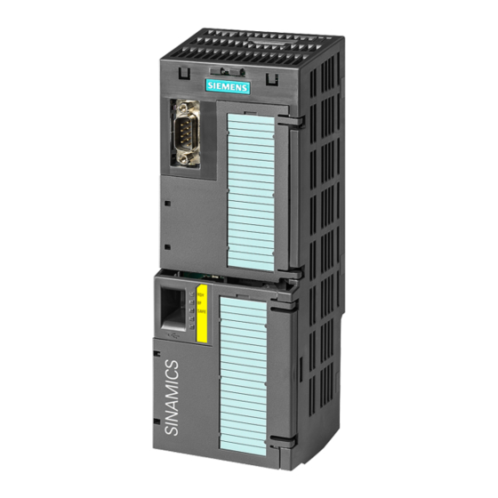
Page 13: Control Unit
Interface to the Power Module Fastening clips Please ensure that this is the correct device for your application. An overview of the various control unit versions and their differen- tiation can be found in the official SINAMICS G120 brochure at http://www.siemens.com/ sinamics-g120/printmaterial Note... -
Page 14: Operator Panels (Bop-2 And Iop)
It is available in various versions and can also be used drive- externally for series commissioning and quick on-site diagnosis. BOP-2 Seven operating buttons Graphical display Display Navigation wheel Release catch Five operating buttons Door mounting screw USB connection recess RS232 connector Product rating label Inverter family SINAMICS G120: Components... -
Page 15: Power Module
Mounting and wiring Before starting assembly, check to ensure that the following conditions have been met: • All required components, tools, and small parts have been gathered. • All required cables and lines have been laid in accordance with specifications. •... - Page 16 • Connect the phases and the earth conductor to the pluggable terminal clamps U2, V2, W2, and PE. Wiring the motor • Unscrew the cover to the terminal box on the motor (the inside cover of Siemens motors illustrates the possible wiring for the Star connection and the Delta connection).
- Page 17 Motor lines represent interfering transmitters. As a result, you should use shielded cable in order to meet the corresponding electromagnetic compatibility requirements. The cable lengths that can be used depend upon the following: ‒ Operating environment ‒ Inverter being used ‒...
-
Page 18: Control Unit
• Wire the “Faults” and “Warning” LEDs to digital outputs 19 and 21. • Connect the negative pole to terminal 28. Display for frequency output: • Connect the positive pole to 12. • Connect the negative pole to 13. The wiring is now complete. Inverter family SINAMICS G120: Mounting and wiring... -
Page 20: Operator Panels (Bop-2 And Iop)
• Remove the cover of the RS232 connection by lifting it up and sliding it to the side. • Place the bottom edge of the IOP/BOP-2 casing into the lower recess of the Control Unit housing. • Push the IOP/BOP-2 toward the Control Unit until the release-catch clicks into place. Inverter family SINAMICS G120: Mounting and wiring... - Page 21 Mounting the IOP or BOP-2 in a cabinet door The operator panels can easily be mounted in a control cabinet door with just a few manual operations using the optionally available door mounting kit. Degree of protection IP55 / UL type 12 is achieved when mounting them in the control cabinet door.
- Page 22 In this section you will learn more about the use of operator panels to control the inverter locally on site. First, you’ll learn how to use the Basic Operator Panel 2 (BOP-2) to set up parameters for the invert- er and the attached motor and how to operate the inverter with the BOP-2.
- Page 23 Basic Operator Panel (BOP-2) Intelligent Operator Panel (IOP)
-
Page 24: The Bop-2 Display
Basic functions The Operator Panel is the input and display instrument for controlling the inverter. It is used in stand-alone operation, in other words, locally, on the device, integrated in the cabinet door, or as handheld version for series setup (IOP). The BOP-2 display The BOP-2 is used to commission, diagnose (troubleshoot), and display the status of the inverter. - Page 25 Working with BOP-2 Seven buttons make up the operator panel. For setup and parameterization, only the Up and Down, OK and ESC buttons are relevant. For local operation the ON, OFF, and HAND / AUTO keys are needed. ESC key Up key Down key OK key...
-
Page 26: Operating Pattern And Menu Structure
Operating pattern To better understand the functionality of the buttons, you should be acquainted with the oper- ating pattern: the Basic Operator Panel gives you access to a parameter list, which ranges from 0 to 9,899. Stored behind the parameters are parameter values that control the operation of the motor. - Page 27 ESC (move to previous digit), UP (increase value), and DOWN (decrease value). A complete list of all parameters can be found in the “Parameter Manual: Control Units – CU240E/B-2” available on the Internet as a down- load at http://support.automation. siemens.com/WW/view/en/ 30563628/133300 Note...
- Page 28 “A”. A detailed list of the Fault and Alarm messages can be found in the “Parameter Manual Control Units CU240E/B-2” available on the Internet as a download at http:// support.automation. siemens.com/WW/view/ en/30563628/133300 Operator Panels BOP-2 and IOP: Working with BOP-2 Note...
- Page 29 Menu structure Monitor The Monitor menu allows the user to easily access a variety of screens that display the actual status of the inverter/motor system. Control The Control menu allows the user to access the following functions of the inverter: •...
- Page 30 Quick commissioning The following descriptions show how to set up the drive using the quick commissioning wizard integrated in the BOP-2. Starting quick commissioning • Press ESC to enter the menu selection. • Use the UP and DOWN buttons to move the menu cursor to the word “Setup” and press OK. •...
- Page 31 Control mode (P1300) • Press OK to modify the parameter value CTRL MOD. • The upper row shows the control mode associated with the actual parameter value below. • Choose control mode value by pressing UP or DOWN. • See how the control mode name in the upper row changes accordingly. •...
-
Page 32: Entering Motor Data
Entering motor data The values for the next parameter settings can be found on the rating plate of your motor. Please set the motor data parameters according to the picture below. P304 = MOT VOLT = Motor voltage P305 = MOT CURR = Motor rated current P307 = MOT POW = Motor rated power P311 = MOT RPM = Motor rated speed Once the motor rated speed has been adjusted, you have completed... -
Page 33: Motor Data Identification
Motor data identification After entering the motor data, the wizards asks you to activate the motor data identification. Motor ID is recommended for a live verification and optimization of the data that you have entered. The motor data identification initiates a “measurement” of the connected motor. In the process, the data previously calculated in the inverter is compared to the actual motor data and they are adapted to one another. -
Page 34: Setting Additional Parameters
Command source, setpoint source, and application parameters With the next step, you can select whether the Basic Operator Panel or the terminal should be the command source (parameter P700). In the case of the CU240E-2 being used here, the termi- nals are set as the default for the command source. - Page 35 The inverter can now be turned on using digital input DI 0. The setpoint source is specified as the potentiometer. Refer to the “Parameter Manual: Control Units – CU240E/B-2” for a description of the control modes and their corresponding parameter settings at http://support.automa- tion.siemens.com/WW/view/ en/30563628/133300 Note Note...
-
Page 36: Using Fixed Frequencies
Application case You’ll now see how you can use the Basic Operator Panel 2 to make additional adjustments. In specific applications, it is meaningful, for example, to control the motor using fixed frequencies. Fixed frequencies are preset at digital inputs DI 3, DI 4, and DI 5. Therefore, the setpoint source must be switched from the potentiometer to the digital inputs on the terminals. -
Page 37: Testing The Application
Testing the application Now check to see how the motor reacts to the digital inputs being actuated. To do so, flip switch DI 0 (start the motor) and DI 3 (activate the first fixed frequency). The motor starts. Now use the Basic Operator Panel 2 to enter the menu function MONITORING by pressing OK. - Page 38 Intelligent Operator Panel With the Intelligent Operation Panel, you can set the inverter parameters, put the inverter into operation, monitor the ongoing operation of the motor, and get valuable information about faults and alarms. All these functions can be accessed without expert knowledge. The main ad- vantages are as follows: Fast commissioning without expert knowledge •...
-
Page 39: The Device
The device The IOP is a menu-driven device. Its functionality is structured by three options: [Wizards] Assists you to set up standard applications [Control] Allows you to change setpoint value, turning direction, or to activate the real-time jog function [Menu] Gives you access to all possible functionalities The display All necessary information is displayed in user-friendly plain text or icons. -
Page 40: Working With Iop
Working with IOP The IOP is operated mainly by using the push-wheel. The five additional buttons make it possible to display certain values or to switch between manual and auto mode. The buttons are called: ON key, OFF key, ESC key, Info key, and HAND / AUTO key. Turning changes the selection Pressing confirms the selection Starts the motor in manual mode... -
Page 41: The Wizards
The wizards There are several wizards that allow you to set up various functions and commission the invert- er. They navigate you interactively through the parameterization of standard applications. The wizards are accessed from the wizards menu, at the bottom-left of the status screen. Example: Basic commissioning •... -
Page 42: Accessing Diagnostics
Accessing diagnostics If you want to find out which input and output devices are connected to the inverter, simply navi- gate to the diagnostics menu and select the I / O STATUS. This option displays a list of the digital and analog inputs and outputs of the inverter. - Page 43 Getting information on active faults • Use the wheel to highlight the word MENU. • Confirm by pressing OK. • Choose DIAGNOSTICS. • Confirm by pressing OK. • Select ACTIVE FAULTS / ALARMS. Menu Diagnostics Active Faults/Alarms Now all active fault messages that have not yet been acknowledged are displayed. To get further information you can highlight each one and press INFO.
- Page 44 PC or PG to the inverter and acquaint you with the STARTER software. You will then set the pa- rameters of the SINAMICS G120 inverter with the software and start it up. In the following chapter, you will see how to do this with a PC.
- Page 45 STARTER software and PC...
- Page 46 Mounting and preparation The optional PC Connection Kit 2 is required to set up the parameters using a PC. The kit consists of two components. A connecting cable The STARTER software on DVD STARTER software and PC: Mounting and preparation...
- Page 47 In addition to the hardware, you’ll also need the STARTER software, which is included on a DVD in the PC Connection Kit 2. Install the STARTER software on your PC following the explanations of the setup wizard. The STARTER is also available as a download at: http://support. automation.siemens.com/WW/ view/en/10804985/133100 Note...
-
Page 48: Pc Preparation
COM port smaller than eight (COM1 … COM7). You need to remember that number for later use with the STARTER. Browse to your computer’s control panel. Select "Hardware." Click on “Device Manager.” Check if “Sinamics G120 USB COM Emulation” has an address higher than COM7. STARTER software and PC: Mounting and preparation... - Page 49 In case it is higher than eight, double-click the connection. Enter the "Advanced" section. Change the COM address by choosing any free small COM address. Confirm your selection with OK.
-
Page 50: Creating A Starter Project
Creating a STARTER project with the Project Wizard After installation is complete, switch on the inverter’s power supply and start the program. The Project Wizard opens automatically. The wizard will help you create your first project. Select the “Find drive units online” button. Give the project a name and click “Continue.”... - Page 51 Click the “Change and test” button to set up the PC interface. Select “PC COM-Port (USS)" and click “Properties.”...
- Page 52 Installing the PC COM-Port (USS) In some cases, you might have to add the PC COM-Port (USS) to your list. To do this, click “Select,” highlight the port in the appearing list, and add it with a mouse click on “Install.” Close the window.
- Page 53 Specify the interface and enter the baud rate 115,200 in the “Interface” tab. Select “Automatic mode” in the “RS485” tab and close the properties dialog field by clicking “OK.”...
- Page 54 Click “Continue” to start the search for online units: a preview of the project tree will appear in the summary. Close the Project Wizard by selecting “Complete.” STARTER software and PC: Mounting and preparation...
-
Page 55: Starter User Interface
STARTER user interface The inverter is now integrated into the project tree and the parameters can be set up using the STARTER software. Project tree Icon “Connect to target system” Program menu Connection mode Toolbar with special features Work area... -
Page 56: Uploading Inverter Data
Uploading inverter data By clicking the “Connect to target system” button, you establish an online connection between the PC and the inverter. Click icon “Connect to target system.” A dialog window opens and the current inverter data is displayed. Click the “Load HW configuration to PG” button. In addition, the blue highlighted “Offline mode”... - Page 57 Parameterization The STARTER software and the inverter are now connected to each other. You can now begin to parameterize your inverter. Double-click on the inverter icon in the project tree: a directory folder opens. Double-click on the first icon: the configuration window in the work area opens. Click “Wizard”...
-
Page 58: Configuration Wizard
Configuration Wizard The Configuration Wizard guides you step by step through the following parameters: • Control structure • Defaults of the setpoint source and the command source • Motor • Motor data • Drive functions • Important parameters • Calculation of the motor data •... - Page 59 By clicking “Continue” you get to the next configuration step. Start by setting the control method. Define the command and setpoint source. Select the motor type.
- Page 60 Input motor data from the rating plate. Select “Identification of all parameters in standstill” for motor data identification. Alarm message The warning message “warning 541” appears. The message indicates that the motor might turn when motor data identification is performed. STARTER software and PC: Parameterization...
- Page 61 Enter maximum current – normally 200%, minimum and maximum frequency, ramp-up and ramp-down time, and OFF ramp-down time (the time the motor needs to stop in the case of an emergency shut-off). After clicking “Next,” the calculating of the motor data starts. This concludes the parameterization with the Configura- tion Wizard.
-
Page 62: Motor Data Identification
Motor data identification Before the inverter can be operated, you must start the motor from the PC. Performing this action will activate the parameters. The first step is to assume control priority. Open the “Commissioning” entry in the project tree. Double-click “Control panel”... - Page 63 A setup window for command transfer opens: accept the displayed values and safety instructions. In the workbench area, place a checkmark next to “Enables.” Now the STARTER software has control authority for the attached motor. Click the green button to start the motor. Motor data identification is processed.
-
Page 64: Safety Integrated Engineering With Starter
SS1 (Safe Stop 1) and SLS (Safely Limited Speed) also integrated – no encoder needed! You can find more information on those advanced features in the SINAMICS Safety brochure at http://www.automation. siemens.com/infocenter/ order_form.aspx?tab=3& nodekey=key_518445&l ang=en STARTER software and PC: Safety Integrated Note... - Page 65 This world- wide unique feature saves installa- tion and engineering time, reduces system costs and saves space. For further instructions consult the Safety functions manual SINAMICS G120 using the Siemens Product In- formation System (Prodis) at http:// support.automation.siemens.com/ WW/view/en/22339653/130000 Note Note...
-
Page 66: Setting Setpoint Specifications
Application cases Before returning control authority from the STARTER software to the terminal, you should try controlling the motor from the PC. Setting setpoint specifications Input 1,500 1/min in the “Setpoint specifications” box. Start the motor: the motor runs at 1,500 1/min. Adjust the frequency with the slider. -
Page 67: Closing A Project And Saving Data
Closing a project and saving data Unintentional disruption of the online connection between the inverter and the PC due to a power outage, for example, leads to the loss of the parameter settings. As a result, STARTER offers various possibilities for protecting your parameter settings. Double-click the “Drive Navigator”... -
Page 68: Restoring Factory Settings
Restoring factory settings Before you can start setup for your specific application, you should reset your inverter to factory settings. Double-click the “Drive navigator” in the project tree. Select “Commissioning” in the work area. Click “Restore factory settings.” STARTER software and PC: Application cases... - Page 69 The security query that is now displayed lets you know that all settings you have made will be reset. Using the checkbox query, you will have the opportunity beforehand to save your settings to the inverter’s ROM memory. Click “OK” to reset all inverter settings to the factory setting. Click “Disconnect from target system”...
- Page 70 Congratulations! You have mastered the SINAMICS G120 Training Booklet V2.0. Thank you for your time and efforts. We hope that this tutorial has addressed all the questions you had and was useful to you. More detailed information can be found online.
-
Page 71: Download Overview
Additional information on parameters “Parameter Manual: Control Units – CU240B/E-2” available on the Internet as a download at http://support.automation.siemens.com/WW/view/en/30563628/133300 Detailed information about SINAMICS G120 “Operating Instructions: Control Unit CU240E” available on the Internet as a download at http://support.automation.siemens.com/WW/view/en/30563628/133300 STARTER Software STARTER is available as a download at http://support.automation.siemens.com/WW/view/en/10804985/133100... - Page 72 Ordernumber.: E80001-Y910-P210-X-7600 without prior notice. © Siemens AG 2010 All product designations may be trademarks or product names of Siemens AG or supplier companies whose use by third parties for www.siemens.com/sinamics-g120 their own purposes could violate the rights of the owners.
Need help?
Do you have a question about the SINAMICS G120 and is the answer not in the manual?
Questions and answers