Table of Contents
Advertisement
This manual is for:
Record model number and serial number of your planter along with date purchased:
Monitor Serial Number _______________________________________________
Measured Pulses Per Mile/Km (Radar Distance Sensor) ____________________
Measured Pulses Per Mile/ Km (Magnetic Distance Sensor) _________________
SERIAL NUMBER
Record your serial number and purchase date above for quick reference.
The serial number provides important information about your planter and is required to obtain correct replacement
parts. Always provide planter model and serial number to your Kinze Dealer when ordering parts or anytime
correspondence is made with Kinze Manufacturing, Inc.
Kinze
, the Kinze
®
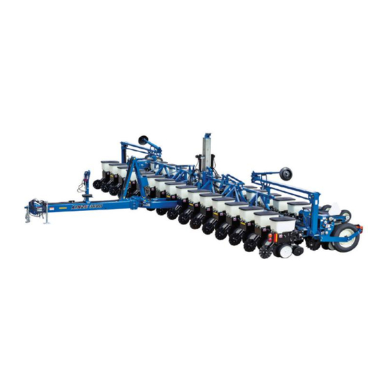
MODEL 3600
PIVOT FOLD PLANTER
OPERATOR'S MANUAL
M0259
Model 3600 Twin-Line
- 12 Row 30" and 16 Row 30" "Y" and "T" Hitch Conventional and Bulk Fill
Machines; 2015 Production Year and on
- 16 Row 7.5" Twin Row "Y" Hitch; 2015 Production Year and on
Model Number __________________________________
Serial Number ___________________________________
Date Purchased __________________________________
Serial number plate location - R.H. Wing
logo, Twin-Line
and Interplant
®
®
Rev. 9/17
Planters
®
3600
are registered trademarks of Kinze Manufacturing, Inc.
®
Advertisement
Table of Contents

Related Manuals for Kinze 3600


Summary of Contents for Kinze 3600
- Page 1 The serial number provides important information about your planter and is required to obtain correct replacement parts. Always provide planter model and serial number to your Kinze Dealer when ordering parts or anytime correspondence is made with Kinze Manufacturing, Inc.
-
Page 2: General Information
WARRANTY The Kinze Limited Warranty for your new machine is stated on the retail purchaser’s copy of the Warranty And Delivery Receipt form. Additional copies of the Limited Warranty can be obtained through your Kinze Dealer. Warranty, within the warranty period, is provided as part of Kinze’s support program for registered Kinze products which have been operated and maintained as described in this manual. - Page 3 Predelivery/Delivery Checklist M0259-01 Model 3600 TO THE DEALER Predelivery service includes assembly, lubrication, adjustment and test. This service helps ensure planter is delivered to retail customer/end user ready for field use. PREDELIVERY CHECKLIST Use the following checklist after planter is completely assembled. Check off each item as it is found satisfactory or after proper adjustment is made.
- Page 4 Replace if damaged or missing. Check safety/warning lights are working properly. (Signature Of Follow-Up Person/Dealer Name/Date) All registrations must be submitted online at “business.kinze.com” within 5 business days of delivery. Retain a copy of this form for auditing purposes. Tear Along Perforation...
-
Page 5: Table Of Contents
Granular Chemical Banding Options ....3-25 Kinze ISOBUS Option ......2-27 Granular Chemical Bander Shield . - Page 6 Table of Contents Model 3600 M0259-01 Residue Wheel Attachment for Spring Tooth Incorporator ......6-25 Notched Single Disc Fertilizer Opener ... . . 4-4...
-
Page 7: To The Owner
M0259-01 Model 3600 Kinze Manufacturing, Inc. thanks you for your patronage. We appreciate your confidence in Kinze farm machinery. Your Kinze planter has been carefully designed to provide dependable operation in return for your investment. This manual has been prepared to aid you in the operation and maintenance of the planter. It should be considered a permanent part of the machine and remain with the machine when you sell it. - Page 8 NOTE: Some photos in this manual may have been taken of prototype machines. Production machines may vary in appearance. NOTE: Some photos and illustrations in this manual show optional attachments installed. Contact your Kinze Dealer for purchase of optional attachments.
-
Page 9: Specifications
Specifications M0259-01 Model 3600 Specification Conventional Hoppers Number of Rows 12R N 30 Y/T 12R W 36-38 Y 16R N 30 Y/T 16 R 7.5" Y Weight Empty 12,780 lb (5,796.91 kg) - 13,522 lb 15,730 lb (7,135.00 kg) - 19,750 lb 13,185 lb (5,980.62 kg) - Page 10 Model 3600 M0259-01 TRACTOR HYDRAULIC REQUIREMENTS Configuration No Optional Pumps Tractor Mounted PTO Pump Mechanical Meter 2 SCV 15 gpm min. Vacuum Meter 3 SCV 30 gpm min. 2 SCV 15 gpm min. Bulk Fill (with Mechanical Meter) 3 SCV 25 gpm min.
-
Page 11: General Safety Rules
General Safety Rules M0259-01 Model 3600 1. Read and understand instructions provided in this 15. Use of aftermarket hydraulic, electric, or PTO drives manual and warning labels. Review these instructions may create serious safety hazards to you and people frequently! nearby. -
Page 12: Safety Precautions
Safety Precautions Model 3600 M0259-01 Following are some common hazard warnings associated with this equipment. Pay close attention to all safety, operating, and maintenance information in this manual and decals applied to your equipment. Contacting or coming close to power... - Page 13 M0259-01 Model 3600 SAFETY SIGNS AND DECALS All safety/warning lights, reflective WARNING decals, and SMV sign must be in place and visible before transporting machine on public roads or death, serious injury, and damage to property and equipment may result. Check federal, state/ provincial, and local regulations before transporting equipment on public roads.
- Page 14 This page left blank intentionally.
-
Page 15: Machine Operation
Machine Operation M0259-01 Model 3600 MANUAL SAFETY LOCKUP Uncontrolled movement of equipment WARNING can cause loss of control and could result in death, serious injury, or damage to property and equipment. Install all safety pins before transporting equipment. Manual safety lockup in storage position Manual safety lockup in transport position Remove manual safety lockup and store on L.H. -
Page 16: Tongue Safety Pin
Machine Operation Model 3600 M0259-01 Uncontrolled movement of equipment WARNING can cause loss of control and could result in death, serious injury, or damage to property and equipment. Install all safety pins before transporting equipment. TONGUE SAFETY PIN Tongue safety pin installed for transport Tongue safety pin stored for field operation Never transport planter without installing tongue safety pin. -
Page 17: Initial Preparation
Machine Operation M0259-01 Model 3600 INITIAL PREPARATION Following information is general in nature to aid in preparation of tractor and planter for use, and to provide general operating procedures. Operator experience, familiarity with the machine, and the following information should combine for efficient planter operation and good working habits. -
Page 18: Tractor Requirements
Machine Operation Model 3600 M0259-01 Contact drive 1. Torque transport wheel 5∕8"- 18 lug nuts to 180 ft-lb (244 N-m). 2. Inflate tires to the following specifications: Transport (center section) 255-70R 22.5 (“224” rim) 75 psi (517.1 kPa) recommended/75 psi (517.1 kPa) max. -
Page 19: Tractor Mounted Pto Pump And Oil Cooler Option
Machine Operation M0259-01 Model 3600 TRACTOR MOUNTED PTO PUMP AND OIL COOLER OPTION The tractor mounted PTO pump and oil cooler option is for tractors with less than required hydraulic output needed Oil cooler to operate hydraulic-driven vacuum fan and other planter hydraulic requirements. -
Page 20: Tractor Preparation And Hookup
Machine Operation Model 3600 M0259-01 TRACTOR PREPARATION AND HOOKUP 1. Adjust tractor drawbar 13-17 inches above ground with hitch pin hole directly below PTO shaft center line. Make sure drawbar is in a stationary position. 2. Install control console on tractor in a convenient location within easy reach of operator and close to hydraulic controls. - Page 21 Machine Operation M0259-01 Model 3600 Safety chain must be used to keep planter and tractor connected in case of a hitch pin/drawbar failure. Attach safety chain at an unused clevis mounting hole on the planter hitch. Torque hardware to 840 ft-lb (1138.8 N-m).
- Page 22 NOTE: Set adjustable flow outlet (SCV) to full flow position. For tractors not equipped with a method for finite adjustment of hydraulic flow, Flow Control Needle Valve Kit G1K426 is available from Kinze Repair Parts through your Kinze Dealer. G1K426 needle valve kit 9/14...
-
Page 23: Level Planter
Machine Operation M0259-01 Model 3600 6. Connect ASABE Standards 7 terminal connector for safety/warning lights on planter to ASABE Standards receptacle on tractor. If your tractor is not equipped with an ASABE Standards receptacle, check with your tractor manufacturer for availability. Check warning lights on planter work in conjunction with warning lights on tractor. -
Page 24: Ridge Planting
Machine Operation Model 3600 M0259-01 4. Field check planter. Field and actual planting conditions dictate which transport wheel setting to use so row unit parallel arms are parallel with ground. It may be necessary to lower ground drive wheels to ensure level lateral toolbar operation if transport wheels are set in one of the two lower sets of holes. -
Page 25: Contact Wheel Spring Adjustment
Machine Operation M0259-01 Model 3600 CONTACT WHEEL SPRING ADJUSTMENT 8" Spring length measurement (Factory setting) Contact drive springs There are two down pressure springs on each contact drive wheel. Spring tension is factory set to approximately 200 lb (90.7 kg) of down force at tire contact point and should require no further adjustment. -
Page 26: Seed Rate Transmission Adjustment
Machine Operation Model 3600 M0259-01 SEED RATE TRANSMISSION ADJUSTMENT Planting population rate changes are made using seed rate transmissions at each end of planter. Seed rate transmission allows quick and easy sprocket changes to obtain desired Drive sprocket planting population. Sprockets are exchanged with those from sprocket storage rod bolted to transmission by removing lynch pins on hexagon shafts. -
Page 27: Hydraulic Seed Rate Drive
Machine Operation M0259-01 Model 3600 HYDRAULIC SEED RATE DRIVE Refer to Ag Leader Integra or KINZE Cobalt operation manuals for information on setting and controlling hydraulic seed rate system. HALL EFFECT SENSOR (HYDRAULIC DRIVE ONLY) Set Hall effect sensor within ⅛" of pick-up disc. -
Page 28: Hydraulic/Electric Operation
Two-speed point row clutch control box Model 3600 planters operate from three dual remote (SCV) hydraulic outlets and tractor mounted control console. One SCV and a control console switch operate raise to transport function. A second SCV and control console switches operate row markers and fold/unfold functions. -
Page 29: Transport To Field Sequence
Machine Operation M0259-01 Model 3600 TRANSPORT TO FIELD SEQUENCE Position planter in a relatively flat open area. Avoid an area with furrows, etc. SUMMARIZED TRANSPORT TO FIELD SEQUENCE • Remove tongue safety pin. • Remove transport latch locking pin. • Remove manual safety lockup. - Page 30 Machine Operation Model 3600 M0259-01 3. Remove manual safety lockup from under front center lift cylinder and place it in storage location on left side of planter axle. Storage position Hold control console “ROTATE/TONGUE” switch in “ROTATE” and operate hydraulic control to unfold planter.
- Page 31 Machine Operation M0259-01 Model 3600 8. Hold hydraulic control (to lower planter) to rephase planter lift cylinders. Time to rephase system may vary due to tractor hydraulic flow and/or oil temperature. Normally 5 to 20 seconds is adequate to rephase system.
-
Page 32: Field Operation
Machine Operation Model 3600 M0259-01 FIELD OPERATION Contacting or coming close to power DANGER lines or other high energy sources will cause death or serious injury. Keep away from power lines or high energy sources at all times. Raise planter out of ground when making... -
Page 33: Field To Transport Sequence
Machine Operation M0259-01 Model 3600 FIELD TO TRANSPORT SEQUENCE Position planter in a relatively flat area. Avoid areas with furrows, etc. SUMMARIZED FIELD TO TRANSPORT SEQUENCE • Install row marker lockups. • Raise planter to raised field position. • Extend tongue. - Page 34 Machine Operation Model 3600 M0259-01 5. Hold control console “RAISE/WING LOCK” switch in “RAISE” and operate hydraulic control until two center lift cylinders are fully extended and safety hook at top of center section rotates into locking position. 6. Lower planter onto safety hook using hydraulic control.
-
Page 35: Digital Vacuum Readout
NOTE: Fan turns at a reduced speed If reverse pressure is applied. VACUUM METER SYSTEM Kinze vacuum meter seed metering system includes seed meters, seed discs, and an air system consisting of a hydraulic driven vacuum fan which draws air through manifolds, hoses, and seed meters on each row unit. -
Page 36: Analog Vacuum Or Pressure Gauge
Machine Operation Model 3600 M0259-01 ANALOG VACUUM OR PRESSURE GAUGE Analog vacuum or pressure gauge connects directly to vacuum meter (vacuum) or bulk fill (pressure) manifold and is teed into digital sending units. Only adjustment is to “zero” needle with no vacuum or KILOPASCALS pressure present. -
Page 37: Bulk Fill Entrainer Access
Machine Operation M0259-01 Model 3600 1. Before filling hoppers refer to “Row Unit Operation” for additives information. Fill hoppers with seed, latch lids, and secure with pin. 2. Start bulk fill system with tractor engine at idle. Counterclockwise to open 3. -
Page 38: Bulk Fill Scale Package Option
• Provides seed weight or estimated acres remaining for each bulk fill hopper. • Displays total (gross) seed weight or estimated acres remaining for both hoppers combined. • Warns operator when seed goes below a pre-defined level (when using a Kinze Vision display). UP/DOWN arrow buttons... - Page 39 Machine Operation M0259-01 Model 3600 SETUP BULK FILL SCALE PACKAGE DISPLAY Press SET-UP button. 2. First setup screen displays and ALARM LEVEL box is highlighted. 3. Press SELECT button. 4. Press UP or DOWN arrows to change alarm weight level.
-
Page 40: Rock Guards
Machine Operation Model 3600 M0259-01 ENTER SEED INFORMATION 1. Highlight and select either L (left) or R (right) for the appropriate input screen. 2. At input screen, L or R side is indicated at left side of screen and seed weight or acres remaining is on right side. -
Page 41: Ag Leader Integra Display
NOTE: See InCommand operator manual for installation and programming. KINZE ISOBUS OPTION Kinze ISOBUS option consists of a planter monitor module (PMM), and planter control module (PCM). Kinze planters will communicate directly with most ISO compatible monitors. See the Kinze ISOBUS manual for more information. 2-27... -
Page 42: Row Marker Operation
Machine Operation Model 3600 M0259-01 ROW MARKER OPERATION Contacting or coming close to power DANGER lines or other high energy sources will cause death or serious injury. Keep away from power lines or high energy sources at all times. Row marker solenoid valves (Cover removed) Marker switch Two solenoid valves on valve block at rear R.H. -
Page 43: Row Marker Speed Adjustment
Machine Operation M0259-01 Model 3600 ROW MARKER SPEED ADJUSTMENT Excessive row marker travel speed NOTICE can damage row markers. Adjust flow controls before row markers are first used. Marker hydraulic system includes two flow control valves. One flow control valve sets lowering speed and one sets raising speed of both markers. -
Page 44: Row Marker Adjustments
5. Loosen hardware and move assembly as required. 6. Tighten bolts to specified torque. 7. Do a field test to ensure markers are properly adjusted. NOTE: A notched marker blade is available from Kinze through your Kinze Dealer for use in more severe no till conditions. 2-30... -
Page 45: Row Marker Even-Row Length Adjustment
Machine Operation M0259-01 Model 3600 ROW MARKER EVEN-ROW LENGTH ADJUSTMENT Adjust marker extensions as shown below when using even-row push row unit option. To center of outer row unit Planter centerline To center of outer row unit Center Of 15"... -
Page 46: Point Row Clutches
Machine Operation Model 3600 M0259-01 POINT ROW CLUTCHES L.H. point row clutch switch R.H. point row clutch 10 amp time delay fuse switch 10 amp time delay fuse Point row clutch switch Single point row clutch control box Point row clutch Electric-activated clutches disengage drive on either half of planter for finishing up fields or for long point row situations. -
Page 47: Two-Speed Point Row Clutches
Machine Operation M0259-01 Model 3600 TWO-SPEED POINT ROW CLUTCHES Module Extension Two-Speed Clutch Drive sprocket Two-speed point row clutch Driven sprocket Optional Two-Speed Point Row Clutch Package allows on-the-go population rate adjustment and capability to shut off either half of planter for finishing up fields or for long point row situations. -
Page 48: Auxiliary Hydraulic Option
Machine Operation Model 3600 M0259-01 AUXILIARY HYDRAULIC OPTION A customer-supplied auxiliary hydraulic option provides 10 GPM of oil flow at rear of planter for powering fertilizer attachments, bulk seed handling equipment, etc. Two customer-supplied solenoid valve kits (G1K275) are required to activate auxiliary hydraulic option with control console auxiliary switch. -
Page 49: Rear Trailer Hitch
Machine Operation M0259-01 Model 3600 REAR TRAILER HITCH Rear trailer hitch can tow a 3 or 4 wheel wagon behind planter. A spring, chain, and mounting bracket supports a 1¼" feed hose from hitch to piston pump. This extra length or loop is required to allow for planter to move into transport position without stretching hose. -
Page 50: Field Test
Machine Operation Model 3600 M0259-01 FIELD TEST Perform a field test with any change of field and/or planting conditions, seed size or planter adjustment to ensure proper seed placement and operation of row units. Check planter for front to rear and lateral level operation. See “Level Planter”. -
Page 51: Determining Pounds Per Acre (Brush-Type Meter)
Machine Operation M0259-01 Model 3600 3. Measure 1∕1000 of an acre. See chart for correct distance for row width being planted. For example, if planting 30" rows 1∕1000 of an acre would be 17' 5". 1∕1000 Acre Seed Population Count Row Width/Distance Row Width 7.5"TR/15"... -
Page 52: Field Check Granular Chemical Application
Machine Operation Model 3600 M0259-01 FIELD CHECK GRANULAR CHEMICAL APPLICATION Temperature, humidity, speed, ground conditions, flowability of different material, or meter obstructions can affect granular chemical rate of delivery. Agricultural chemicals can cause death WARNING or serious injury to persons, animals, and plants or seriously damage soil, equipment, or property. -
Page 53: Row Unit Operation
Row Unit Operation M0259-01 Model 3600 PLANTING DEPTH Planting Planting depth is maintained by adjustable row unit gauge depth adjustment wheels. Depth adjustment range is approximately ½" to 3½". handle Raise planter to remove weight from wheels. Push down on depth adjustment handle and reposition it forward to decrease or rearward to increase planting depth. -
Page 54: Drag Closing Attachment
Row Unit Operation Model 3600 M0259-01 DRAG CLOSING ATTACHMENT Drag closing attachment pulls loose soil over seed trench. NOTE: Use of a seed firming wheel or other seed firming Eccentric device is recommended with drag closing attachment. bushing Front and rear adjustment is made using slotted holes in blades. -
Page 55: Seed Hoppers
Row Unit Operation M0259-01 Model 3600 SEED HOPPERS Mechanical seed hopper has a capacity of 1.9 bushels. Vacuum seed hopper has a capacity of 1.75 bushels. Use clean seed and make certain there are no foreign objects inside when filling seed hopper. Replace hopper lids after hoppers are filled to prevent accumulation of dust or dirt in seed meter which can cause premature wear. -
Page 56: Row Unit Chain Routing
Row Unit Operation Model 3600 M0259-01 ROW UNIT CHAIN ROUTING Row unit drive chains must be properly tensioned and aligned for proper operation and to minimize wear. Inspect and replace weak, worn or broken springs, idlers, and idler bushings. Mechanical pull row unit meter drive... -
Page 57: Quick Adjustable Down Force Springs Option (Standard Or Heavy Duty)
Row Unit Operation M0259-01 Model 3600 QUICK ADJUSTABLE DOWN FORCE SPRINGS OPTION (STANDARD OR HEAVY DUTY) Standard and heavy duty quick adjustable down force springs are available in increase penetration in hard soil and keep row unit from bouncing in rough field conditions. Two springs per row, one on each side parallel arms, are used unless equipped with row unit mounted no till coulters. - Page 58 NOTE: If additional down pressure is needed with the Pneumatic Down Pressure Package, assist springs are available through your Kinze dealer. One spring is installed on the outer side of the parallel arms on each side of the row unit as shown below.
-
Page 59: Interplant Push Row Unit Clutch Sprocket
Row Unit Operation M0259-01 Model 3600 FIELD OPERATION NOTE: Adjust down pressure with planter lowered and row openers in ground for most accurate adjustment. Pressure can be adjusted from tractor using control console, or at planter using manual control valves on compressor assembly. -
Page 60: Interplant Push Row Unit Lockups
Row Unit Operation Model 3600 M0259-01 INTERPLANT PUSH ROW UNIT LOCKUPS Push row unit lockups lock interplant row units in the raised position. Improper lifting of row units can cause CAUTION serious injury. An empty row unit requires minimum 90 lb (40.8 kg) lift. -
Page 61: Interplant Push Row Unit Vacuum Hose Shutoff
Row Unit Operation M0259-01 Model 3600 To lock in raised position: To release lockups: 1. Set row unit down pressure springs to minimum 1. Lower the planter to the planting position. setting. 2. On each push row unit lockup, flip the spring tab 2. -
Page 62: Brush-Type Seed Meter
Row Unit Operation Model 3600 M0259-01 BRUSH-TYPE SEED METER Upper Disc Color-Code Brush Seed Size Crop (Disc Part No.) Retainer Cells Range *Lubricant Soybean Black GD11122 2200 to 4000 Graphite (GA5794) seeds/lb. Talc Graphite Specialty Soybean Dark Blue GD11122 1400 to 2200 (GA6184) seeds/lb. -
Page 63: Finger Pickup Seed Meter
Row Unit Operation M0259-01 Model 3600 Turn seed disc counterclockwise when installing on meter hub while tightening two wing nuts that retain disc. Seed disc should have slight resistance when rotated counterclockwise after wing nuts are tight. Brush-type seed meter attaches to seed hopper same as finger pickup seed meter. -
Page 64: Vacuum Settings
Row Unit Operation Model 3600 M0259-01 VACUUM SETTINGS Vacuum Seed Ejector Singulator Setting **Seed Disc Wheel Seed Size Zone Inches of Crop Disc Kit Part No. (Color) Cells Range Setting Water (kPa) Lubricant Graphite* Corn B0678 1 row 35-70 lbs/80k... - Page 65 Row Unit Operation M0259-01 Model 3600 NOTE: See for more information. Always field check seed population "Field Check Seed Population" on page 2-32 to ensure planting rates are correct. NOTE: Singulator settings are marked from 0 - 3. NOTE: Mixing seed sizes and shapes affects meter performance. Use consistent seed size and shape.
- Page 66 Row Unit Operation Model 3600 M0259-01 Ejector NOTE: Damaged seed or seed containing foreign material will cause plugging of seed disc orifices and require more frequent seed meter cleanout to prevent underplanting. Wheel-Type Ejectors Wheel-type ejectors expel seed remants from seed disc orifices. These ejectors are disc specific and colored coded to match disc.
-
Page 67: Seed Meter Cleanout
Row Unit Operation M0259-01 Model 3600 4. Adjust vacuum level to initial setting according to tables on page. NOTE: Vacuum reading will be much lower when seed disc cells are empty. Load all seed cells before setting vacuum level. NOTE: Operate vacuum fan 3-5 minutes to bring oil up to normal operating temperature prior to making final vacuum level adjustment. -
Page 68: Additives
Row Unit Operation Model 3600 M0259-01 ADDITIVES Lubricant Application Rate The use of graphite is recommended to promote seed flow, provide lubrication for the seed meter and to help dissipate static charge Graphite buildup. Among the available dry seed lubricants graphite is the most Conventional Hoppers 1 Tbs./Hopper Fill... -
Page 69: Bayer Fluency Agent
This product, as tested by Kinze, is compatible with Kinze’s bulk fill system and vacuum meters. Due to limited testing, wear life characteristics of meters and bulk fill systems that use Bayer Fluency Agent are not yet known. Please follow Bayer Fluency Agent instructions for rates and mixing directions. -
Page 70: Frame Mounted Coulter (Pull Row Only)
Frame Mounted Coulter NOTE: Opening in weed W/Residue Wheels. guard must face down. Tined wheel forward mounting positions NOTICE cannot be used behind 3600 axles due to limited clearance. 3-18 Rev. 9/17... -
Page 71: Row Unit Mounted Disc Furrower (Pull Row Only)
Row Unit Operation M0259-01 Model 3600 Residue wheels attach to frame mounted coulter with two cap screws and sleeves allowing the unit to free-float. A 2-position spindle bolt mounting positions wheels interlocked or staggered. Depth adjustment is made with a spring- loaded cam and pin with 11 positions in ¼"... -
Page 72: Row Unit Mounted Residue Wheel
Row Unit Operation Model 3600 M0259-01 ROW UNIT MOUNTED RESIDUE WHEEL Row unit mounted residue wheels are used on pull and push row units. Row Unit Mounted Residue Wheel Two adjustable springs on each residue wheel parallel links provide down force adjustment. Position 1 provides minimum down pressure and position 3 maximum down pressure. -
Page 73: Spiked Closing Wheel
Row Unit Operation M0259-01 Model 3600 SPIKED CLOSING WHEEL Spiked closing wheels crumble the sidewall, allowing roots to pentrate soil. They can be used on pull row units and push row units. Align spiked closing wheels straight across from each other, in most rearward holes on closing wheel arm. -
Page 74: Row Unit Mounted No Till Coulter
Row Unit Operation Model 3600 M0259-01 ROW UNIT MOUNTED NO TILL COULTER Row unit mounted no till coulters with 1" bubbled, 1" fluted (8 flutes) or ¾" fluted (13 flutes) blades may be used on pull row units and push row units (¾" fluted shown). Four quick adjustable down force springs are required per row when using row unit mounted no till coulters. -
Page 75: Gfx Hydraulic Row Cleaners
Row Unit Operation M0259-01 Model 3600 GFX HYDRAULIC ROW CLEANERS Pressurized hydraulic fluid can penetrate WARNING body tissue and result in death, serious infection, or other injuries. Fluid injected under skin must be IMMEDIATELY removed by a surgeon familiar with this type of injury. -
Page 76: Granular Chemical Hopper And Drive
Row Unit Operation Model 3600 M0259-01 GRANULAR CHEMICAL HOPPER AND DRIVE Agricultural chemicals can cause death WARNING or serious injury to persons, animals, and plants or seriously damage soil, equipment, or property. Read and follow all chemical and equipment manufacturers labels and instructions. -
Page 77: Spring Tooth Incorporator
Row Unit Operation M0259-01 Model 3600 SPRING TOOTH INCORPORATOR Spring tooth incorporator smooths soil behind row unit and incorporates granular chemicals. Adjust two mounting chains on each spring tooth incorporator so there is approximately ⅛" slack in chain when unit is lowered to planting position. - Page 78 This page left blank intentionally.
-
Page 79: Fertilizer
Fertilizer M0259-01 Model 3600 DOUBLE DISC FERTILIZER OPENER Pin storage position Pin lockup position Maintain 1∕32" - 1⁄16" (.8 - 1.58 mm) gap at closest point. Double disc fertilizer opener Position double disc fertilizer openers to place fertilizer no closer than 2" (5 cm) to either side of row. Fertilizer depth is approximately 4"... -
Page 80: Notched Single Disc Openers
Fertilizer Model 3600 M0259-01 NOTCHED SINGLE DISC OPENERS Middle screw sets blade Opener mount angle. Tighten first! Disc blade ½" hex head cap screws Jam nuts 5∕16" hex head cap screws R.H. Opener Shown ⅜" lock nuts Scraper Drop tube... - Page 81 Fertilizer M0259-01 Model 3600 1. Adjust knife to disc blade contact. Loosen or tighten ⅜" lock nuts to adjust knife’s entire leading edge against disc blade. Turn blade and check for slight resistance without freewheeling. Readjust knife to blade’s tight spot as needed.
-
Page 82: Residue Wheel Attachment For Notched Single Disc Fertilizer Opener
Fertilizer Model 3600 M0259-01 RESIDUE WHEEL ATTACHMENT FOR NOTCHED SINGLE DISC FERTILIZER OPENER Notched single disc opener residue wheel attachment Residue wheel attachment for notched single disc fertilizer opener is used where row unit mounted residue wheel attachments cannot be installed. Residue wheel is attached to notched single disc fertilizer opener with ⅝" x 7½" and ½"... -
Page 83: Hd Single Disc Fertilizer Opener
Fertilizer M0259-01 Model 3600 HD SINGLE DISC FERTILIZER OPENER Spring preset nut Inside blade depth Spring adjustment nut. Preset Outside blade depth adjustment nut. Block R.H. configuration shown (Overhead view) HD single disc opener Recommended placement of fertilizer with HD single disc fertilizer opener is 3½" - 4" (8.8 - 10.1 cm) from row. - Page 84 Fertilizer Model 3600 M0259-01 Adjust liquid drop tube/scraper so there is slight contact between blade and scraper lower leading edge, and ¼" clearance between liquid drop tube trailing edge and blade. Blade should turn with minimum amount of drag. Adjustment cap screws NOTE: Soil press wheel is not for gauging fertilizer opener operating depth.
-
Page 85: Dry Fertilizer Attachment
Fertilizer M0259-01 Model 3600 DRY FERTILIZER ATTACHMENT Agricultural chemicals can cause death WARNING or serious injury to persons, animals, and plants or seriously damage soil, equipment, or property. Read and follow all chemical and equipment manufacturers labels and instructions. Dry fertilizer option installed... - Page 86 Fertilizer Model 3600 M0259-01 CLEANING Disconnect drive shaft and hoses Rotate lid to back and rotate hopper forward Dry fertilizer hoppers tip forward for dumping and ease of cleaning. Disconnect drive shaft from transmission and/or adjacent hopper. LOOSEN HOSE CLAMPS AND REMOVE HOSES FROM EACH HOPPER. Remove rear ½" x 1¼"...
-
Page 87: Liquid Fertilizer Attachment
Close fill valve and open tank lid if siphoning occurs. Follow all chemical manufacturers first aid, cleanup, and handling instructions. Liquid fertilizer installed on 3600 bulk fill CHECK VALVES New style reparable check valve Old style non-reparable check valve Optional low rate check valves are available for in-line installation between liquid fertilizer squeeze or piston pump and openers to ensure equal distribution of product at low rates. - Page 88 Fertilizer Model 3600 M0259-01 SQUEEZE PUMP Squeeze pump rate of liquid fertilizer application is determined by combination of sprockets on squeeze pump drive and driven shafts. Make sure sprockets are in alignment, sprocket retaining collars are tight, and chain is properly tensioned is when changing sprocket combinations.
- Page 89 Fertilizer M0259-01 Model 3600 PISTON PUMP NOTE: Keep manuals shipped with pump and flow divider with this manual. Piston pump Adjusting delivery rate NOTE: Delivery rate chart in Rate Chart section of this manual provides approximate application rate only. Delivery varies with temperature and fertilizer.
- Page 90 This page left blank intentionally.
-
Page 91: Rate Charts
Rate Charts M0259-01 Model 3600 GENERAL PLANTING RATE INFORMATION These planting rate charts are applicable to KINZE Model 3200 Twin-Line Planters. Sprocket combinations in these charts are NOTICE for average conditions. Changes in sprocket combinations may be required for desired planting population. - Page 92 Rate Charts Model 3600 M0259-01 PLANTING RATES FOR FINGER PICKUP SEED METERS (STANDARD DRIVE) APPROXIMATE SEEDS/ACRE FOR VARIOUS ROW WIDTHS Transmission Sprockets Recomm. Speed Average Seed Drive Driven 7.5" Rows 30" Rows 36" Rows 38" Rows Range (MPH) Spacing In Inches...
- Page 93 Rate Charts M0259-01 Model 3600 PLANTING RATES FOR BRUSH-TYPE SEED METERS (STANDARD DRIVE) APPROXIMATE SEEDS/ACRE FOR 30"/36"/38" ROW WIDTHS 60 Cell Soybean Or High-Rate 48 Cell Specialty Soybean Or Transmission Average Average Milo/Grain Sorghum High-Rate Acid-Delinted Cotton Sprockets Seed Seed...
- Page 94 Rate Charts Model 3600 M0259-01 PLANTING RATES FOR BRUSH-TYPE SEED METERS (STANDARD DRIVE) APPROXIMATE SEEDS/ACRE FOR 15"/18"/19" ROW WIDTHS Transmission 60 Cell Soybean Or High-Rate 48 Cell Specialty Soybean Sprockets Average Average Milo/Grain Sorghum Or High-Rate Acid-Delinted Seed Seed Speed...
- Page 95 Rate Charts M0259-01 Model 3600 PLANTING RATES FOR BRUSH-TYPE SEED METERS (STANDARD DRIVE) APPROXIMATE SEEDS/ACRE FOR VARIOUS ROW WIDTHS Transmission 36 Cell Average 30 Cell Milo/Grain Sorghum Average Sprockets Seed Seed Speed Acid-Delinted Large Cotton Or Acid-Delinted Cotton Spacing In...
- Page 96 Rate Charts Model 3600 M0259-01 PLANTING RATES FOR BRUSH-TYPE SEED METERS (STANDARD DRIVE) APPROXIMATE HILLS/ACRE FOR VARIOUS ROW WIDTHS Due to variations in cotton seed size, meters equipped with 12 cell acid-delinted hill-drop cotton discs plant from 3 to 6 seeds per cell. Select proper disc for seed size range to be planted.
- Page 97 Rate Charts M0259-01 Model 3600 PLANTING RATES FOR (VACUUM) CORN//SUNFLOWER 40 CELL DISC 22 TOOTH CONTACT WHEEL DRIVE SPROCKET APPROXIMATE SEEDS/ACRE FOR VARIOUS ROW WIDTHS Transmission 7.5" Rows Recomm. Average Sprockets Speed Range Seed Spacing Drive Driven 15" Rows 18" Rows 19" Rows 30" Rows 36" Rows 38" Rows...
- Page 98 Rate Charts Model 3600 M0259-01 PLANTING RATES FOR (VACUUM) CORN//SUNFLOWER 40 CELL DISC 28 TOOTH CONTACT WHEEL DRIVE SPROCKET APPROXIMATE SEEDS/ACRE FOR VARIOUS ROW WIDTHS Transmission 7.5" Rows Recomm. Average Seed Sprockets Speed Range Spacing In Drive Driven 18" Rows 19" Rows 30" Rows 36" Rows 38" Rows...
- Page 99 Rate Charts M0259-01 Model 3600 PLANTING RATES FOR (VACUUM) MILO/SUGARBEET/SPECIALTY 60 CELL DISCS 22 TOOTH CONTACT WHEEL DRIVE SPROCKET APPROXIMATE SEEDS/ACRE FOR VARIOUS ROW WIDTHS Transmission Recomm. Average Sprockets 7.5" Rows Speed Seed Range Spacing Drive Driven 15" Rows 18" Rows 19"...
- Page 100 Rate Charts Model 3600 M0259-01 PLANTING RATES FOR (VACUUM) MILO/SUGAR BEET/SPECIALTY 60 CELL DISCS 28 TOOTH CONTACT WHEEL DRIVE SPROCKET APPROXIMATE SEEDS/ACRE FOR VARIOUS ROW WIDTHS Transmission Recomm. Average Sprockets 7.5" Rows Speed Seed Range Spacing Drive Driven 15" Rows 18"...
- Page 101 Rate Charts M0259-01 Model 3600 PLANTING RATES FOR (VACUUM) SPECIALTY 60 CELL DISC 44 TOOTH CONTACT WHEEL DRIVE SPROCKET APPROXIMATE SEEDS/ACRE FOR VARIOUS ROW WIDTHS Transmission Recomm. Average Sprockets 7.5" Rows Speed Seed Range Spacing In Drive Driven 18" Rows 19"...
- Page 102 Rate Charts Model 3600 M0259-01 PLANTING RATES FOR (VACUUM) SOYBEAN 120 CELL DISC 22 TOOTH CONTACT WHEEL DRIVE SPROCKET APPROXIMATE SEEDS/ACRE FOR VARIOUS ROW WIDTHS Transmission Recomm. Average Sprockets Speed Seed Range Spacing In Drive Driven 15" Rows 18" Rows 19"...
- Page 103 Rate Charts M0259-01 Model 3600 PLANTING RATES FOR (VACUUM) SOYBEAN 120 CELL DISC 28 TOOTH CONTACT WHEEL DRIVE SPROCKET APPROXIMATE SEEDS/ACRE FOR VARIOUS ROW WIDTHS Transmission Recomm. Average Sprockets Speed Seed Range Spacing In Drive Driven 15" Rows 18" Rows 19"...
- Page 104 Rate Charts Model 3600 M0259-01 DRY FERTILIZER APPLICATION RATES (Mechanical) APPROXIMATE RATE IN POUNDS PER ACRE Drive Driven Low Rate Position High Rate Position Sprocket Sprocket 30" Rows 36" Rows 38" Rows 30" Rows 36" Rows 38" Rows See notes on following page.
- Page 105 Rate Charts M0259-01 Model 3600 DRY FERTILIZER APPLICATION RATES (Vacuum) 28 TOOTH CONTACT WHEEL DRIVE SPROCKET APPROXIMATE RATE IN POUNDS PER ACRE Drive Driven Low Rate Position High Rate Position Sprocket Sprocket 30" Rows 36" Rows 38" Rows 30" Rows 36"...
- Page 106 Rate Charts Model 3600 M0259-01 LIQUID FERTILIZER SQUEEZE PUMP APPLICATION RATES (Mechanical) GALLONS PER ACRE 30" 36" 38" 30" 36" 38" Drive Driven Rows Rows Rows Drive Driven Rows Rows Rows 18.7 15.6 14.8 19.9 16.6 15.7 23.7 19.8 18.7 10.4...
- Page 107 Rate Charts M0259-01 Model 3600 LIQUID FERTILIZER SQUEEZE PUMP APPLICATION RATES (Vacuum) 22 TOOTH CONTACT WHEEL DRIVE SPROCKET GALLONS PER ACRE Drive Driven 30" Rows 36" Rows 38" Rows Drive Driven 30" Rows 36" Rows 38" Rows 26.1 21.8 20.6 28.4...
- Page 108 Rate Charts Model 3600 M0236-01 LIQUID FERTILIZER PISTON PUMP APPLICATION RATES GALLONS PER ACRE Applies To Model NGP-7055 Pumps With 18 Tooth Sprocket And 7.60" x 15" Ground Drive Tire Pump Setting 8 Row 36" 13.9 18.5 23.1 27.6 32.0 36.8...
- Page 109 Rate Charts M0259-01 Model 3600 DRY INSECTICIDE APPLICATION RATES APPROXIMATE POUNDS/ACRE AT 5 MPH FOR VARIOUS ROW WIDTHS Meter Setting 30" Rows 36" Rows 38" Rows CLAY GRANULES 10.7 11.4 13.1 10.9 10.3 14.2 11.8 11.2 15.5 12.9 12.3 16.4 13.7...
- Page 110 Rate Charts Model 3600 M0259-01 DRY HERBICIDE APPLICATION RATES APPROXIMATE POUNDS/ACRE AT 5 MPH FOR VARIOUS ROW WIDTHS CLAY GRANULES Meter Setting 30" Rows 36" Rows 38" Rows 10.7 11.6 12.6 10.5 10.0 13.6 11.3 10.7 14.6 12.1 11.5 15.7 13.1...
-
Page 111: Lubrication And Maintenance
Model 3600 LUBRICATION Following pages show locations of all lubrication points. Proper lubrication of moving parts helps ensure efficient operation of your Kinze planter and prolongs the life of friction producing parts. LUBRICATION SYMBOLS Lubricate at frequency indicated Lubricate at frequency indicated with high with SAE multipurpose grease. -
Page 112: Drive Chains
Lubrication and Maintenance Model 3600 M0259-01 DRIVE CHAINS Lubricate all transmission and drive chains daily with a high quality chain lubricant. Extreme operating conditions such as dirt, temperature, or speed may require more frequent lubrication. If a chain becomes stiff, it should be removed, soaked, and washed in solvent to loosen and remove dirt from joints. -
Page 113: Bushings
Lubrication and Maintenance M0259-01 Model 3600 Inner wheel module drive chains Liquid fertilizer drive chains (Squeeze pump) Dry fertilizer drive chains Piston pump ground drive chain BUSHINGS Lubricate bushings at frequency indicated. Check each bolt for proper torque. If bolt is loose, removed it and inspect bushing for cracks and wear. Replace bushing if necessary. - Page 114 Lubrication and Maintenance Model 3600 M0259-01 Hose take-up (6 locations) Bed leveler parallel linkages (6 per row) Transport latch (1 location) Contact wheel arm (2 per wheel assembly) Safety hook at top of center section Row unit mounted disc furrower parallel...
-
Page 115: Center Post
Lubrication and Maintenance M0259-01 Model 3600 CENTER POST Any oil or grease on center post and poly NOTICE wear pads will attract dirt and accelerate wear. Do not lubricate center post and poly wear pads. Center post is clad with stainless steel. Keep stainless steel surface clean and free of any lubrication to prolong service life. -
Page 116: Pto Pump Shaft Coupling (Tractor Mounted Pto Pump And Oil Cooler)
Lubrication and Maintenance Model 3600 M0259-01 PTO PUMP SHAFT COUPLING (TRACTOR MOUNTED PTO PUMP AND OIL COOLER) NOTE: Clean and grease PTO shaft coupling each time pump is installed. NOTE: Apply coating of high-speed industrial coupling grease, such as Chevron Coupling Grease, that meets ®... - Page 117 Lubrication and Maintenance M0259-01 Model 3600 Wing lift cylinders - 1 per cylinder Cam follower - 1 per follower Wing wheel pivot - 2 per wheel module Wing hinges - 4 per wing Wing locks - 3 per wing Transport wheel bearings - 1 per hub...
- Page 118 Lubrication and Maintenance Model 3600 M0259-01 Frame mounted Coulter - 1 Per Arm Double disc fertilizer opener - 1 HD single disc fertilizer opener - 2 HD single disc fertilizer opener - 1 (Located on wheel arm and opener mount)
- Page 119 Lubrication and Maintenance M0259-01 Model 3600 Notched single disc fertilizer opener - 1 Squeeze pump drive plate - 1 per idler Squeeze pump - 8 per pump Dry fertilizer transmission - 2 per transmission NOTE: Grease fittings are on each end of roller assemblies.
-
Page 120: Mounting Bolts And Hardware
All hardware used on the Kinze planter is Grade 5 (high strength) unless otherwise noted. Grade 5 cap screws are marked with three radial lines on the head. Hardware must be replaced with equal size, strength, and thread type. - Page 121 Lubrication and Maintenance M0259-01 Model 3600 CYLINDER ROD PISTON RETAINING NUT TORQUE CHART Non-Nylock Nut Nylock Nut 55-70 ft-lb 45-55 ft-lb ½"-20 (75-95 N-m) (61-75 N-m) 115-125 ft-lb 100-115 ft-lb ¾"-16 (156-169 N-m) (136-156 N-m) 150-180 ft-lb 130-150 ft-lb ⅞"-14...
-
Page 122: Tire Servicing
Lubrication and Maintenance Model 3600 M0259-01 TIRE SERVICING Explosive separation of rim and tire WARNING parts can cause death or serious injury. Overinflation, rim and tire servicing, improper use of rims and tires, or worn or improperly maintained tires could result in a tire explosion. -
Page 123: Finger Pickup Seed Meter Inspection/Adjustment
Lubrication and Maintenance M0259-01 Model 3600 FINGER PICKUP SEED METER INSPECTION/ADJUSTMENT Brush attachment screw Finger tabs should contact carrier Baffle attachment to meter. plate in this area. Finger tabs should raise in this area. Meter attachment to hopper. Removing meter and baffle Proper finger operation 1. -
Page 124: Cleaning Finger Pickup Seed Meter For Storage
Lubrication and Maintenance Model 3600 M0259-01 7. Check indentations on carrier plate for wear before installing finger holder on carrier plate. Excessive wear of carrier plate at indentations will cause over planting especially with small sizes of seed. Inspect carrier plate annually. -
Page 125: Brush-Type Seed Meter Maintenance
Lubrication and Maintenance M0259-01 Model 3600 BRUSH-TYPE SEED METER MAINTENANCE Meter housing Stainless steel wear Upper brush band Seed disc Lower brush Upper brush retainer Brush-type seed meter seed disc installed Brush-type seed meter parts Use clean, high quality seed. Damaged or cracked seed, hulls, or foreign materials can become lodged in upper brush and greatly reduce meter accuracy. -
Page 126: Cleaning Brush-Type Seed Meter For Storage
Lubrication and Maintenance Model 3600 M0259-01 UPPER BRUSH Upper brush Upper brush holds seed in seed disc pocket in seed retention area. Brush must apply enough pressure against seed in Seed retention area seed disc pocket as disc rotates through seed retention area to prevent seed from dropping out of disc pocket. -
Page 127: Vacuum Seed Meter Maintenance
Lubrication and Maintenance M0259-01 Model 3600 VACUUM SEED METER MAINTENANCE Front Cover Seed Meter with Back Release Button Singulator Cover Removed Vacuum Front Cover Before each planting season inspect seed discs and singulator and clean or replace as needed. Use clean, high quality seed for maximum meter accuracy. Damaged or cracked seed, hulls, and foreign material may become lodged in seed disc orifices and greatly reduce meter accuracy. -
Page 128: Chain Tension Adjustment
Lubrication and Maintenance Model 3600 M0259-01 CHAIN TENSION ADJUSTMENT Drive chains have spring loaded idlers and are self-adjusting. Remove link to shorten chain if wear stretches chain and reduces spring tension. Check idler pivot points to make sure they rotate freely. See “Wrap Spring Wrench Assembly” in this section for additional information. -
Page 129: Gauge Wheel Arm Bushing/Seal Replacement
Seal Bushing Bushing NOTE: Gauge Wheel Arm Bushing and Seal Driver Kit (G1K296) is available through your Kinze Dealer. 1. Remove gauge wheel from arm. 2. Remove gauge wheel arm from shank assembly. 3. Remove seal and bushing and discard. Clean and dry inner bore. -
Page 130: 15" Seed Opener Disc Blade/Bearing Assembly
Lubrication and Maintenance Model 3600 M0259-01 15" SEED OPENER DISC BLADE/BEARING ASSEMBLY NOTICE Excessive blade contact may result in premature disc opener bearing/hub failures and excessive wear on seed tube guard/inner scraper. When properly adjusted, if one blade is held in fixed position, opposite blade should rotate with less than 5 pounds force at outer edge of blade. -
Page 131: Seed Tube Guard/Inner Scraper
Lubrication and Maintenance M0259-01 Model 3600 SEED TUBE GUARD/INNER SCRAPER Seed tube guard protects seed tube and acts as inner scraper for seed opener disc blades. Remove seed tube and check for wear. Excessive wear on seed tube indicates a worn seed tube guard. Replace seed tube guard if it measures ⅝"... -
Page 132: Row Unit Mounted Disc Furrower
Lubrication and Maintenance Model 3600 M0259-01 ROW UNIT MOUNTED DISC FURROWER Lubricate bushings in support arm mounting bracket at frequency indicated in Lubrication of this section. Check each bolt for proper torque. If bolt is loose, it should be removed and bushing inspected for cracks and wear. -
Page 133: Spiked Closing Wheel
Lubrication and Maintenance M0259-01 Model 3600 SPIKED CLOSING WHEEL Inner parts of spiked closing wheel will begin to wear at approximately 70% of life. Flip/reverse wheel to utilize remaining life of wheel. Row Unit Spiked Closing Wheel COULTER MOUNTED RESIDUE WHEELS Wheel hubs are equipped with sealed bearings. -
Page 134: Row Unit Mounted Residue Wheel
Lubrication and Maintenance Model 3600 M0259-01 ROW UNIT MOUNTED RESIDUE WHEEL Wheel hub is equipped with sealed bearings. If a bearing sounds or feels rough when wheel is rotated, replace them. Row unit mounted residue wheels GFX HYDRAULIC ROW CLEANERS... -
Page 135: Granular Chemical Attachment
Lubrication and Maintenance M0259-01 Model 3600 GRANULAR CHEMICAL ATTACHMENT Before storing planter, disengage granular chemical drive by Disengage rotating throwout knob ¼ turn counterclockwise. Remove drive chain and empty and clean all granular chemical hoppers. Clean drive chains and coat them with a rust preventive spray or submerge chains in oil. -
Page 136: Single And Two-Speed Point Row Clutch Maintenance
Lubrication and Maintenance Model 3600 M0259-01 SINGLE AND TWO-SPEED POINT ROW CLUTCH MAINTENANCE Point row clutch is permanently lubricated and sealed and requires no periodic maintenance. Two-speed point row clutch is similar in design and operation to standard point row clutch except for two-speed function. - Page 137 Lubrication and Maintenance M0259-01 Model 3600 TESTING AND FUSE REPLACEMENT Control box L.H. point R.H. point L.H. point row clutch Control box main fuse row clutch row clutch L.H. reduced rate main fuse R.H. R.H. point reduced rate row clutch...
-
Page 138: Check Valve (Lift System)
CHECK VALVE (LIFT SYSTEM) Check valves, located in valve block on right side of center post, trap oil flow in planter’s lift system to keep toolbar level during field operation. Consult your Kinze Dealer for service. CHECK VALVE (VACUUM FAN) Check valve located in valve block below vacuum fan motor assembly operates as a return line check to prevent vacuum fan motor reverse operation. -
Page 139: Row Marker Bearing Lubrication Or Replacement
Lubrication and Maintenance M0259-01 Model 3600 ROW MARKER BEARING LUBRICATION OR REPLACEMENT Grease seal Outer cup Bearing Flat washer Spindle Slotted hex nut Dust cap Inner cup Marker blade Hub shield Bearing Cotter pin Retainer 1. Remove retainer and marker blade. -
Page 140: Row Marker Transport Stand Adjustment
Lubrication and Maintenance Model 3600 M0259-01 ROW MARKER TRANSPORT STAND ADJUSTMENT Row marker transport stands must be correctly adjusted to allow marker cushion cylinders to function properly. Transport stand 1. Raise markers to transport position. 2. Loosen mounting hardware to allow transport stands to drop down or remove transport stands. -
Page 141: Wear Pad Field Replacement/Adjustment
Lubrication and Maintenance M0259-01 Model 3600 WEAR PAD FIELD REPLACEMENT/ADJUSTMENT Over tightening wear pads will cause NOTICE premature wear and excessive hydraulic lift pressures. Torque wear pads to 10 ft-lb (13.6 N-m). Do not over tighten wear pads. Replace if less than ⅛"... - Page 142 Lubrication and Maintenance Model 3600 M0259-01 MAJOR PAD ADJUSTMENT Loosen cam rollers Loosen four cap mounting nuts Loosen cam rollers so they move freely. Lower planter to field operation position and release wing locks. Eliminate all uplift on planter frame by backing off row unit down pressure springs and uplift on any other planter attachments.
- Page 143 Lubrication and Maintenance M0259-01 Model 3600 New pads in pad holder assembly Removing pad holder assembly Loosen four cap mounting nuts and remove pad holder cap. Loosen pad hex jam nuts, back pad bolts out, and remove four pad holder assemblies. Remove old pads and install new pads.
-
Page 144: Tractor Mounted Pto Pump And Oil Cooler Option
Lubrication and Maintenance Model 3600 M0259-01 TRACTOR MOUNTED PTO PUMP AND OIL COOLER OPTION Drain reservoir, clean strainer and change filter annually. Reservoir 1. Disconnect suction line (hose between reservoir and pump) from reservoir and drain. To fully drain tank, raise planter to field raised position. -
Page 145: Preparation For Storage
Lubrication and Maintenance M0259-01 Model 3600 PREPARATION FOR STORAGE Store planter in a dry sheltered area if possible. Remove all trash wrapped on sprockets or shafts and remove dirt that can draw and hold moisture. Clean all drive chains and coat with a rust preventative spray, or remove chains and submerge in oil. -
Page 146: Pneumatic Down Pressure Air Compressor Tank
Lubrication and Maintenance Model 3600 M0259-01 PNEUMATIC DOWN PRESSURE AIR COMPRESSOR TANK Moisture should be drained daily from the tank. Tank should be drained completely for storage. To drain tank, locate drain plug on the bottom of tank. Stand off to the side of tank and pull cable attached to drain. -
Page 147: Electrical Wiring Diagram For Light Package
Work light R.H. flasher/clearance * Optional customer-supplied auxiliary lights and wires may be wired into existing plug terminals. Model 3600 Twin-Line Planter safety light package meets ASAE Standards. Check with your tractor manufacturer for proper connection to your tractor. 6-37... -
Page 148: Electrical Control Console Schematic
Lubrication and Maintenance Model 3600 M0259-01 ELECTRICAL CONTROL CONSOLE SCHEMATIC NOTE: Disconnect control console from tractor battery before doing any electrical work. Keep wiring harnesses away from high temperature areas or sharp edges. DO NOT route wiring harnesses along battery cables. -
Page 149: Electrical Wiring Harness Schematic (On Tractor)
Lubrication and Maintenance M0259-01 Model 3600 ELECTRICAL WIRING HARNESS SCHEMATIC (On Tractor) Pin No. Wire Color Wire Ga. Function Tongue Raise Orange/Red Blue/Red Fold Black/Red Ground White Monitor B 12V Monitor B DATA Green Yellow/Red Wing Lock Point Row - Right... -
Page 150: Electrical Wiring Harness Schematic (On Planter)
Lubrication and Maintenance Model 3600 M0259-01 ELECTRICAL WIRING HARNESS SCHEMATIC (On Planter) 23 Socket Capacity Pin No. Wire Color Function Wire Ga. Orange/Red Tongue Retract/Extend Blue/Red Fold Black/Red Ground White Monitor B 12V Green Monitor B Data Wing lock Yellow/Red VALVE BLOCK - PT. -
Page 151: Valve Block - Located On Hitch
Lubrication and Maintenance M0259-01 Model 3600 VALVE BLOCK - LOCATED ON HITCH Ground Clamp - Attached To Valve Block Ground Ground Ground GREEN Ground Terminal Ground strip 6. ORANGE/ 4. ORANGE/ 2. BLUE/ 1. BLACK/RED 3. BLUE/ 5. ORANGE/ 1. BLACK/RED - Pin “C” (Ground) 2. -
Page 152: Valve Block - Located On Rear Center Frame
Lubrication and Maintenance Model 3600 M0259-01 VALVE BLOCK - LOCATED ON REAR CENTER FRAME Ground clamp attached to Ground planter frame 1. BLACK Ground TOP VIEW 13. BLACK Ground Ground 2. RED/BLACK 14. BLACK 3. YELLOW Ground 4. ORANGE/BLACK 5. ORANGE/BLACK 6. -
Page 153: Electrical Control Console Schematic (With Optional Two-Speed Point Row Clutches) And Wiring Harness At Two-Speed Point Row Clutch Solenoids
Lubrication and Maintenance M0259-01 Model 3600 ELECTRICAL CONTROL CONSOLE SCHEMATIC (With Optional Two-Speed Point Row Clutches) AND WIRING HARNESS AT TWO-SPEED POINT ROW CLUTCH SOLENOIDS RED - BLUE - Pin “T” BLACK (Ground) L.H. To Brown L.H. To Yellow R.H. To Orange R.H. -
Page 154: Hydraulic Hose Life
Lubrication and Maintenance Model 3600 M0259-01 HYDRAULIC HOSE LIFE Pressurized hydraulic fluid can penetrate WARNING body tissue and result in death, serious infection, or other injuries. Fluid injected under skin must be IMMEDIATELY removed by a surgeon familiar with this type of injury. -
Page 155: Hydraulic System Schematic
Lubrication and Maintenance M0259-01 Model 3600 HYDRAULIC SYSTEM SCHEMATIC Rotate Cylinder Tongue Cylinder Valve Block Located on Red BB (Pressure) Hitch Blue BB (Pressure) Blue AA (Return) Red AA (Return) Rotate Latch Cylinder Tongue Latch Cylinder 1000 PSI Solenoid Valve... - Page 156 Lubrication and Maintenance Model 3600 M0259-01 Hydraulic System Schematic 12 Row (One Wing Lift Cylinder Per Wing) and 16 Row Shown (Two Wing Lift Cylinders Per Wing) Auxiliary Marker Speed Lower R.H. Wing L.H. Wing Lock Lock Cylinder Cylinder R.H. Marker L.H.
- Page 157 Lubrication and Maintenance M0259-01 Model 3600 x i l i Check Valve Solenoid Valve l i n l i n Row Marker Flow Control Valve i s e ocated on er Frame y l i L i f y l i...
-
Page 158: Wing Down Pressure Schematic (Weight Transfer Mechanism)
Lubrication and Maintenance Model 3600 M0259-01 WING DOWN PRESSURE SCHEMATIC (WEIGHT TRANSFER MECHANISM) Wing down pressure valve block 6-48 9/14... -
Page 159: Electric Clutch Schematic
Lubrication and Maintenance M0259-01 Model 3600 ELECTRIC CLUTCH SCHEMATIC Ground - ISOBUS Section Adapter Cable Power - Ag Leader Integra Clutch Cable Interplant Cable Adapter Clutch Driver Cable (ISOBUS Only) Electric Clutches 6-49 9/14... -
Page 160: Hydraulic Schematic - Vacuum Fan Motor System
Lubrication and Maintenance Model 3600 M0259-01 HYDRAULIC SCHEMATIC - VACUUM FAN MOTOR SYSTEM Fan motor assembly Drain hose Return Case drain Relief valve Case drain (⅜" hose) Pressure Check valve Vaccum fan motor valve block assembly Return (⅝" hose) Pressure (½" hose) - Page 161 Lubrication and Maintenance M0259-01 Model 3600 ISOBUS IMPLEMENT CABLE MUX A MUX B 10A Fuse 20A Fuse Signal ISO Wire/Color CAN Mux A Mux B TBC Power Twisted Quad Red TBC Ground Twisted Quad Black ISO CAN H Twisted Quad Yellow...
- Page 162 Lubrication and Maintenance Model 3600 M0259-01 PRODUCT CONTROL MODULE CABLE Signal Wire/Color Load Power Load Power Load Power Load Power Load Ground Black 1, 2 Load Ground Black 14, 15 Load Ground Black Load Ground Black ECU Power White/Red CAN H...
- Page 163 Lubrication and Maintenance M0259-01 Model 3600 IMPLEMENT SWITCH EXTENSION CABLE Motion Seed Rate Sensor Module Clutch Module Imp. Switch 1 Imp. Switch 2 Ground Ground Splice Splice Signal Imp. Switch 1 Imp. Switch 2 Motion Color Clutch Seed Rate Ground...
- Page 164 Lubrication and Maintenance Model 3600 M0259-01 SECTION ADAPTER CABLE - 12 ROW Signal Color AMP 1 (Left) AMP 2 (Right) Molex High Current Power 1 (16 Gauge) 1 (16 Gauge) 1 (12 Gauge) 1 (12 Gauge) Ground Black Row 1, 2...
- Page 165 Lubrication and Maintenance M0259-01 Model 3600 CLUTCH CABLE - 12 ROW 6-55 9/14...
- Page 166 Lubrication and Maintenance Model 3600 M0259-01 CLUTCH CABLE - 16 ROW 6-56 9/14...
-
Page 167: Troubleshooting
Troubleshooting M0259-01 Model 3600 BULK FILL PROBLEM POSSIBLE CAUSE SOLUTION Seed does not travel through delivery tubes. System pressure set too low. Increase system pressure. Seed stops flowing to row unit during planting. Seed surging. Shut down bulk fill system and restart system from idle; seed should start flowing. -
Page 168: Lift Circuit
Switch remote outlets being used. Repair tractor hydraulics. Planter may be overloaded with hopper extensions and/or extra Remove weight. fertilizer tanks, coulters or other non-Kinze attachments. Center pivot wear pads may be adjusted too tight and are binding Adjust pads. on the post. -
Page 169: Piston Pump
Troubleshooting M0259-01 Model 3600 PISTON PUMP PROBLEM POSSIBLE CAUSE SOLUTION Pump hard or impossible to Valves fouled or in wrong place. Inspect and clean valves. prime. Air leak in suction line. Repair leak. Pump set too low. Adjust pump setting. -
Page 170: Point Row Clutch
Troubleshooting Model 3600 M0236-01 POINT ROW CLUTCH PROBLEM POSSIBLE CAUSE SOLUTION No clutches disengage. Main fuse blown in control console. Replace defective fuse. Poor terminal connection in wiring harness. Repair or replace. Wiring damage in wiring harness. Repair or replace. -
Page 171: Row Marker Operation
Troubleshooting M0259-01 Model 3600 ROW MARKER OPERATION PROBLEM POSSIBLE CAUSE SOLUTION Right marker lowering slower than left marker. Solenoid valve cartridge in port V1 not opening completely. Switch with cartridge in port V2. If problem repeats, replace cartridge. Hose pinched or collapsed. -
Page 172: Seed Meter (Brush-Type)
Troubleshooting Model 3600 M0259-01 SEED METER (BRUSH-TYPE) PROBLEM POSSIBLE CAUSE SOLUTION Low count. Meter RPM too high. Reduce planting speed. Seed sensor not picking up all seeds dropped. Clean seed tube. Switch meter to different row. If problem stays in same row, replace sensor. -
Page 173: Vacuum Seed Meter
Troubleshooting M0259-01 Model 3600 VACUUM SEED METER PROBLEM POSSIBLE CAUSE SOLUTION Low seed count. Meter RPM too high. Reduce planting rate or planting speed. Singulator blade setting too aggressive. Adjust singulator blade. Vacuum level too low. Increase fan speed. Seed sensor not picking up all seeds dropped. - Page 174 Troubleshooting Model 3600 M0259-01 VACUUM SEED METER - Continued PROBLEM POSSIBLE CAUSE SOLUTION Not planting seed. Seed baffle (if applicable) not allowing seed flow due to Mix talc thoroughly to coat all seeds. Remove seed baffle. (Continued) bridging of seed.
-
Page 175: Seed Meter (Finger Pickup)
Troubleshooting M0259-01 Model 3600 SEED METER (FINGER PICKUP) PROBLEM POSSIBLE CAUSE SOLUTION Drive release not engaged. Engage drive release mechanism. One row not planting seed. Foreign material in hopper. Clean hopper and finger carrier mechanism. Seed hopper empty. Fill seed hopper. -
Page 176: Tongue Cylinder Circuit
Troubleshooting Model 3600 M0259-01 TONGUE CYLINDER CIRCUIT PROBLEM POSSIBLE CAUSE SOLUTION Tongue cylinder will not extend, but will retract. No power to solenoid valve coil in port V10 and/or V14. Both must Check wiring between control console and solenoid coils looking be energized.
Need help?
Do you have a question about the 3600 and is the answer not in the manual?
Questions and answers
Настройка маниторс