Table of Contents
Advertisement
This manual is applicable to:
Record the model number and serial number of your planter along with date purchased:
Monitor Serial No.
Measured Pulses Per Mile/Km (Radar Distance Sensor)
Measured Pulses Per Mile/Km (Magnetic Distance Sensor)
SERIAL NUMBER
The serial number plate is located on the planter frame
to be readily available. It is suggested that the serial
number and purchase date also be recorded above.
The serial number provides important information about
your planter and may be required to obtain the correct
replacement part. Always provide the model number and
serial number to your KINZE
parts or anytime correspondence is made with KINZE
Manufacturing, Inc.
KINZE
®
, the KINZE
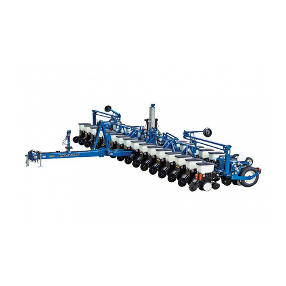
MODEL 3600
TWIN-LINE
OPERATOR & PARTS
MANUAL
M0167
Model: 3600 Twin-Line
Serial Number: 613810 and on
Model Number
Serial Number
Date Purchased
®
Dealer when ordering
®
logo, Twin-Line
®
and Interplant
®
PLANTER
Rev. 3/05
®
Planters
3600
76746-3b
®
are registered trademarks of KINZE Manufacturing, Inc.
Rev. 3/05
Advertisement
Chapters
Table of Contents

Related Manuals for Kinze TWIN-LINE 3600


Summary of Contents for Kinze TWIN-LINE 3600
- Page 1 Always provide the model number and ® serial number to your KINZE Dealer when ordering parts or anytime correspondence is made with KINZE Manufacturing, Inc. KINZE ® , the KINZE ®...
- Page 3 PREDELIVERY/DELIVERY CHECKLIST TO THE DEALER Predelivery service includes assembly, lubrication, adjustment and test. This service helps to ensure that the planter will be delivered to the customer ready for field use. PREDELIVERY CHECKLIST After the planter has been completely assembled, use the following checklist and inspect the planter. Check off each item as it is found satisfactory or after proper adjustment is made.
- Page 4 Check to be sure safety/warning lights are working properly. (Signature Of Follow-Up Person/Dealer Name/Date) ® RETURN THIS COMPLETED FORM TO KINZE IMMEDIATELY, along with Warranty And Delivery Report. Retain photocopy of this form at dealership for After Delivery Check. Tear Along Perforation...
- Page 5 TABLE OF CONTENTS TO THE OWNER ......................1-1 WARRANTY ........................1-2 INTRODUCTION ......................2-1 SPECIFICATIONS ......................3-1 SAFETY PRECAUTIONS ....................4-1 SAFETY WARNING SIGNS ..................... 5-1 MACHINE OPERATION Auxiliary Hydraulic Option ....................6-75 Checking Granular Chemical Application Rate ............... 6-93 Checking Seed Population ....................6-92 Contact Drive Wheel Spring Adjustment ................
- Page 6 TABLE OF CONTENTS ROW UNIT OPERATION (Continued) Seed Hopper ........................7-7 Seed Meter Drive Adjustment .................... 7-8 Seed Meter Drive Release ....................7-7 Spring Tooth Incorporator ....................7-20 “V” Closing Wheel Adjustment (Rubber And Cast Iron) ........... 7-1 LUBRICATION Bushings ..........................8-4 Center Post ........................
- Page 7 TO THE OWNER ® KINZE Manufacturing, Inc. would like to thank you for your patronage. We appreciate your confidence in KINZE farm ® machinery. Your KINZE planter has been carefully designed to provide dependable operation in return for your investment.
- Page 8 Warranty And Delivery Report form must be completed by the KINZE Dealer and signed by the retail purchaser, with copies to the Dealer, to the retail purchaser and to KINZE Manufacturing, Inc. Registration must be completed and sent to KINZE Manufacturing, Inc. within 30 days of delivery of the KINZE ®...
- Page 9 GENERAL INFORMATION D062991118 The information used in this manual was current at the time of printing. However, due to KINZE’s continual attempts to improve its product, production changes may cause your machine to appear slightly different in detail. KINZE Manufacturing, Inc. reserves the right to...
- Page 10 INTRODUCTION 6/99...
- Page 11 • Point Row Clutch Package - Allows half width planting. (Std. 12/16 row, Optional 8 row) • Two-Speed Point Row Clutch Package - Allows half width planting and reduced rate planting ® (Available through KINZE Repair Parts) • Interplant ®...
- Page 12 * Base Machine weights include planter frame, row markers, drive components, tires and wheels, hydraulic cylinders ® and hoses, 12VDC control console, KINZE pull row units (closing wheel arms less closing wheels), seed hopper and lid, dual quick-adjustable down force springs, transport safety chain and point row clutches (12 row and larger sizes).
- Page 13 SAFETY PRECAUTIONS Use a tractor equipped with a roll-over- Safe and careful operation of the tractor and planter protective-system and fasten your seat belt at all times will contribute significantly to the prevention prior to starting the engine. of accidents. Before operating the planter for the first time Since a large portion of farm accidents occur as a result and periodically thereafter, check to be sure...
- Page 14 SAFETY PRECAUTIONS Always install tongue safety pin, manual This machine has been designed and built safety lockup device and transport latch with your safety in mind. Do not make any locking pin before transporting planter. alterations or changes to this machine. Any alteration to the design or construction D060299102 may create safety hazards.
- Page 15 SAFETY PRECAUTIONS Always keep the tractor in gear to provide engine braking when going downhill. Do not coast. Avoid sudden uphill turns on steep slopes. Be a safe and courteous driver. Always yield to oncoming traffic in all situations, including narrow bridges, intersections, etc. Rim and tire servicing can be dangerous.
- Page 16 SAFETY PRECAUTIONS 6/99...
- Page 17 SAFETY WARNING SIGNS The “WARNING” signs illustrated on these pages are placed on the machine to warn of hazards. The warnings found on these signs are for your personal safety and the safety of those around you. OBSERVE THESE WARNINGS! •...
- Page 18 SAFETY WARNING SIGNS D060299127a Part No. G7100-83 (Qty. 2 - One Per Marker) Part No. G7100-42 (Qty. 4 - Two Per Marker) 76746-3b Part No. G7100-75 (Qty. 4 - Front And Rear/Left And Right) D092702101a Part No. G7100-302 (Qty. 1) Rev.
- Page 19 SAFETY WARNING SIGNS D060299104 Part No. G7100-90 (Qty. 1) Part No. G7100-46 (Qty. 1) D08169904 Part No. G7100-68 (Qty. 2 - Front And Rear) Part No. G7100-200 (Qty. 2 - Front And Rear) Rev. 7/04...
- Page 20 SAFETY WARNING SIGNS D060299204 Part No. G7200-03 Red Reflector (Qty. 2) (If Applicable) Part No. G7200-03 Red Reflector (Qty. 2 - Located On Outside Two Transport Tire Scrapers) (If Applicable) D06189903 Part No. G7200-04 Amber Reflector (Qty. 2 - Located At Each End Of Front Axle) (If Applicable) D060299108 Part No.
- Page 21 SAFETY WARNING SIGNS Part No. G7100-68 (Qty. 1) Part No. G7100-63 (Qty. 1) D020501108 Part No. GD2199 (Qty. 1) Part No. G7100-89 (Qty. 2 - Located On Wheel Module On Both Ends Of Planter) D0205001102 Part No. G7100-68 (Qty. 1) Part No.
- Page 22 SAFETY WARNING SIGNS (PLTR132f) 12 Row 30" Shown D060800114 Part No. G7100-262 Amber Reflective Decal (Located On The Hopper Support On Every Other Row Begin- ning On The 1st Row On The L.H. End Of The Planter - Side-Facing In Transport Position) (Standard) (If Applicable) D062300102 Part No.
- Page 23 SAFETY WARNING SIGNS (PLTR132f/TWL173a) 12 Row 30" Shown D060800115a Part No. G7100-258 Red Reflective Decal (Qty. 1 Per Outer Scraper - Located On Top) (If Applicable) Part No. G7100-260 Orange Reflective Decal (Qty. 1 Per Outer Scraper - Located On Bottom) (If Applicable) Part No.
- Page 24 SAFETY WARNING SIGNS (TWL174b/RU120e/RU130d/PLTR132f) Part No. G7100-258 Red Reflective Decal (Qty. 1 - Part No. G7100-258 Red Reflective Decal (Qty. 1 - Located On The Outer Row Unit On the L.H. Side Of Located On The Light Bracket On the L.H. Side Of The Planter - Rear-Facing In Transport Position) The Planter - Rear-Facing In Transport Position) (If Applicable)
- Page 25 SAFETY WARNING SIGNS (TGWL175/TWL177/TWL176) Part No. G7100-259 Amber Reflective Decal (Qty. 2 - 1 Located On Each Side Of Hitch) 8 Row 36"/38" - “T” Hitch (If Applicable) Part No. G7100-259 Amber Reflective Decal (Qty. 2 - 1 Located On Each Side Of Transport Latch Post) 8 Row 36"/38"...
- Page 26 SAFETY WARNING SIGNS (PLTR159/TWL122m/PLTR133f) Part No. G7100-258 Red Reflective Decal (Qty. 1) Part No. G7100-260 Orange Reflective Decal (Qty. 1) (Located On The L.H. End Of The Planter - Rear-Facing In Transport Position) (If Applicable) ® WITH INTERPLANT D020101103 PACKAGE OPTION Part No.
- Page 27 SAFETY WARNING SIGNS D06039901 Part No. G7100-115 (1 Per Row Unit - Located On Underside Of Optional Granular Chemical Hopper Lid) D020101105 ® Part No. G7100-249 (Qty. 1 - Interplant Push Row Unit Lift Lever) 5-11 Rev. 9/02...
- Page 28 SAFETY WARNING SIGNS 5-12 Rev. 5/01...
- Page 29 MACHINE OPERATION The following information is general in nature and was The control console operates on 12 volt DC only. If written to aid the operator in preparation of the tractor two 12 volt batteries are connected in series, and planter for use, and to provide general operating ALWAYS make power connection on battery which procedures.
- Page 30 MACHINE OPERATION LEVELING THE PLANTER (RU113) For proper operation of the planter and row units, it is important that the planter frame and row unit parallel arms be approximately level. The toolbar should oper- ate at a 20-22" height, measured to the bottom of the toolbar.
- Page 31 MACHINE OPERATION TIRE PRESSURE NOTE: On planters equipped with push row units and no till coulters, the uplift from the down pres- D020501108 sure springs may cause the wings to rise slightly in planting position. The problem is compounded if static pressure is trapped in the planter’s hydraulic lift system causing the wing cylinders to extend slightly.
- Page 32 MACHINE OPERATION SEED RATE TRANSMISSION STANDARD RATE DRIVE ADJUSTMENT D020501108 Planting population rate changes are made at each end of the planter. The seed rate transmission is designed to allow simple, rapid changes in sprockets to obtain the desired planting population. By removing the lynch pins on the hexagon shafts, sprockets can be interchanged with those from the sprocket storage rod bolted to the wheel module on each side of the planter.
- Page 33 MACHINE OPERATION WRAP SPRING WRENCH OPERATION RIDGE PLANTING If the chain idler is equipped with a wrap spring wrench, When ridge planting, the drive wheels and transport chain tension is released and/or added as shown below. wheels can be lowered 2" or 4" to the lower mounting holes in the wheel arms to increase the planter toolbar To release chain tension, rotate the knurled collar on the height.
- Page 34 MACHINE OPERATION SHEAR PROTECTION HYDRAULIC/ELECTRIC OPERATION 76746-24 The planter driveline, row unit and fertilizer compo- nents are protected from damage by shear pins. If excessive load should cause a pin to shear, it is important to determine where binding has occurred before replacing the pin.
- Page 35 MACHINE OPERATION The raise/wing lock and rotate/tongue (fold function) TRANSPORT TO FIELD SEQUENCE switches are MOMENTARY ON-OFF-MOMENTARY ON type and must be held in position while operating Position the planter in a relatively flat open area. Try to the tractor hydraulic lever. Activating a fold function avoid an area with furrows, etc.
- Page 36 MACHINE OPERATION D062501101 3. Remove the manual safety lockup from under the front center lift cylinder and place it in the storage location on the left side of the planter axle. D060299107 Transport Position Tongue Safety Pin - In Storage Position 2.
- Page 37 MACHINE OPERATION 7. Hold the control console switch labeled RAISE/ D061901120 WING LOCK in WING LOCK and operate the hydraulic lever to release the wing locks. D061901108 5. Raise the planter 1-2". The safety hook will release and snap away from the catch pin on the top of the pivot post.
- Page 38 MACHINE OPERATION FIELD OPERATION FIELD TO TRANSPORT SEQUENCE There are two raised positions on the planter. One is Position the planter in a relatively flat area. Try to avoid the RAISED FIELD POSITION which is when the an area with furrows, etc. planter wing cylinders are fully extended and the center lift cylinders are at mid-stroke.
- Page 39 MACHINE OPERATION 5. Hold the control console switch labeled RAISE/ 3. Hold the control console switch labeled ROTATE/ WING LOCK in RAISE and operate the hydraulic TONGUE in TONGUE and operate the hydraulic lever until the two center lift cylinders are fully lever until the tongue is fully extended.
- Page 40 MACHINE OPERATION 9. Install transport latch locking pin. D060299106 10. Remove manual safety bar from its storage loca- tion on the left side of the axle assembly and position it behind the front center lift cylinder. D06189903 Storage Position D060299107 Transport Position WARNING: Always install the manual safety lockup prior to working under the planter or...
- Page 41 MACHINE OPERATION Two solenoid valves, located on the valve block on the ROW MARKER OPERATION rear R.H. side of the center frame, and a three position 76740-28 selector switch on the control console permit the opera- tor to lower or raise the desired row marker. Solenoid Valves See “Row Marker Speed Adjustment”.
- Page 42 A notched marker disc blade, for use in more severe no DANGER: To avoid serious injury or death, till conditions, is available from KINZE ® through your care must be taken when operating row KINZE ®...
- Page 43 MACHINE OPERATION When using the even-row push row unit option, adjust NOTE: If tractor hitch is offset 7 " to the right of the marker extensions as shown below. center line of the tractor, add 7 " to the marker dimension on the R.H.
- Page 44 KPM I MACHINE OPERATION KPM I ELECTRONIC SEED MONITOR Monitor Key Functions ..........6-16 LCD Functions ............6-16 Changing The Audible Alarm Volume ....6-17 (MTR28) Warnings And Alarms ..........6-17 Replacing A Faulty Sensor ........6-18 Field Operation ............6-19 Programming/Connecting Seed Tubes ....
- Page 45 KPM I MACHINE OPERATION WARNINGS AND ALARMS EXAMPLE: The system is setup to display rear/front sections. Press SELECT key. 1. System Alarms - A system alarm is activated The FRONT icon will be flashing and the when the monitor detects a faulty sensor or one of REAR section will be displayed on the bar several other communication faults.
- Page 46 KPM I MACHINE OPERATION 7. Seed Counting Sensor Too Dirty Warning - NOTE: This warning will not trigger unless a minimum time of continuous planting has passed. After the seed counting sensors end their internal self-calibration, the monitor may detect one or more sensors are either too dirty or blocked.
- Page 47 MACHINE OPERATION KPM I FIELD OPERATION PROGRAMMING/CONNECTING SEED TUBES (MTR28e/MTR28c/MTR28d/MTR28b) STEP 1 All the seed tubes w/sensors must be disconnected from the harness and the Press the ON/OFF key to turn the monitor monitor must be off. on and off. STEP 2 Press the ON key.
- Page 48 KPM I MACHINE OPERATION STEP 4 Press and hold the OK key to confirm the STEP 5 Plug each seed tube w/sensor into the selection and continue holding until the row harness in a predetermined order. Row 1 numbers appear on the display. During first, row 2 second and so on up to 18 rows.
- Page 49 KPM I MACHINE OPERATION STEP 7 If this condition is satisfied, press and hold STEP 8 Follow STEPS 5 through 7 to install the the OK key to save the setup for the current second section. If no seed tubes are installed on the second section, press and hold the section.
-
Page 50: Table Of Contents
KPM II MACHINE OPERATION KPM II ELECTRONIC SEED MONITOR Seed flow for up to 36 rows, in two 18 row sections (left/ right or rear/front), may be monitored with one monitor. (MTR29) For less complicated applications(18 rows or less), all rows may be programmed in one section and the other left disabled. -
Page 51: Monitor Key Functions
KPM II MACHINE OPERATION MONITOR KEY FUNCTIONS SEED POPULATION/SEED SPACING • Immediately displays average seed Push keys allow the user to select or change the POPULATION and the average seed SPACING of all operating mode, the active displays or the current active rows. -
Page 52: Upper Lcd Functions
MACHINE OPERATION KPM II When the front section is disabled, the UPPER LCD FUNCTIONS row spacing will automatically double to (MTR29H) maintain the proper implement width in the monitor. A 23 row 15" configuration changes to a 12 row 30" configuration with a touch of the SELECT key. -
Page 53: Lower Lcd Functions
MACHINE OPERATION KPM II LOWER LCD FUNCTIONS ROW SPACING Press the arrow keys to ROW SPACING to display the current spacing between rows in inches or centimeters. (MTR29g) The ROW SPACING icons turn on, displaying a 3 digit, one decimal place format. In the area count mode, this function displays the implement width in feet or meters, using a 3 digit, no decimal places format. - Page 54 MACHINE OPERATION KPM II SEED POPULATION/SEED SPACING FIELD AREA/TOTAL AREA Each AREA FIELD/TOTAL key press alternates Each SEED POP/SPACING key press alternates between field area and total area. between seed population and seed spacing. Field area displays the total number of acres or hectares Seed population displays the average number of seeds using a 6 digit, one decimal place format.
- Page 55 KPM II MACHINE OPERATION STEP 4 To exit without saving, press and release the PROGRAMMING - Changing The Audible Alarm Volume OK key. The monitor will restore the lower LCD to show the setting of the item, and the arrow icon will flash, allowing the user to STEP 1 To enter the programming mode, press and select another item to program.
- Page 56 KPM II MACHINE OPERATION PROGRAMMING - Row Spacing PROGRAMMING - Units (Metric Or English) STEP 1 To enter the programming mode, press and STEP 1 Prior to entering the programming mode, hold the SETUP key. The monitor will emit the application mode (rear/front or left/right) must be active.
- Page 57 KPM II MACHINE OPERATION NOTE: The monitor limits the entry of row spacing to a minimum of 10.0 inches (25.4 cm) and to a maximum of 99.9 inches (253.7 cm). If the monitor is configured to a rear/front configuration, the limits change to a minimum of 5.0 inches (12.7 cm) and a maximum of 49.9 inches (126.8 cm).
- Page 58 KPM II MACHINE OPERATION PROGRAMMING - Speed • In field conditions, measure 330 feet ( mile) or 100 meters, depending on the unit of STEP 1 To enter the programming mode, press and measurement selected. hold the SETUP key. The monitor will emit several short beeps, followed by a long •...
-
Page 59: Clearing Total Area
KPM II MACHINE OPERATION NOTE: If a discrepancy occurs and digits must be changed, follow STEPS 1 and 2 to enter the programming mode and proceed as follows: •Press the OK key and the flashing arrow becomes solid. The least significant digit of the displayed value will be blinking. -
Page 60: Area Counter/Speedometer Mode
KPM II MACHINE OPERATION AREA COUNTER/SPEEDOMETER MODE The three possible data communication bus errors are: If the monitor is installed with only a radar distance sensor (no seed tubes attached), the monitor becomes LCD Display Error Condition a speedometer. If (a) the monitor is connected to a SYS HI The data communication radar distance sensor, (b) the signal cable from the... -
Page 61: Replacing A Faulty Sensor
KPM II MACHINE OPERATION 4. Section Not Selected Warning - If the monitor REPLACING A FAULTY SENSOR was programmed for two sections and only one is currently selected for display (by pressing the To replace a faulty sensor; (a) disconnect the faulty SELECT key), the icon of the disabled section will sensor and check the monitor to be sure the correct flash for a period of 1 minute, then turn off at each... -
Page 62: Clearing Field Area
KPM II MACHINE OPERATION CLEARING FIELD AREA (MTR29g/MTR29b/MTR29a/MTR29c/MTR29f/MTR29c/MTR29f) (MTR29n/MTR28b) To reset the counter, press the UP or DOWN arrow keys to move the arrow in the lower display to FIELD AREA. Press the UP and DOWN arrow keys at the same time and hold them down for a short period of time to clear the data. -
Page 63: Programming/Connecting Seed Tubes, Radar/Magnetic Distance Sensors And/Or Shaft Rotation Sensors
KPM II MACHINE OPERATION 01139923 PROGRAMMING/CONNECTING SEED TUBES, RADAR/MAGNETIC DISTANCE SENSORS AND/OR SHAFT ROTATION SENSORS KPM II ® STEP 1 All sensors (including the seed tubes w/ sensors, radar, magnetic distance and shaft rotation sensors) must be unplugged from the harness and/or console and the monitor Flashing must be off. - Page 64 KPM II MACHINE OPERATION 01139922 STEP 4 Press and hold the OK key to confirm selection. The upper display will alternate KPM II between “NEW” and “SYS?”. ® The alarm will sound four short beeps followed by one long beep. At this point your selection has been saved and row numbers will appear flashing on the upper display.
- Page 65 KPM II MACHINE OPERATION 01139921 STEP 5 Determine which row you want as number one and plug the seed tube w/sensor into the KPM II harness. ® Continue plugging in sensors along with shaft rotation sensors if so equipped. Row 1 first, row 2 second and so on up to 18 rows.
- Page 66 KPM II MACHINE OPERATION STEP 6 If the monitor system includes shaft rotation 01139919 sensors, these can be installed at any time as the seed tubes are connected. The first shaft KPM II ® rotation sensor installed will be assigned to the rows on the L.H.
- Page 67 KPM II MACHINE OPERATION 01139914 STEP 7 When all the seed tubes for the current section (Rear/Front or Left/Right) are KPM II ® installed, check to be sure the monitor displays solid numbers for the number of seed tubes connected. Press and hold the OK key to save the setup for the current section.
- Page 68 KPM II MACHINE OPERATION 01139912 STEP 8 Follow STEPS 5 through 7 to install the KPM II second section. If no seed tubes are installed ® on the second section, press and hold the OK key. The word “DONE” will appear on upper display.
- Page 69 KPM II MACHINE OPERATION 01139910 STEP 8 (Continued) KPM II ® Rows Installed FLASHING (1213 14 15 16 17 18) SETUP FRONT SAVE? Row Waiting To SCAN Be Connected SEED POPULA TION SPACING SEED UNITS SPACING FIELD SPEED AREA FRONT TOTAL VOLUME SETUP...
- Page 70 KPM II MACHINE OPERATION STEP 9 With the lower display showing “GNDSPD”, connect the distance sensor. The monitor NOTE: To reprogram the system to monitor more will display “PICKUP” if a magnetic distance or less rows (up to the maximum of 18 per section, sensor is connected or “RADAR”...
-
Page 71: Row-By-Row Alarm Level Setting
MACHINE OPERATION KPM II STACK-MODE STEP 3 Press the OK key. Row number starts flashing. ROW-BY-ROW ALARM LEVEL SETTING (Requires Version V0.06 Or Higher Software - STEP 4 Arrow UP or DOWN to desired row. KPM II Monitors Only) This feature allows the audio alarm to be disabled on STEP 5 Press SELECT key. - Page 72 MACHINE OPERATION KPM II STACK-MODE KPM II STACK-MODE ELECTRONIC The SMM console is available as a separate package for ® use when 3600 planters are equipped with Interplant SEED MONITOR Package rows. (MTR41e) The monitor system is powered by the tractor battery (requires 12 volts DC).
-
Page 73: Monitor Key Functions
MACHINE OPERATION KPM II STACK-MODE MONITOR KEY FUNCTIONS SEED POPULATION/SEED SPACING Push keys allow the user to select or change the • Immediately displays the average seed POPULATION operating mode, the active displays or the current and the average seed SPACING of all active rows. configuration. -
Page 74: Upper Lcd Functions
MACHINE OPERATION KPM II STACK-MODE STEP 1 Press SELECT key once to show one section. UPPER LCD FUNCTIONS The flashing icon shows the section that is (MTR29h) not selected. The selected section icon is continuously displayed on the LCD. EXAMPLE: The system is setup to display rear section on KPM II Stack-Mode console and front section on SMM console. -
Page 75: Lower Lcd Functions
MACHINE OPERATION KPM II STACK-MODE LOWER LCD FUNCTIONS ROW SPACING Press the arrow keys to ROW SPACING to display the current spacing between rows in inches or centimeters. (MTR29g) The ROW SPACING icons turn on, displaying a 3 digit, one decimal place format. In the area count mode, this function displays the implement width in feet or meters, using a 3 digit, no decimal places format. - Page 76 MACHINE OPERATION KPM II STACK-MODE SEED POPULATION/SEED SPACING FIELD AREA/TOTAL AREA Each AREA FIELD/TOTAL key press alternates Each SEED POP/SPACING key press alternates between field area and total area. between seed population and seed spacing. Field area displays the total number of acres or hectares Seed population displays the average number of seeds using a 6 digit, one decimal place format.
- Page 77 MACHINE OPERATION KPM II STACK-MODE STEP 4 To exit without saving, press and release the PROGRAMMING - Changing The Audible Alarm Volume OK key. The monitor will restore the lower LCD to show the setting of the item, and the arrow icon will flash, allowing the user to STEP 1 To enter the programming mode, press and select another item to program.
- Page 78 MACHINE OPERATION KPM II STACK-MODE PROGRAMMING - Row Spacing PROGRAMMING - Units (Metric Or English) STEP 1 To enter the programming mode, press and STEP 1 Prior to entering the programming mode, hold the SETUP key. The monitor will emit the application mode (rear/front, left/right or four sections) must be active.
- Page 79 MACHINE OPERATION KPM II STACK-MODE NOTE: The monitor limits the entry of row spacing to a minimum of 10.0 inches (25.4 cm) and to a maximum of 99.9 inches (253.7 cm). If the monitor is configured to a rear/front configuration, the limits change to a minimum of 5.0 inches (12.7 cm) and a maximum of 49.9 inches (126.8 cm).
- Page 80 MACHINE OPERATION KPM II STACK-MODE PROGRAMMING - Speed • In field conditions, measure 330 feet ( mile) or 100 meters, depending on the unit of STEP 1 To enter the programming mode, press and measurement selected. hold the SETUP key. The monitor will emit several short beeps, followed by a long •...
-
Page 81: Clearing Total Area
MACHINE OPERATION KPM II STACK-MODE NOTE: If a discrepancy occurs and digits must be changed, follow STEPS 1 and 2 to enter the programming mode and proceed as follows: •Press the OK key and the flashing arrow becomes solid. The least significant digit of the displayed value will be blinking. -
Page 82: Area Counter/Speedometer Mode
MACHINE OPERATION KPM II STACK-MODE AREA COUNTER/SPEEDOMETER MODE The four possible data communication bus errors are: If the monitor is installed with only a radar distance sensor (no seed tubes attached), the monitor becomes LCD Display Error Condition a speedometer. If (a) the monitor is connected to a SYS HI The data communication radar distance sensor, (b) the signal cable from the... -
Page 83: Replacing A Faulty Sensor
MACHINE OPERATION KPM II STACK-MODE 4. Section Not Selected Warning - If the monitor REPLACING A FAULTY SENSOR was programmed for two sections and only one is currently selected for display (by pressing the NOTE: Stack-Mode Seed Sensors are identified by SELECT key), the icon of the disabled section will a blue 3-pin connector. -
Page 84: Field Operation
MACHINE OPERATION KPM II STACK-MODE At power up, the lower LCD will show speed (MPH or FIELD OPERATION KM/H). Press the ON/OFF key to turn the monitor (MTR29g/MTR29b/MTR29a/MTR29c/MTR29f/MTR29c/MTR29f) Information regarding each section is dis- (MTR28e) played alternately every 5 seconds. REAR/FRONT CONFIGURATION (Without SMM Console Installed) •... -
Page 85: Clearing Field Area
MACHINE OPERATION KPM II STACK-MODE CLEARING FIELD AREA (MTR29n/MTR28b) To reset the counter, press the UP or DOWN arrow keys to move the arrow in the lower display to FIELD AREA. Press the UP and DOWN arrow keys at the same time and hold them down for a short period of time to clear the data. -
Page 86: Programming/Connecting Smm Console, Shaft Rotation Sensors, Seed Tubes And/Or Radar/Magnetic Distance Sensors
MACHINE OPERATION KPM II STACK-MODE STEP 3 The monitor automatically defaults to rear/ PROGRAMMING/CONNECTING SMM CONSOLE, front. Press the SELECT key once for left/ SHAFT ROTATION SENSORS, SEED TUBES AND/ right and twice for four sections (front right/ OR RADAR/MAGNETIC DISTANCE SENSORS front left/rear right/rear left). - Page 87 MACHINE OPERATION KPM II STACK-MODE 12060211 STEP 4 Press and hold the OK key to confirm selection. The upper display will alternate ® between “NEW” and “SYS?”. The alarm will sound four short beeps followed by one long beep. At this point your selection has been saved and row numbers will appear flashing on the upper display of the KPM II.
- Page 88 MACHINE OPERATION KPM II STACK-MODE STEP 5 (If Applicable) Connect SMM console into NOTE: Illustrated using rear/front configuration. junction Y-harness which was installed The KPM II Stack-Mode console shows LEFT in the between the KPM II Stack-Mode console and left/right configuration, REAR in the rear/front the primary harness.
- Page 89 MACHINE OPERATION KPM II STACK-MODE STEP 6 If the monitor system includes shaft rotation 12060211 sensors, these should be installed at this time. Plug in the L.H. shaft first, then the R.H. ® shaft. L.H. and R.H. is determined by facing in the direction the machine will travel when in use.
- Page 90 MACHINE OPERATION KPM II STACK-MODE STEP 6 (Continued) STEP 7 Determine which row you want as number one and plug the seed tube w/sensor into the 12060211 harness. ® Continue plugging in sensors along with shaft rotation sensors if so equipped. Row 1 first, row 2 second and so on up to 18 rows.
- Page 91 MACHINE OPERATION KPM II STACK-MODE STEP 7 (Continued) 12060211 ® • KPM II ® Row Installed FLASHING 13 14 15 16 17 18) (FRONT) SETUP REAR Row Waiting To SCAN Be Connected SEED POPULATION SPACING SEED UNITS SPACING FIELD SPEED REAR AREA SETUP...
- Page 92 MACHINE OPERATION KPM II STACK-MODE 12060211 STEP 8 When all the seed tubes for the current section (rear/front, left/right or four section) are ® installed, check to be sure the upper LCD on the KPM II Stack-Mode console displays solid numbers for the number of seed tubes connected.
- Page 93 MACHINE OPERATION KPM II STACK-MODE STEP 8 (Continued) 12060211 ® • KPM II ® SETUP FRONT REAR SCAN SEED POPULATION SPACING SEED UNITS SPACING FIELD SPEED REAR AREA SETUP TOTAL VOLUME AREA AREA SEED FIELD POP. SELECT SPEED SCAN TOTAL SPACING CLEAR SETUP...
- Page 94 MACHINE OPERATION KPM II STACK-MODE 12060212 STEP 9 Follow STEPS 6, 7 and 8 to install the second section. If no seed tubes are installed on the ® second section, press and hold the OK key. The word “DONE” will appear on upper display. The alarm will sound four short beeps followed by one long beep and the SAVE? icon turns off.
- Page 95 MACHINE OPERATION KPM II STACK-MODE STEP 9 (Continued) 12060214 12060213 ® ® • • KPM II KPM II ® ® Row Installed Rows Installed FLASHING FLASHING 13 14 15 16 17 18) (12 13 14 15 16 17 18) FRONT SETUP SETUP FRONT...
- Page 96 MACHINE OPERATION KPM II STACK-MODE STEP 9 (Continued) STEP 10 With the lower display showing “GNDSPD”, connect the distance sensor. The monitor 12060215 will display “PICKUP” if a magnetic distance sensor is connected or “RADAR” if a radar ® distance sensor is installed. Only one distance sensor can be connected at a time.
- Page 97 MACHINE OPERATION KPM II STACK-MODE STEP 10 (Continued) NOTE: To reprogram the system to monitor more or 12060216 less rows (up to the maximum of 18 per section, 72 total in four section configuration), all sensors must ® be unplugged, followed by the complete setup procedure.
-
Page 98: Row-By-Row Alarm Level Setting
MACHINE OPERATION KPM II STACK-MODE 12060218 ROW-BY-ROW ALARM LEVEL SETTING (Requires Version V2.05 Or Higher Software - ® KPM II Stack-Mode Monitors Only) This feature allows the audio alarm to be disabled on selected rows in applications such as planting seed corn. NOTE: The system should be programmed to monitor all planter rows prior to performing these steps. - Page 99 MACHINE OPERATION KPM II STACK-MODE STEP 3 Press the OK key. Row number starts flashing. STEP 4 Arrow UP or DOWN to desired row. STEP 5 Press SELECT key. “AVG” starts flashing. STEP 6 Arrow UP or DOWN to choose one of the following options.
- Page 100 MACHINE OPERATION KPM II STACK-MODE POINT ROW CLUTCHES PRC019(PLTR48) Stop Wrap Input (Standard on 12 and 16 Row/Optional on 8 Row) Output Collar Spring 76740-2 Control Tang The point row clutch consists of a wrap spring riding on an input hub and an output hub. During operation the wrap spring is wrapped tightly over the hubs connecting them in a positive engagement.
- Page 101 MACHINE OPERATION TWO-SPEED POINT ROW CLUTCHES The ratio of population reduction is determined by the sprocket ratio between the drive and driven sprockets 81826-8 on the wheel module extension. A rate reduction decal like the one shown below is located on the wheel module extension.
- Page 102 MACHINE OPERATION ROCK GUARDS EVEN-ROW PUSH ROW UNIT (PLTR49a) (PLTR132g) Transport wheel rock guards are designed for use on both sides of each of the four center transport wheels when the planter is used in rocky conditions. Rock guards will help prevent rocks, which can cause damage to the row units, from being picked up by the wheels.
- Page 103 MACHINE OPERATION NOTE: Be sure row markers are in transport position AUXILIARY HYDRAULIC OPTION and all pressure is removed from the hydraulic sys- tem. A customer-supplied auxiliary hydraulic option may be added to provide 10 GPM of oil flow at the rear of the Remove the cover from the valve block, located on planter.
- Page 104 MACHINE OPERATION DOUBLE DISC FERTILIZER OPENER D06259919 Pin Storage Position The double disc fertilizer openers should be posi- tioned during assembly to place fertilizer no closer than 2" to either side of the row. If the planter frame is level and at proper 20" operating height, fertilizer depth will be approximately 4".
- Page 105 MACHINE OPERATION NOTCHED SINGLE DISC FERTILIZER Adjust drop tube on each row using the slotted mount- ing holes in the drop tube. Adjust drop tube so it is OPENER - STYLE A protected by the knife/scraper from soil contact and wear.
- Page 106 MACHINE OPERATION NOTCHED SINGLE DISC FERTILIZER Using the slotted mounting holes in the drop tube mount, adjust fertilizer drop tube behind the knife so it is OPENER - STYLE B protected from soil contact and wear. The liquid drop tube should be adjusted "...
- Page 107 MACHINE OPERATION RESIDUE WHEEL ATTACHMENT FOR DEPTH/GAUGE WHEEL ATTACHMENT NOTCHED SINGLE DISC FERTILIZER FOR NOTCHED SINGLE DISC FERTILIZER OPENER OPENER (For Use With STYLE B Notched Single Disc (For Use With STYLE B Notched Single Disc Fertilizer Opener) Fertilizer Opener) D052201104 D061101202a The depth/gauge wheel attachment for the notched...
- Page 108 MACHINE OPERATION HD SINGLE DISC FERTILIZER OPENER Fertilizer opener down pressure can be adjusted from 250 lbs. to 640 lbs. To make down pressure adjust- ments, raise planter to remove weight from the fertilizer D062601103 opener and turn spring preset nut clockwise to increase down pressure and counterclockwise to decrease down pressure.
- Page 109 MACHINE OPERATION STEP 3 Raise spring to clear blade assembly and Maintain liquid fertilizer drop tube/scraper adjust- at the same time raise blade assembly until ment as shown below. storage strap can be positioned onto lockup (INS16a) pin and install hair pin clip. STEP 4 Reinstall depth adjustment nut and tighten.
- Page 110 MACHINE OPERATION DRY FERTILIZER ATTACHMENT (PLTR7) D061901101 Shown with augers positioned for low rate delivery (PLTR6) Shown with augers positioned for high rate delivery Remove " stainless steel cap screws holding augers in place on shaft and reposition augers to change Shown With HD Single Disc Fertilizer Openers delivery rate.
- Page 111 MACHINE OPERATION IMPORTANT: Certain analysis of fertilizer, if placed At the end of the planting season, or when the fertilizer too close to the seed, may cause germination or attachment is not going to be used for a period of time, seedling damage especially if used in amounts in the hoppers should be disassembled, cleaned and excess of fertilizer manufacturer’s recommenda-...
- Page 112 MACHINE OPERATION LIQUID FERTILIZER ATTACHMENT OPTIONAL SQUEEZE PUMP On machines equipped with the squeeze pump option, NOTE: An optional low rate check (FRTZ208) the rate of liquid fertilizer application is determined by valve is available for installation the combination of sprockets on the squeeze pump in-line between the liquid fertil- drive and driven shafts.
- Page 113 MACHINE OPERATION If either of the end pump hoses should run off the back 81689-16 plate, loosen the hose clamps on the intake manifold and rotate the hose as follows. 48931-2 Clockwise Counter Clockwise Discharge Manifold Rearward 81689-19 Hose Clamp For the right hand hose (facing the pump from front as shown above) twist the hose turn in the clockwise...
- Page 114 MACHINE OPERATION OPTIONAL PISTON PUMP PISTON PUMP CONTACT DRIVE WHEEL SPRING ADJUSTMENT - STYLE A D07250004 (A8482a) 1" If the machine is equipped with the piston pump option, the rate of liquid fertilizer application is determined by the piston pump settings. The initial spring tension, on the down pressure spring(s) on the piston pump contact drive wheel, is set leaving 1"...
- Page 115 MACHINE OPERATION PISTON PUMP GROUND DRIVE WHEEL SPRING CLEANING ADJUSTMENT - STYLE B The tanks and all hoses are made of sturdy plastic and Initial spring tension on the down pressure spring, on the rubber to resist corrosion. However, the tanks, hoses piston pump ground drive wheel, is set leaving 12 "...
- Page 116 MACHINE OPERATION IMPORTANT: The rear trailer hitch is designed for REAR TRAILER HITCH use with piston pump only. Maximum allowable D07309901a hitch weight is 200 lbs. Gross towing weight should not exceed 6000 lbs. or the equivalent of a loaded 500 gallon tank and running gear.
- Page 117 MACHINE OPERATION MANUAL SAFETY LOCKUP ROW MARKER SAFETY LOCKUP Never allow anyone to work around or under the Install safety lockup devices over marker cylinder rods planter without first securing the manual safety lockup when transporting the planter or working around the in the locked position.
- Page 118 MACHINE OPERATION TRANSPORT LATCH LOCKING PIN TONGUE SAFETY PIN The transport latch locking pin when installed will The tongue safety pin when installed will prevent the prevent the latch bar from disengaging and allowing tongue cylinder from retracting should hydraulic failure the planter frame to swing away.
- Page 119 MACHINE OPERATION TRANSPORTING THE PLANTER PLANTING SPEED WARNING: Always make sure safety/ Planters are designed to operate within a speed range warning lights, reflective decals and SMV of 2 to 8 MPH. See “Planting And Application Rate sign are in place and visible prior to Charts”.
- Page 120 MACHINE OPERATION CHECKING SEED POPULATION 4. Count seeds in measured distance. 5. Multiply the number of seeds placed in of an acre 1. Tie up one or more sets of closing wheels by running 1000 by 1000. This will give you total population. a chain or rubber tarp strap between the hopper support panel and closing wheels.
- Page 121 MACHINE OPERATION Determining Pounds Per Acre D05149901 (Brush-Type Seed Meter) To determine pounds per acre: Seeds Per Seeds Per Pounds ÷ Acre On Pound From Chart Seed Tag Acre On Bag To determine bushels per acre: Pounds Unit Weight Bushels ÷...
- Page 122 MACHINE OPERATION GENERAL PLANTING RATE INFORMATION These planting rate charts are applicable to KINZE ® Model 3600 Twin-Line ® Planters. See “Tire Pressure” for recommended tire pressures. Not all row spacings listed are applicable to all size planters. IMPORTANT: The sprocket combinations listed in these charts are best for average conditions. Changes in sprocket combinations may be required to obtain desired planting population.
- Page 123 MACHINE OPERATION PLANTING RATES FOR FINGER PICKUP SEED METERS (STANDARD DRIVE) APPROXIMATE SEEDS/ACRE FOR VARIOUS ROW WIDTHS Recomm. Average Transmission Speed Seed Sprockets Range Spacing 30" Rows 36" Rows 38" Rows Drive Driven (MPH) In Inches 16,186 13,488 12,778 4 to 6 12.9 16,785 13,988...
- Page 124 MACHINE OPERATION Z214/RH PLANTING RATES FOR BRUSH-TYPE SEED METERS (STANDARD DRIVE) APPROXIMATE SEEDS/ACRE FOR 30"/36"/38" ROW WIDTHS 60 Cell 48 Cell Soybean Or High-Rate Milo/ Specialty Soybean Or High-Rate Transmission Average Average Grain Sorghum Acid-Delinted Cotton Sprockets Seed Seed Speed Spacing Spacing Range...
- Page 125 MACHINE OPERATION Z214/RH PLANTING RATES FOR BRUSH-TYPE SEED METERS (STANDARD DRIVE) APPROXIMATE SEEDS/ACRE FOR 15"/18"/19" ROW WIDTHS 60 Cell 48 Cell Soybean Or High-Rate Milo/ Specialty Soybean Or High-Rate Transmission Average Average Grain Sorghum Acid-Delinted Cotton Sprockets Seed Seed Speed Spacing Spacing Range...
- Page 126 MACHINE OPERATION RH/Z215 PLANTING RATES FOR BRUSH-TYPE SEED METERS (STANDARD DRIVE) APPROXIMATE SEEDS/ACRE FOR VARIOUS ROW WIDTHS 36 Cell 30 Cell Milo/Grain Sorghum Or Transmission Average Average Acid-Delinted Large Cotton Acid-Delinted Cotton Sprockets Seed Seed Speed Spacing Spacing Range 30" Rows 36"...
- Page 127 MACHINE OPERATION PLANTING RATES FOR BRUSH-TYPE SEED METERS (STANDARD DRIVE) APPROXIMATE HILLS/ACRE FOR VARIOUS ROW WIDTHS Due to variations in cotton seed size, meters equipped with 12 cell acid-delinted hill-drop cotton discs will plant from 3 to 6 seeds per cell. Select proper disc for seed size range to be planted. To determine planter transmission setting , determine desired hill spacing and select the transmission ratio closest to the hill spacing in inches on the chart.
- Page 128 MACHINE OPERATION DRY INSECTICIDE APPLICATION RATES APPROXIMATE POUNDS/ACRE AT 5 MPH FOR VARIOUS ROW WIDTHS Meter Setting 30" Rows 36" Rows 38" Rows CLAY GRANULES 10.7 11.4 13.1 10.9 10.3 14.2 11.8 11.2 15.5 12.9 12.3 16.4 13.7 12.9 17.2 14.3 13.6 18.8...
- Page 129 MACHINE OPERATION DRY HERBICIDE APPLICATION RATES APPROXIMATE POUNDS/ACRE AT 5 MPH FOR VARIOUS ROW WIDTHS CLAY GRANULES Meter Setting 30" Rows 36" Rows 38" Rows 10.7 11.6 12.6 10.5 10.0 13.6 11.3 10.7 14.6 12.1 11.5 15.7 13.1 12.4 17.0 14.1 13.4 18.1...
- Page 130 MACHINE OPERATION DRY FERTILIZER APPLICATION RATES APPROXIMATE RATE IN POUNDS PER ACRE Drive Driven Low Rate Position High Rate Position Sprocket Sprocket 30" Rows 36" Rows 38" Rows 30" Rows 36" Rows 38" Rows NOTE: Uneven delivery may result from attempting to use lower rates than indicated by the chart. Direction Of Rotation High Rate Position...
- Page 131 MACHINE OPERATION LIQUID FERTILIZER SQUEEZE PUMP APPLICATION RATES GALLONS PER ACRE 30" 36" 38" 30" 36" 38" Drive Driven Rows Rows Rows Drive Driven Rows Rows Rows 18.7 15.6 14.8 19.9 16.6 15.7 23.7 19.8 18.7 10.4 26.8 22.3 21.1 11.1 31.9 26.6...
- Page 132 MACHINE OPERATION LIQUID FERTILIZER PISTON PUMP APPLICATION RATES GALLONS PER ACRE Applies To Model LM-2455-R Pump With 18 Tooth Sprocket And 4.10" x 6" Contact Drive Tire Pump Setting 8 Row 36" 11.5 17.1 22.9 28.6 34.3 40.0 45.7 51.4 57.1 8 Row 38"...
- Page 133 MACHINE OPERATION LIQUID FERTILIZER PISTON PUMP APPLICATION RATES GALLONS PER ACRE Applies To Model LM-4405 Pump With 18 Tooth Sprocket And 7.60" x 15" Ground Drive Tire Pump Setting 8 Row 36" 13.9 18.5 23.1 27.6 32.0 36.8 41.5 46.1 8 Row 38"...
- Page 134 MACHINE OPERATION 6-106 Rev. 7/04...
- Page 135 ROW UNIT OPERATION PLANTING DEPTH LF212299-15 Planting depth is maintained by the row unit gauge wheels. To increase or decrease the planting depth, first raise the planter to remove weight from the wheels. Lever Then push down on the depth adjustment handle and reposition it forward to decrease depth or rearward to increase planting depth.
- Page 136 ROW UNIT OPERATION COVERING DISCS/SINGLE PRESS The closing wheels can be installed in two locations either “offset” (to improve residue flow) or “directly” WHEEL ADJUSTMENT opposite. If set “directly” opposite, the forward in- stallation holes should be used. WARNING: Raise planter and install safety STYLE B lockup devices before making covering (RU83o)
- Page 137 ROW UNIT OPERATION DRAG CLOSING ATTACHMENT Eccentric bushings in the wheel arm stop allow for lateral adjustment of the covering discs/single press wheel assembly. Using a " wrench, loosen the hardware LF212299-18 which attaches the assembly to the wheel arm stop. Using another "...
- Page 138 ROW UNIT OPERATION FINGER PICKUP SEED METER NOTE: Powdered graphite is recommended for finger pickup seed meter lubrication to ensure Refer to the planting rate chart for recommended seed efficient operation of the mechanism and to extend drive transmission sprocket combinations. the life of its components.
- Page 139 ROW UNIT OPERATION Large milo/grain sorghum: BRUSH-TYPE SEED METER 30 cells to meter seed sizes from D12220403 10,000 to 16,000 seeds per pound (Light blue color-coded). (PLTR17) High-rate small milo/grain sorghum: 60 cells to meter seed sizes from 12,000 to 18,000 seeds per pound (Red color-coded).
- Page 140 ROW UNIT OPERATION When installing the seed disc onto the meter hub, turn Talc seed lubricant may be used in lieu of or in addition the disc counterclockwise while tightening the two wing to graphite to reduce seed treatment buildup on seed nuts that retain the disc.
- Page 141 ROW UNIT OPERATION SEED HOPPER SEED METER DRIVE RELEASE LF212199-7a The seed meter drive is equipped with a clutch release mechanism that allows the drive to be disengaged from the seed metering unit for removal of the seed hopper. Disconnecting the drive allows the operator to check granular chemical application rates without dropping seed.
- Page 142 ROW UNIT OPERATION SEED METER DRIVE ADJUSTMENT To adjust drive clutch: • Slightly loosen both " carriage bolts. • Move clutch assembly to correct any misalignment. NOTE: The seed meter drive coupler must be prop- • Tighten both " carriage bolts. erly aligned with the meter input shaft.
- Page 143 ROW UNIT OPERATION ROW UNIT CHAIN ROUTING For proper operation and to minimize wear, the row unit D05139901b(RU92l) drive chains must be properly tensioned and aligned. Inspect and replace weak, worn or broken springs and/ or idlers and idler bushings. NOTE: When idler shows signs of wear, it can be reversed for prolonged use.
- Page 144 ROW UNIT OPERATION QUICK ADJUSTABLE DOWN FORCE There are four positions for spring tension adjustment. Position 1 allows for minimum down pressure and SPRINGS position 4 for maximum down pressure. Quick adjustable down force springs are designed to increase penetration in hard soil and keep the row unit L0096(PLTR27e) from bouncing in rough field conditions.
- Page 145 ROW UNIT OPERATION (PLTR30e) Location Position 4 (Maximum) To adjust spring tension, raise planter and remove spring mount pin at top of spring. Slide mount to desired position and install pin. NOTE: It is necessary for the operator to adjust springs according to field conditions.
- Page 146 ROW UNIT OPERATION DEPTH ADJUSTMENT FRAME MOUNTED COULTER - STYLE A (Without Depth Control Bar Installed) LF212299-20 56314-14a Depth Adjustment Bolt Spring Adjustment Bolt When the depth control bar is not used, operating depth of the coulter blade is determined by adjusting the depth adjustment bolt and positioning of the blade assembly in the fork mount.
- Page 147 ROW UNIT OPERATION DEPTH ADJUSTMENT SPRING ADJUSTMENT (With Depth Control Bar Installed) Down force adjustment is made by tightening or LF212199-4 loosening the spring adjustment bolt. With the planter in the raised position, turn the bolt clockwise to increase Depth Control Bar down force or counterclockwise to decrease down force.
- Page 148 ROW UNIT OPERATION LF083002101 FRAME MOUNTED COULTER - STYLE B LF083002101 1" Coulter Positions Spring Adjustment Bolt Spring Anchor Bar DOWN PRESSURE ADJUSTMENT Down force adjustment is made by tightening or loos- Frame mounted coulters with 1" bubbled, 1" fluted (8 ening the two spring adjustment bolts.
- Page 149 ROW UNIT OPERATION DISC FURROWER RESIDUE WHEELS (For Use With Style A Frame Mounted Coulter) (For Use With Style B Frame Mounted Coulter) The disc furrower for use with the frame mounted The residue wheels for use with the frame mounted coulter may be equipped with either 12"...
- Page 150 ROW UNIT OPERATION ROW UNIT MOUNTED BED LEVELER ROW UNIT MOUNTED DISC FURROWER LF212299-25a The row unit mounted disc furrower is for use on pull Lynch Pin row units only (not compatible with Interplant ® push row units). The disc furrower may be equipped with either Set Screw 12"...
- Page 151 ROW UNIT OPERATION D101701112 Two adjustable springs on the parallel links on each residue wheel allow for down force adjustment. Posi- tion 1 as shown below provides minimum down pres- sure and position 3 maximum down pressure. A full threaded bolt and jam nut located on the upper link Position 1 (Minimum) (PLTR31a) allows maximum depth to be set for loose soil conditions.
- Page 152 ROW UNIT OPERATION ROW UNIT MOUNTED NO TILL For proper operation, the coulter blade should be aligned in relation to the row unit double disc openers. The COULTER coulter assembly can be adjusted by loosening the four LF212299-19a attaching bolts, moving coulter arm to align and tighten- ing the four attaching bolts.
- Page 153 ROW UNIT OPERATION GRANULAR CHEMICAL HOPPER AND COULTER MOUNTED RESIDUE WHEELS DRIVE LF212299-23 LF212299-6 The granular chemical hopper has a 1.4 cubic feet capacity. Coulter mounted residue wheels are designed for use on pull row units and push row units. Row unit extension Be sure no foreign objects get into the hopper when it brackets are required on the four center pull row units is being filled.
- Page 154 ROW UNIT OPERATION GRANULAR CHEMICAL BANDING GRANULAR CHEMICAL BANDER OPTIONS SHIELD The optional granular chemical bander shield is de- Granular chemical banding options allow 4 " slope- signed to be installed onto the underside of the wheel compensating banding, straight drop in-furrow place- arm stop to shield crop residue from lodging in the ment or 14"...
- Page 155 ROW UNIT OPERATION ® To lock in raised position: INTERPLANT PUSH ROW UNIT 1. Set row unit down pressure springs to minimum LOCKUPS setting. 2. Lower the planter to the planting position. Push row unit lockups are designed to allow the push 3.
- Page 156 ROW UNIT OPERATION ® INTERPLANT PUSH ROW UNIT CLUTCH SPROCKET 06309716 The push row unit clutch sprocket is designed to allow the push row unit drill shaft to be disengaged when only the pull row units are being used. To disengage the push row unit drill shaft using the clutch sprocket, rotate the knurled collar on the clutch sprocket turn.
- Page 157 LUBRICATION SYMBOLS Weekly ® Daily A number of sealed bearings are used on your KINZE planter to provide trouble free operation. These are located in such areas as the drive shaft, row units and Lubricate at frequency indicated with an SAE transmission bearings.
- Page 158 LUBRICATION DRIVE CHAINS 77387-8(PLTR52) All transmission and drive chains should be lubricated daily with a high quality chain lubricant. Extreme operating conditions such as dirt, temperature or speed may require more frequent lubrication. If a chain becomes stiff, it should be removed, soaked and washed in solvent to loosen and remove dirt from the joints.
- Page 159 LUBRICATION D06049911 77570-46a Daily Daily Liquid Fertilizer Contact Drive Chain (Piston Pump) Liquid Fertilizer Drive Chains (Squeeze Pump) D060299123 D070804112(TWL219e) Daily Daily Dry Fertilizer Drive Chains Liquid Fertilizer Ground Drive Chain (Piston Pump) Rev. 7/04...
- Page 160 LUBRICATION BUSHINGS LF212299-22 Lubricate bushings at the frequency indicated. Using a torque wrench, check each bolt for proper torque. If bolt is loose, it should be removed and the bushing inspected for cracks and wear. Replace bush- ing if necessary. Only hardened flat washers should be used.
- Page 161 LUBRICATION 82316-16 D061901128 Daily Daily Safety Hook Located At Top Of Center Section Hose Take-Up (6 Locations) NOTE: CENTER POST AND POLY WEAR PADS REQUIRE NO LUBRICATION. ANY OIL OR GREASE WILL ATTRACT DIRT AND ACCELERATE WEAR D060299216 ON THE CENTER POST AND ON THE POLY WEAR PADS.
- Page 162 LUBRICATION U-JOINT SLIDES WRAP SPRING WRENCH ASSEMBLY The chain idler is equipped with a wrap spring wrench. Lubricate all U-joint slides daily with a high quality The wrench components may require occasional lubri- lubricant. cation to operate correctly. Disassembly is required to lubricate.
- Page 163 LUBRICATION POINT ROW CLUTCHES LIQUID FERTILIZER PISTON PUMP CRANKCASE OIL LEVEL 76740-2 D071504102a Plug The point row clutches are permanently lubricated and sealed and require no periodic maintenance. DO NOT LUBRICATE. KEEP CLUTCHES CLEAN. Check crankcase oil daily and maintain at plug level. Fill as needed with EP 90 weight gear oil.
- Page 164 LUBRICATION D020501108 D060299117 Daily Weekly 1. Row Marker Assemblies - 4 Zerks Per Assembly 4. Wing Locks - 3 Zerks Per Wing On 8 Row Wide And 12 Row 30". 2 Zerks Per Assembly On 12 Row Wide And 16 Row 30". 76609-17 81439-29 Daily...
- Page 165 LUBRICATION D091602101 81439-7 Annually Weekly 10. Transport Wheel Bearings - 1 Zerk Per Hub 7. Tongue Hook - 2 Zerks 05199819a 76740-54 Daily Weekly 11. Wing Lift Cylinders - 1 Zerk Per Cylinder 8. U-Joints - 2 Zerks Per Hinge Area D04200001 Daily 9.
- Page 166 LUBRICATION Row Unit 56673-6 LF212199-2 Daily Daily Gauge Wheel Arms - 1 Zerk Per Arm (If Applicable) Frame Mounted Coulter Hubs - STYLE A (Seals in gauge wheel arm are installed with lip - 1 Zerk Per Hub facing out to allow grease to purge dirt away from (Pump grease into hub until grease comes out seal.
- Page 167 LUBRICATION Fertilizer Openers D060801304 D05189901 Daily Daily Notched Single Disc Fertilizer Opener (STYLE B) Notched Single Disc Fertilizer Opener (STYLE A) - 1 Zerk - 2 Zerks D05219901a D05219901a Daily Daily (If Applicable) Residue Wheel Attachment For Use With (If Applicable) Residue Wheel Attachment For Use With STYLE B Notched Single Disc Fertilizer Opener - 1 Zerk STYLE A Notched Single Disc Fertilizer Opener - 1 Zerk 8-11...
- Page 168 LUBRICATION D06259919 D060801304 Daily Daily Double Disc Fertilizer Opener - 1 Zerk HD Single Disc Fertilizer Opener - 2 Zerks (Located On Wheel Arm And Opener Mount) D060801303 Daily HD Single Disc Fertilizer Opener - 1 Zerk (Located On Disc Opener Spindle Hub) 8-12 Rev.
- Page 169 LUBRICATION Dry Fertilizer Attachment Liquid Fertilizer Attachment D061801101 77570-52 Daily Daily Daily Weekly Fertilizer Hopper - 2 Zerks Per Hopper Squeeze Pump - 8 Zerks Per Pump U-Joint - 1 Zerk Per Hinge Area 77570-49 D060299123 Daily Daily Squeeze Pump Drive Chain Idler - 1 Zerk Per Idler Fertilizer Transmission - 2 Zerks Per Transmission D071504102a Daily...
- Page 170 LUBRICATION 8-14 Rev. 7/04...
- Page 171 WARNING: Before operating the planter for the first time and periodically thereafter, check to be ® All hardware used on the KINZE planter is Grade 5 sure the lug nuts on the transport wheels are (high strength), unless otherwise noted. Grade 5 cap tight.
- Page 172 MAINTENANCE 60620-3b FINGER PICKUP SEED METER INSPECTION/ADJUSTMENT Brush To inspect or service the finger pickup seed meter, Notch In Bearing remove the meter from the seed hopper by removing Housing the two thumbscrews which secure the mechanism to the hopper. Remove the baffle from the meter assem- bly by removing three cap screws.
- Page 173 MAINTENANCE To inspect or replace the seed belt, remove the four cap D092004103a screws around the edge of the housing cover and the nut from the belt idler mounting bolt. 60620-13a/60887-97 Rotation Belt Housing Cover Cap Screw Indentations Idler Mounting Bolt Photo Shows Worn Carrier Plate If the belt is being replaced, make sure it is installed to 7.
- Page 174 MAINTENANCE FINGER PICKUP SEED METER TROUBLESHOOTING PROBLEM POSSIBLE CAUSE SOLUTION One row not planting seed. Drive release not engaged. Engage drive release mechanism. Foreign material in hopper. Clean hopper and finger carrier mechanism. Seed hopper empty. Fill seed hopper. Row unit drive chain off of sprocket Check drive chain. or broken.
- Page 175 MAINTENANCE BRUSH-TYPE SEED METER IMPORTANT: Replace hopper lids after hoppers are MAINTENANCE filled to prevent accumulation of dust or dirt in the seed meter which will cause premature wear. 60607-10a Cleaning brush-type seed meter for storage: 1. Remove meter from seed hopper by removing the two thumbscrews which secure the meter to the hopper.
- Page 176 MAINTENANCE Upper Brush Stainless Steel Wear Band D12220403 D04239917a Seed Stainless Steel Retention Wear Band Area Seed Drop Seed Area Loading Area Area Where Most Wear Will Occur On Wear Band The purpose of the stainless steel wear band is to The upper brush holds seed in the seed disc pocket in protect the meter housing from wear.
- Page 177 MAINTENANCE BRUSH-TYPE SEED METER TROUBLESHOOTING PROBLEM POSSIBLE CAUSE SOLUTION Low count. Meter RPM too high. Reduce planting speed. Misalignment between drive See “Seed Meter Drive Adjustment”. clutch and meter. Seed sensor not picking up Clean seed tube. all seeds dropped. Switch meter to different row.
- Page 178 MAINTENANCE CLOSING WHEEL TROUBLESHOOTING PROBLEM POSSIBLE CAUSE SOLUTION Closing wheel(s) leave Too much closing wheel Adjust closing wheel pressure. severe imprint in soil. down pressure. Closing wheel(s) not firming Insufficient closing wheel Adjust closing wheel pressure. Severe soil around seed. down pressure.
- Page 179 NOTE: A Gauge Wheel Arm Bushing And Seal Driver To replace gauge wheel pivot spindle: Kit (G1K296), for use in bushing and seal replace- 1. Remove the gauge wheel and arm assemblies ® ment, is available through your KINZE Dealer. from the shank assembly. 2. Remove " x "...
- Page 180 MAINTENANCE 15" SEED OPENER DISC BLADE/ 5. Install machine bushing(s), new disc blade/bearing assembly, washer and cap screw. Torque "-11 BEARING ASSEMBLY Grade 5 cap screw to value shown in “Torque Values Chart”. Approximately 1-1 " of blade-to-blade contact should be maintained to properly open and form the seed NOTE: Replace disc blade only with disc blade of trench.
- Page 181 MAINTENANCE SEED TUBE GUARD/INNER SCRAPER FRAME MOUNTED COULTER - STYLE A LF212299-20 The seed tube guard protects the seed tube and acts as the inner scraper for the seed opener disc blades. Remove the seed tube and check for wear. Exces- sive wear on the seed tube indicates a worn seed tube guard.
- Page 182 MAINTENANCE FRAME MOUNTED COULTER - STYLE B RESIDUE WHEELS (For Use With Style B Frame Mounted Coulter) LF083002101 LF083002102 NOTE: Torque " spindle bolts to 120 ft. lbs. The wheel hub is equipped with sealed bearings. If See “Frame Mounted Coulter - Style B” in Row Unit bearings sound or feel rough when the wheel is rotated, Operation Section of this manual for depth and spring replace the bearings.
- Page 183 MAINTENANCE ROW UNIT MOUNTED BED LEVELER ROW UNIT MOUNTED RESIDUE WHEEL LF212299-25a D101701113 59386-26 The wheel hub is equipped with sealed bearings. If bearings sound or feel rough when the wheel is rotated, replace the bearings. Lubricate the bushings in the mounting bracket and links at the frequency indicated in the Lubrication Section of this manual.
- Page 184 MAINTENANCE ROW UNIT MOUNTED NO TILL COULTER MOUNTED RESIDUE WHEELS COULTER LF212299-23 LF212299-19a The wheel hubs are equipped with sealed bearings. If Lubricate (If Applicable) at frequency indicated in the bearings sound or feel rough when the wheel is rotated, Lubrication Section of this manual.
- Page 185 MAINTENANCE GRANULAR CHEMICAL ATTACHMENT SPRING TOOTH INCORPORATOR Prior to storage of the planter, disengage the granular Prior to storage of the planter, inspect each spring tooth chemical drive by rotating the throwout knob turn incorporator and replace any worn or broken parts. counterclockwise.
- Page 186 MAINTENANCE KPM I/KPM II/KPM II STACK-MODE ELECTRONIC SEED MONITOR TROUBLESHOOTING PROBLEM POSSIBLE CAUSE SOLUTION Single sensor communication alarm Faulty seed tube sensor. Replace sensor. comes on (alarm on with no Break in the harness just before Inspect for break in harness and bar graph and a flashing row the seed tube sensor.
- Page 187 MAINTENANCE POINT ROW CLUTCH INSPECTION (TWL70c) Solenoid The point row clutch is permanently lubricated and sealed and requires no periodic maintenance. Spring 76740-2 Plunger Actuator Arm Stop Collar Wrap Spring Output Hub Input Hub (A7110) The right hand clutch operates clockwise and the left ACTUATOR ARM ADJUSTMENT hand clutch operates counterclockwise.
- Page 188 MAINTENANCE POINT ROW CLUTCH TROUBLESHOOTING PROBLEM POSSIBLE CAUSE SOLUTION Neither clutch will disengage. Main fuse blown in control console. Replace defective fuse. Poor terminal connection in Repair or replace. wiring harness. Wiring damage in wiring Repair or replace. harness. Low voltage at coil. Check battery connections.
- Page 189 Clutch Inspection” and “Point Row Clutch Trouble- side of the center post, trap oil flow in the planter’s lift shooting” for additional information. system to keep the toolbar level during field operation. Consult your KINZE ® Dealer for service. NOTE: If the “Reduced Rate/Full Rate” functions fail to engage or disengage, see troubleshooting chart for possible cause.
- Page 190 MAINTENANCE FLOW CONTROL VALVE INSPECTION PRESSURE RELIEF VALVE INSPECTION VVB020(TWL28) VVB020(TWL29) The flow control valves should be adjusted for row If the pressure relief valve fails to release the tongue marker raise and lower speed as part of the assembly lock or function properly, remove the valve from the procedure or upon initial operation.
- Page 191 Repair tractor hydraulics. Planter may be overloaded with Remove weight. hopper extensions and/or extra fertilizer tanks, coulters or other ® non-KINZE attachments. Center pivot wear pads may be Adjust pads. adjusted too tight and are binding on the post. Relief valves on hitch leaking.
- Page 192 MAINTENANCE TONGUE CYLINDER CIRCUIT TROUBLESHOOTING PROBLEM POSSIBLE CAUSE SOLUTION No power to solenoid valve coil in Check wiring between control console Tongue cylinder will not extend, port V10 and/or V14. Both must and solenoid coils looking for damaged but will retract. be energized.
- Page 193 MAINTENANCE ROTATION CYLINDER CIRCUIT TROUBLESHOOTING PROBLEM POSSIBLE CAUSE SOLUTION Cylinder does not extend, but will Solenoid valve coil in port V12 Switch coil from port V12 with coil in retract. defective. port V9. If cylinder extends but will not retract, replace defective coil from port V12.
- Page 194 MAINTENANCE ROW MARKER OPERATION TROUBLESHOOTING PROBLEM POSSIBLE CAUSE SOLUTION Right marker lowering slower than Solenoid valve cartridge in port V1 Switch cartridge with one in port V2. If left marker. not opening completely. problem follows cartridge, replace cartridge. Hose pinched or collapsed. Inspect hose routing.
- Page 195 MAINTENANCE ROW MARKER TRANSPORT STAND ROW MARKER BEARING LUBRICATION ADJUSTMENT (12 And 16 Row Only) OR REPLACEMENT It is critical that the row marker transport stands are 1. Remove marker blade. adjusted correctly to allow the marker cushion cylinders 2. Remove dust cap from hub. to function properly.
- Page 196 MAINTENANCE WEAR PAD REPLACEMENT AND WHEEL BEARING LUBRICATION OR REPLACEMENT ADJUSTMENT NOTE: Each transport wheel hub is equipped with (TWL5d) a grease fitting for lubrication. The below proce- Hose Clamp dure is used only for bearing replacement. 1. Raise tire clear of ground and remove wheel. Wear Pad 2.
- Page 197 MAINTENANCE If replacement is necessary proceed as follows: (a) A7102-3(TWL109a) Lower the planter to field operation position. (b) Re- move the four " nuts and remove the cap from the top Set Screws of the center post. It will be necessary to remove the hose clamp first.
- Page 198 MAINTENANCE PISTON PUMP STORAGE IMPORTANT: KEEP AIR OUT OF PUMP! This is the D071504102a only way to prevent corrosion. Even for short periods of storage, the entrance of air into the pump, will cause RAPID AND SEVERE CORROSION. Overnight Storage SUSPENSION FERTILIZER must be flushed from the pump for ANY storage period.
- Page 199 MAINTENANCE PISTON PUMP TROUBLESHOOTING PROBLEM POSSIBLE CAUSE SOLUTION Pump hard or impossible to Valves fouled or in wrong place. Inspect and clean valves. prime. Air leak in suction line. Repair leak. Pump set too low. Adjust pump setting. Packing washers worn out. Replace.
- Page 200 MAINTENANCE PREPARATION FOR STORAGE Store the planter in a dry sheltered area if possible. Remove all trash that may be wrapped on sprockets or shafts and remove dirt that can draw and hold mois- ture. Clean all drive chains and coat with a rust preventative spray, or remove chains and submerge in oil.
- Page 201 MAINTENANCE ELECTRICAL WIRING DIAGRAM FOR (WGN66b/A9201) LIGHT PACKAGE STYLE B - Machines Equipped With Single And Double Light Assemblies (WGN66a/A9202) STYLE A - Machines Equipped With Double Light Assemblies Only * Optional customer-supplied auxiliary lights and wires may be wired into existing plug terminals. ®...
- Page 202 MAINTENANCE ELECTRICAL CONTROL CONSOLE SCHEMATIC IMPORTANT: Before doing any electrical work, disconnect the control console from the tractor battery. Keep wiring harnesses away from high temperature areas or sharp edges. DO NOT route the wiring harnesses along battery cables. Use tie straps to keep wire harness away from moving parts on tractor and planter. Be sure ground connections to the tractor frame are clean to provide good electrical contact.
- Page 203 MAINTENANCE ELECTRICAL WIRING HARNESS SCHEMATIC (On Tractor) (ELC10c/ELC13) BROWN ORANGE Pin “L” GREEN (“C” MONITOR DATA) Pin “M” BLACK (“B” MONITOR GROUND) Pin “K” WHITE (“A” MONITOR +12V) TO BATTERY 23 Socket Capacity 9-33 Rev. 9/02...
- Page 204 MAINTENANCE ELECTRICAL WIRING HARNESS SCHEMATIC (On Planter) (ELC13/ELC12/TWL71) VALVE BLOCK - 23 Pin Capacity Located On Hitch STYLE A With Contact Connectors - See page 9-35 for STYLE B with fork terminals. VALVE BLOCK - Located On Rear Center Frame STYLE A With Contact Connectors - See page 9-36 for STYLE B with...
- Page 205 MAINTENANCE (A7012a) VALVE BLOCK - Located On Hitch STYLE B With Fork Terminals And Terminal Strip - See page 9-34 for STYLE A with contact connectors. Ground Clamp - Attached To Valve Block V 1 1 Ground Ground Ground GREEN Ground Terminal Strip...
- Page 206 MAINTENANCE (A7102a) VALVE BLOCK - Located On Rear Center Frame STYLE B With Fork Terminals And Terminal Strip - See page 9-34 for STYLE A with contact connectors. Ground Clamp - Attached To Ground Planter Frame Terminal Strip 1. BLACK Ground TOP VIEW 13.
- Page 207 MAINTENANCE ELECTRICAL CONTROL CONSOLE SCHEMATIC (With Optional Two-Speed Point Row Clutches) AND WIRING HARNESS AT TWO-SPEED POINT ROW CLUTCH SOLENOIDS RED - BLUE - Pin “T” BLACK (Ground) L.H. To Brown L.H. To Yellow (PLTR90a/TWL71b/INS70) R.H. To Orange R.H. To Red/Black Pin “S”...
- Page 208 MAINTENANCE HYDRAULIC SYSTEM SCHEMATIC (TWL143/TWL107/TWL111) All 8 And 12 Row - 16 Row If Applicable Tongue Cylinder Relief Valve Red BB (Pressure) Valve Block - Located On Hitch Blue BB (Pressure) Blue AA (Return) Red AA (Return) Transport Latch Cylinder Tongue Lock Cylinder B4 B3...
- Page 209 MAINTENANCE (TWL108/TWL115) Rotation Cylinder Hose Support/Junction - Located On L.H. Side Of Center Post NOTE: See page 9-41 for additional information. D1 B1 Solenoid Valve Pressure Relief Valve 9-39 Rev. 9/02...
- Page 210 MAINTENANCE HYDRAULIC SYSTEM SCHEMATIC (Continued) (TWL105/TWL113/TWL114) 16 Row Shown (Two Wing Lift Cylinders Per Wing) 8 And 12 Row (One Wing Lift Cylinder Per Wing) Valve Block - Located On Rear Center Frame Right Wing Lift Cylinder(s) SLAVE C1 D2 Right Wing Lock Cylinder Right Marker Cylinder A5 Left Marker...
- Page 211 MAINTENANCE (TWL106/TWL114) Center Lift Center Lift Cylinder Cylinder FRONT REAR R.H. MASTER Left Wing Lift Cylinder(s) L.H. MASTER SLAVE Left Wing Lock Cylinder Left Marker Cylinder Hose Support/Junction - Located On L.H. Side Of Center Post NOTE: See page 9-39 for additional information.
- Page 212 MAINTENANCE 9-42 9/02...
- Page 213 PARTS LIST INDEX ROW UNIT 15" Seed Opener Disc Blade/Bearing Assembly And Scrapers ........P5 Brush-Type Seed Meter ....................P15 Coulter Mounted Residue Wheels ................P28 Covering Discs/Single Press Wheel ................P8 Drag Closing Attachment ....................P11 Finger Pickup Seed Meter ..................... P14 Frame Mounted Coulters And Attachments ..............
- Page 214 SHANK ASSEMBLY, SEED TUBE AND DEPTH ADJUSTMENT RUB023/RUB024RUB022(RU80l) Rev. 3/05...
- Page 215 SHANK ASSEMBLY, SEED TUBE AND DEPTH ADJUSTMENT ITEM PART NO. QTY. DESCRIPTION (Per Row) Shank Cover, See “Brush-Type Seed Meter”, Page P15 Shank Cover, See “Finger Pickup Seed Meter”, Page P14 G10304 Carriage Bolt, "-16 x 3" G10108 Lock Nut, "-16 GD10986 Cover...
- Page 216 PARALLEL ARMS, MOUNTING SUPPORT PLATE AND QUICK ADJUSTABLE DOWN FORCE SPRINGS RUB021/RUB022(RU78f/RU79a) ITEM PART NO. QTY. DESCRIPTION (Per Row) GD1113 U-Bolt, 5" x 7" x "-11 G10230 Lock Washer, " G10104 Hex Nut, "-11 GD10036 Mounting Support Plate GB0218 Bushing, "...
- Page 217 15" SEED OPENER DISC BLADE/BEARING ASSEMBLY AND SCRAPERS RUB023/RUB025(RU82e) ITEM PART NO. QTY. DESCRIPTION (Per Row) G10328 Hex Head Cap Screw, "-16 x " G10622 Serrated Flange Nut, "-16 GA2012R Disc Scraper, R.H. GA2012L Disc Scraper, L.H. (Shown) G10427 Rivet, "...
- Page 218 GAUGE WHEELS RUB027/RUB023(RU84a/RU84b) Rev. 3/05...
- Page 219 GAUGE WHEELS ITEM PART NO. QTY. DESCRIPTION (Per Row) G10940 Machine Bushing, 1" (.048" Thick) G10216 Washer, " USS G10228 Lock Washer, " G10014 Hex Head Cap Screw, "-13 x 1" GD11453 Cover G10338 Carriage Bolt, "-18 x 1 " G10620 Serrated Flange Nut, "-18...
- Page 220 COVERING DISCS/SINGLE PRESS WHEEL RUA054/RUB026(RU94d) Rev. 7/04...
- Page 221 COVERING DISCS/SINGLE PRESS WHEEL ITEM PART NO. QTY. DESCRIPTION (Per Row) G10001 Hex Head Cap Screw, "-16 x 1" G10210 Washer, " USS GB0268 Wheel Arm Stop G10801 Carriage Bolt, "-13 x 2 " G10315 Carriage Bolt, "-13 x 2 "...
- Page 222 “V” CLOSING WHEELS (RU83l/RU83i/RU83n) STYLE A STYLE B ITEM PART NO. QTY. DESCRIPTION (Per Row) G10801 Carriage Bolt, "-13 x 2 " G10315 Carriage Bolt, "-13 x 2 " (Used W/Straight Drop In-Furrow Granular Chemical Bracket) G10111 Lock Nut, "-13 GB0268 Wheel Arm Stop G10001...
- Page 223 DRAG CLOSING ATTACHMENT RUB050(RU90c) ITEM PART NO. QTY. DESCRIPTION (Per Row) G10599 Carriage Bolt, "-16 x 1 " G10210 Washer, " USS G10229 Lock Washer, " G10101 Hex Nut, "-16 GD11508 Front Bracket GD11313 Blade G10007 Hex Head Cap Screw, "-11 x 1 "...
- Page 224 HOPPER SUPPORT AND METER DRIVE RUB028/RUB029(RU86h/RU86f) ITEM PART NO. QTY. DESCRIPTION (Per Row) GB0314 Hopper Mount GB0218 Bushing, " I.D. x " O.D. x " Long G10752 Hex Head Cap Screw, "-18 x 2 " GD7805 Special Washer, ", Hardened G10412 Lock Nut, "-18...
- Page 225 SEED HOPPER AND LID RUA030(RU87d/RU87c/RU128/RU87a/RU87e) STYLE B STYLE A ITEM PART NO. QTY. DESCRIPTION (Per Row) GD11279 GA8370 Seed Hopper (Sub GA9714) G1K313 Seed Hopper Cross Brace Kit (STYLE A Seed Hopper) G10989 Hex Washer Head Cap Screw, "-16 x "...
- Page 226 FINGER PICKUP SEED METER RUA015/RUA056/RUA057(RU13k/RU13d) Left Rear View Of Complete Meter ITEM PART NO. QTY. DESCRIPTION (Per Row) G10602 Spring Pin, " x 1 " G10604 Spring Pin, " x 1 " GD1039 Housing Cover GD1041 Belt Drive Sprocket GD11286 Seed Belt GA2019 Bearing...
- Page 227 BRUSH-TYPE SEED METER RUA037/RUA056/RUA057(RU14f) Left Rear View Of Complete Meter Used W/ Soybean Cotton Discs Used W/ Milo/Grain Sorghum Discs " " ITEM PART NO. QTY. DESCRIPTION (Per Row) G11009 Locking Thumbscrew, "-18 x " GA6027 Housing W/Bearing GA5698 Bearing GA6038 Hub W/Shoulder Bolts GD1755...
- Page 228 GRANULAR CHEMICAL HOPPER AND HOPPER PANEL EXTENSION RUA052/RUA053/RUB028(RU92n) Rev. 3/05...
- Page 229 GRANULAR CHEMICAL HOPPER AND HOPPER PANEL EXTENSION ITEM PART NO. QTY. DESCRIPTION (Per Row) G10210 Washer, " USS GD2971-10 Sleeve, " Long GD11219 Spring G10201 Special Washer, " x 1 " O.D. GD1026 Sleeve, 1 " Long GD11962 Idler G10108 Lock Nut, "-16 G10670...
- Page 230 GRANULAR CHEMICAL METER AND METER DRIVE RUA051/RUB028(RU91a) ITEM PART NO. QTY. DESCRIPTION (Per Row) G10567 External Retaining Ring, " GD11239 Knob G10602 Spring Pin, " x 1 " See “Granular Chemical Hopper And Hopper Panel Extension”, Pages P16 And P17 GA8364 Sprocket And Bearing, Drive Clutch, 24 Tooth GD11413...
- Page 231 GRANULAR CHEMICAL BANDING OPTIONS RUA061/RUA073(RU101m/RU83m) ITEM PART NO. QTY. DESCRIPTION GD2423 Funnel G10673 Hose Clamp, No. 8 GD2947 Hose, " x 28" G10523 Slotted Pan Head Self-Tapping Screw, No. 10 x " GA6907 Slope-Compensating Bander W/Hardware (4 " Band Width) G10864 Uni-Clamp G10757...
- Page 232 SPRING TOOTH INCORPORATOR RUA055(RU95) ITEM PART NO. QTY. DESCRIPTION (Per Row) G10621 Serrated Flange Nut, "-20 GD2460 Eyebolt, "-20 G3305-01 Twin Loop Chain, 9 Links GD1143 Front Bracket G10305 Carriage Bolt, "-16 x 1" G10529 External Tooth Lock Washer, " G10622 Serrated Flange Nut, "-16...
- Page 233 ROW UNIT MOUNTED NO TILL COULTER RUA061(RU102/RU102c) ITEM PART NO. QTY. DESCRIPTION (Per Row) G10574 Carriage Bolt, "-13 x 1 " G10111 Lock Nut, "-13 GA5625 G10036 Hex Head Cap Screw, "-11 x 4" G10107 Lock Nut, "-11 G10574 Carriage Bolt, "-13 x 1 "...
- Page 234 ROW UNIT MOUNTED BED LEVELER RUA059/RUA060(RU99/RU100) Rev. 6/00...
- Page 235 ROW UNIT MOUNTED BED LEVELER ITEM PART NO. QTY. DESCRIPTION (Per Row) G10536 Detent Pin, " x 2 " Grip G10597 Square Head Set Screw, "-11 x 2 " G10503 Hex Jam Nut, "-11, Grade 2 GA5719 Mounting Bracket GD7889 Bushing, 1"...
- Page 236 ROW UNIT MOUNTED DISC FURROWER RUA059/RUA058(RU99/RU98g) Rev. 5/01...
- Page 237 ROW UNIT MOUNTED DISC FURROWER ITEM PART NO. QTY. DESCRIPTION (Per Row) G10536 Detent Pin, " x 2 " Grip G10597 Square Head Set Screw, "-11 x 2 " G10503 Hex Jam Nut, "-11, Grade 2 GA5719 Mounting Bracket GD7889 Bushing, 1"...
- Page 238 ROW UNIT MOUNTED RESIDUE WHEEL (RU103d) Rev. 9/02...
- Page 239 ROW UNIT MOUNTED RESIDUE WHEEL ITEM PART NO. QTY. DESCRIPTION (Per Row) GD1132 Dust Cap GD10552 Wheel, 12 Tine, " x 12" G10006 Hex Head Cap Screw, "-11 x 2 " GD9724 Backing Plate G10133 Hex Head Cap Screw, "-18 x 1 "...
- Page 240 COULTER MOUNTED RESIDUE WHEELS RUA063(RU104u) Rev. 3/05...
- Page 241 COULTER MOUNTED RESIDUE WHEELS ITEM PART NO. QTY. DESCRIPTION (Per Row) GD1132 Dust Cap G10010 Hex Head Cap Screw, "-11 x 3" G10503 Hex Jam Nut, "-11, Grade 2 GD10552 Wheel, 12 Tine, " x 12" GA5654 Hub W/Bearings GA2014 Bearing GA7412 GD10519...
- Page 242 FRAME MOUNTED COULTER W/DISC FURROWER RUA058/RUA064/RUA070/RUA071/RUA072/RUA068(RU107f/RU107b) STYLE A ITEM PART NO. QTY. DESCRIPTION (Per Row) G10008 Hex Head Cap Screw, "-11 x 2" GD7805 Special Washer, ", Hardened GA5798 Support Plate G10008 Hex Head Cap Screw, "-11 x 2" GD7805 Special Washer, ", Hardened G10107...
- Page 243 FRAME MOUNTED COULTER W/DISC FURROWER ITEM PART NO. QTY. DESCRIPTION (Per Row) GA5630 Upper Parallel Link G10573 Hex Head Cap Screw, "-11 x 5 ", Full Thread GB0196 Washer GD7817-09 Spacer, " I.D. x 1 " Long GD7831 Compression Spring GA5637 Spring Socket GD7818...
- Page 244 FRAME MOUNTED COULTER W/RESIDUE WHEELS (RU135c/RU135g/RU135hh) STYLE B With Residue Wheels Rev. 3/05...
- Page 245 FRAME MOUNTED COULTER W/RESIDUE WHEELS ITEM PART NO. QTY. DESCRIPTION (Per Row) G11010 Hex Head Cap Screw, "-10 x 12" GA9844 Plate W/Angle G10039 Hex Head Cap Screw, "-13 x 1 " GA9131 Coulter Frame G10007 Hex Head Cap Screw, "-11 x 1 "...
- Page 246 ® INTERPLANT PUSH ROW UNIT RPU011/RPU012/RPU013(RU89p/RU121/RU89i) NOTE: Push row units use the same seed tube, row unit depth adjustment components, quick adjustable down force springs, 15" opener disc blades, gauge wheels, closing wheels, meter drive and seed hopper as the pull row unit.
- Page 247 ® INTERPLANT PUSH ROW UNIT ITEM PART NO. QTY. DESCRIPTION (Per Row) GD1026 Sleeve, 1 " Long GD11218 Spring G10201 Special Washer, " x 1 " O.D. GD8893-01 Sleeve, 1 " Long GD11962 Idler G10210 Washer, " USS G10108 Lock Nut, "-16 G3303-96 Chain, No.
- Page 248 OUTER HITCH/SAFETY CHAIN PHA038/PHA025(TWL1f/WGN47a) ITEM PART NO. QTY. DESCRIPTION GB0237 Clevis, Single GA9837 Hitch Mount, 12 Row 36"/38" (“T” Hitch Only) And 16 Row 30" G10169 Hex Head Cap Screw, 1 "-7 x 6" G10157 Lock Nut, 1 "-7 G10802 Hex Head Cap Screw, "-10 x 2 "...
- Page 249 OUTER HITCH/SAFETY CHAIN ITEM PART NO. QTY. DESCRIPTION GA7433 Transport Latch G10765 Spring Pin, " x 1" G10809 Hex Head Cap Screw, "-16 x 3 " GD2971-09 Sleeve, 2" Long G10108 Lock Nut, "-16 G10216 Washer, " USS G10111 Lock Nut, "-13 GD7137 Pin,...
- Page 250 INNER HITCH, “Y” PHA035/PHA037(TWL2d/TWL2f) Rev. 9/02...
- Page 251 INNER HITCH, “Y” ITEM PART NO. QTY. DESCRIPTION G10014 Hex Head Cap Screw, "-13 x 1", 8 Row 36"/38" And 12 Row 30"/36"/38" G10017 Hex Head Cap Screw, "-13 x 1 ", 16 Row 30" G10228 Lock Washer, ", 16 Row 30" GD9959 Wear Pad, Nylatron, 4"...
- Page 252 INNER HITCH, “T” PHA035/PHA036(TWL2d/TWL3e) Rev. 9/02...
- Page 253 INNER HITCH, “T” ITEM PART NO. QTY. DESCRIPTION G10014 Hex Head Cap Screw, "-13 x 1", 8 Row 36"/38" And 12 Row 30" G10017 Hex Head Cap Screw, "-13 x 1 ", 12 Row 36"/38" And 16 Row 30" G10228 Lock Washer, ", 12 Row 36"/38"...
- Page 254 HOSE TAKE-UP PHA039(TWL137/TWL171) STYLE B STYLE A Rev. 9/02...
- Page 255 HOSE TAKE-UP ITEM PART NO. QTY. DESCRIPTION G10689 Carriage Bolt, "-11 x 2" GB0218 Bushing, " I.D. x " O.D. x " Long GD7805 Special Washer, ", Hardened G10107 Lock Nut, "-11 GA7058 Take-Up, 28 ", 8 Row 36"/38" “Y” Hitch GA7013 Take-Up, 44 ", 8 Row 36"/38"...
- Page 256 CENTER FRAME PFA070/VVB034(TWL138a) 12 ROW 30" SHOWN Rev. 10/03 Rev. 9/02...
- Page 257 CENTER FRAME ITEM PART NO. QTY. DESCRIPTION G10102 Hex Nut, "-13 G10828 Hex Socket Set Screw, "-13 x 1 " G10404 Machine Bushing, 3 " x 2 " x " (As Required) G10234 Machine Bushing, 2 ", 10 Gauge (As Required) G10336 Machine Bushing, 2 ", 14 Gauge (As Required)
- Page 258 WING FRAME PFA069(TWL187/TWL187c/TWL180a/TWL139c/TWL139a/TWL188) WITH INTERPLANT ® PACKAGE OPTIONS NOTE: Installed On Even-Row Push Row Unit ITEM PART NO. QTY. DESCRIPTION GA6792 Light Bracket GD1113 U-Bolt, 5" x 7" x "-11 G10230 Lock Washer, " G10104 Hex Nut, "-11 G10001 Hex Head Cap Screw, "-16 x 1"...
- Page 259 WING FRAME ITEM PART NO. QTY. DESCRIPTION A7834 Wing, R.H., 75 ", 8 Row 36"/38" (Non-Stock Item) A7833 Wing, L.H., 75 ", 8 Row 36"/38" (Non-Stock Item) A6904 Wing, R.H., 119 ", 12 Row 30" (Non-Stock Item) A6905 Wing, L.H., 119 ", 12 Row 30"...
- Page 260 CENTER PIVOT PFA067/PFA068(TWL7c) Rev. 9/02...
- Page 261 CENTER PIVOT ITEM PART NO. QTY. DESCRIPTION See “Center Lift Cylinder”, Page P75 GA6964 Hook Strap GD10447 Sleeve, 3 " GD10446 Sleeve, 3 " G10011 Hex Head Cap Screw, "-11 x 5 " G10107 Lock Nut, "-11 G10689 Carriage Bolt, "-11 x 2"...
- Page 262 AXLE ASSEMBLY HTA043/HTA044/PFA071/PHA033/PHA034/PFA073(TWL140b) Rev. 9/02 Rev. 7/04...
- Page 263 AXLE ASSEMBLY ITEM PART NO. QTY. DESCRIPTION GD2558 Lynch Pin, " G10802 Hex Head Cap Screw, "-10 x 2 " G10028 Hex Head Cap Screw, "-10 x 3" G10231 Lock Washer, " G10105 Hex Nut, "-10 GA7098 Manual Safety Lockup W/Detent Pin GA7022 Detent Pin W/Chain GA7048...
- Page 264 TRANSPORT WHEELS/ROCK GUARDS HTA032/HTA040/HTA043/HTA004(TWL141c) Used With GA4801 Hub Only Rev. 10/03 Rev. 9/02...
- Page 265 Valve Stem, 8/12/16 Row GA9545 Tire And Rim Assembly (Items 8, 9 And 16) (Specify Brand*) * Specific brand requests will be supplied only as available from current KINZE ® Repair Parts stock. If a specific brand requested is not in stock, the brand available will be supplied.
- Page 266 CONTACT DRIVE WHEEL AND DRIVE SHAFT(S) (PLTR155/TWL11e/TWL11k/PLTR150/TWL11f) 16 Row 8/12 Row Rev. 9/02...
- Page 267 CONTACT DRIVE WHEEL AND DRIVE SHAFT(S) (TWL157/TWL156) See Pages See Pages P58 And P59 P58 And P59 8/12 Row (L.H. Side) 16 Row (L.H. Side) ITEM PART NO. QTY. DESCRIPTION (Per Assy.) GD2199 SMV Sign G10022 Hex Head Cap Screw, "-20 x "...
- Page 268 Ratchet/Sprocket Assembly, R.H. Side Of Planter (Items 36-41) G1K324 Contact Wheel Arm Replacement Kit (Items 9, 21, 25, 28, 29, 46 And 47) * Specific brand requests will be supplied only as available from current KINZE ® Repair Parts stock. If a specific brand requested is not in stock, the brand available will be supplied.
- Page 269 Tire And Rim Assembly (Specify Brand*)(Items 13-15) GA4377 Hub And Spindle Assembly (Items 8, 9, 11 And 12) Specific brand requests will be supplied only as available from current KINZE ® Repair Parts stock. If a specific brand requested is not in stock, the brand available will be supplied.
- Page 270 SEED RATE TRANSMISSION AND ROW UNIT DRILL SHAFTS PTD056/PTD065/PTD076/PTD079(TWL14f/PLTR157d) 8/12 Row Shown ITEM PART NO. QTY. DESCRIPTION (Per Side) GD6780 Shaft, " x 15" GD2558 Lynch Pin, " GA5106 Sprocket, 17 Tooth GA5107 Sprocket, 19 Tooth GA5108 Sprocket, 23 Tooth GA5109 Sprocket, 24 Tooth GA5110...
- Page 271 SEED RATE TRANSMISSION AND ROW UNIT DRILL SHAFTS ITEM PART NO. QTY. DESCRIPTION (Per Side) GD7612 Shaft, " x 13 " G10303 Carriage Bolt, "-18 x 1" G10232 Lock Washer, " G10106 Hex Nut, "-18 GA5548 Special Bearing G3400-01 Flangette G2100-03 Bearing, "...
- Page 272 BOLT-ON WHEEL MODULE/TRANSPORT LATCH CATCH PFA072(TWL15a) 8 Row 36"/38" 12 Row 36"/38" ITEM PART NO. QTY. DESCRIPTION (Per Side) GD1747 U-Bolt, 5" x 7" x "-10 G10231 Lock Washer, " G10105 Hex Nut, "-10 GA8071 Wheel Tower W/Grease Fitting, L.H. GA8070 Wheel Tower W/Grease Fitting, R.H.
- Page 273 INNER MODULE DRIVE PTD058/PFA046/PTD077(TWL16a/TWL16c) 16 Row ITEM PART NO. QTY. DESCRIPTION (Per Module) See “Seed Rate Transmission And Row Unit Drill Shafts”, Pages P58 And P59 See “Contact Drive Wheel And Drive Shaft(s)”, Pages P54-P56 G10743 Hex Head Cap Screw, "-11 x 3 "...
- Page 274 POINT ROW CLUTCH PRC019(TWL70d/TWL71d/TWL71/TWL18/A10054) L.H. Point Row Clutch Shown (Used On L.H. Side Of Planter) Input Shaft STYLE B Connects To Planter Connects To Harness At Valve Block Clutch Solenoid On Rear Center Frame STYLE A On Point Row Clutch Rev.
- Page 275 POINT ROW CLUTCH ITEM PART NO. QTY. DESCRIPTION (Per Assy.) GD10068 Input Shaft, R.H. Thread (Shown) GD10069 Input Shaft, L.H. Thread G10374 Hex Socket Head Screw, "-20 x 1" G10227 Lock Washer, " G10496 External Inverted Snap Ring, 1 " GD14512 V-Ring Seal GD10104...
- Page 276 TWO-SPEED POINT ROW CLUTCH PRC023(FF47b/A7274/TWL71/TWL18/A10054) L.H. Two-Speed Point Row Clutch Shown (Used On L.H.Side Of Planter) Input Shaft Jumper Wire Between Point STYLE B Row Clutch Solenoids Connects To Planter Connects To Harness At Valve Block On Clutch Solenoids Rear Center Frame STYLE A Rev.
- Page 277 TWO-SPEED POINT ROW CLUTCH ITEM PART NO. QTY. DESCRIPTION (Per Assy.) GD10635 Threaded Rod, "-20 x 3 " G10103 Hex Nut, "-20 G10227 Lock Washer, " GD10282 Allen Nut, "-20 G10023 Hex Head Cap Screw, "-20 x " G10227 Lock Washer, "...
- Page 278 TWO-SPEED POINT ROW CLUTCH WHEEL MODULE EXTENSION PRC022/PRC019/PTD078/PTD079(A10030b/TWL77c/TWL84b/TWL79a/TWL80) Output Sprocket TRAVEL See “Inner Wheel Module” Input TRAVEL TRAVEL Sprocket Rev. 10/03...
- Page 279 TWO-SPEED POINT ROW CLUTCH WHEEL MODULE EXTENSION ITEM PART NO. QTY. DESCRIPTION (Per Assy.) GD5857 Spring G10013 Hex Head Cap Screw, "-11 x 3 " G10204 Special Machine Bushing, " x 1" O.D. G10107 Lock Nut, "-11 G10104 Hex Nut, "-11 GA7307 Idler W/Sprocket And Hardware...
- Page 280 TWO-SPEED POINT ROW CLUTCH WHEEL MODULE EXTENSION ITEM PART NO. QTY. DESCRIPTION (Per Assy.) (Continued) GA7336 Idler W/Bolt-On Sprockets GD7426 Sprocket, 12 Tooth GD1026 Sleeve, 1 " Long G10210 Washer, " USS G10229 Lock Washer, " G10047 Hex Head Cap Screw, "-16 x 1 "...
- Page 281 ROW MARKER SPINDLE/HUB/BLADE MKR020(MKR4) ITEM PART NO. QTY. DESCRIPTION (Per Assy.) G10722 Hex Head Cap Screw, "-20 x 1" G10228 Lock Washer, " GD2597 Retainer GD0746 Disc Blade, Solid, 16" (Shown) GD10283 Disc Blade, Notched, 16" (Optional) GD0840 Dust Cap G10725 Slotted Hex Nut, "-18...
- Page 282 ROW MARKER ASSEMBLY, 8 ROW 36"/38" AND 12 ROW 30" MKR019/MKR027(MKR14f/MKR14d) STYLE A STYLE B Rev. 10/03 Rev. 7/04...
- Page 283 ROW MARKER ASSEMBLY, 8 ROW 36"/38" AND 12 ROW 30" ITEM PART NO. QTY. DESCRIPTION (Per Assy.) GA4353 Arm W/Grease Fittings, Second Stage, 110", 12 Row 30" G10641 Grease Fitting, " NPT GA5192 Arm, Second Stage, 67", 8 Row 36"/38" G10226 Washer, 1 "...
- Page 284 ROW MARKER ASSEMBLY, 12 ROW 36"/38" AND 16 ROW 30" MKR019/MKR023MKR027(MKR15e/MKR14d) STYLE A STYLE B Rev. 7/04 Rev. 10/03...
- Page 285 ROW MARKER ASSEMBLY, 12 ROW 36"/38" AND 16 ROW 30" ITEM PART NO. QTY. DESCRIPTION (Per Assy.) GA7116 Arm, Second Stage, 138 ", 12 Row 36"/38" GA7118 Arm, Second Stage, 172 ", 16 Row 30" GD1701 Pin, 1 " x 6 "...
- Page 286 ROTATION CYLINDER, ALL SIZES CYL058(CYL11h) ITEM PART NO. QTY. DESCRIPTION GA7221 Threaded Ball Joint End G10509 Hex Jam Nut, 1 "-12, Grade 2 GD6571 Gland GD10208 GD10765 Piston G10972 Lock Nut, 1 "-12 GD11884 Restrictor (If Applicable) A7220 Barrel (Non-Stock Item) GA7801 Cylinder Complete, 4"...
- Page 287 CENTER LIFT CYLINDER, ALL SIZES CYL031/CYL011(CYL39c) Port Type Rephasing ITEM PART NO. QTY. DESCRIPTION GD11951 Clevis G10907 Set Screw, "-20 x " GD11193 GD10936 GD10211 Gland GD11253 Piston G10958 Lock Nut, 1"-14 GA8149 Barrel G10939 Hex Head Cap Screw, "-16 x 2 "...
- Page 288 WING LIFT CYLINDER, 8 AND 12 ROW (CYL45b) Port Type ITEM PART NO. QTY DESCRIPTION Rephasing GA8320 Rod Assembly W/Grease Fitting G10640 Grease Fitting, "-28 GD11295 Gland GD11294 Piston GR0983 Lock Nut, 1"-14 A8319 Barrel (Non-Stock Item) " x 6" (Part Number Stamped On Barrel) GA8310 Cylinder Complete, 4 (Sub GA8909, G6400-L-08 And G6500-08)
- Page 289 WING LIFT CYLINDER, 8 AND 12 ROW CYL031/CYL011(CYL45d) Port Type ITEM PART NO. QTY DESCRIPTION Rephasing GA8320 Rod Assembly W/Grease Fitting G10640 Grease Fitting, "-28 GD11995 Gland GD11994 Piston G10958 Lock Nut, 1"-14 A8797 Barrel (Non-Stock Item) GA8909 Cylinder Complete, 4 "...
- Page 290 WING LIFT CYLINDER, 16 ROW CYL031/CYL011(CYL41b) Port Type Rephasing ITEM PART NO. QTY. DESCRIPTION G10907 Set Screw, "-20 x " GD11193 GA8157 Rod Assembly W/Grease Fitting G10449 Grease Fitting, ", Drive-In GD11194 Gland GD11253 Piston GR0983 Lock Nut, 1"-14 A8147 Barrel (Non-Stock Item) GA8108 Cylinder Complete, 3"...
- Page 291 TRANSPORT LATCH CYLINDER, ALL SIZES CYL035/CYL050(CYL9b) ITEM PART NO. QTY. DESCRIPTION GD7124 GD7122 Gland GD7120 Piston GR0999 Lock Nut, "-20 A6020 Barrel (Non-Stock Item) GA4309 Cylinder Complete, 1 " x 2 " (Part Number Stamped On Barrel) GR1001 Seal Kit, Includes: (2) O-Rings, (1) U-Cup, (1) Wiper, (1) T-Seal TRANSPORT LATCH CYLINDER, ALL SIZES CYL035/CYL050(CYL9c) ITEM...
- Page 292 TONGUE LOCK CYLINDER, ALL SIZES CYL035(CYL9b) ITEM PART NO. QTY. DESCRIPTION GD7123 GD7122 Gland GD7120 Piston GR0999 Lock Nut, "-20 A6020 Barrel (Non-Stock Item) GA4310 Cylinder Complete, 1 " x 2 " (Part Number Stamped On Barrel) GR1001 Seal Kit, Includes: (2) O-Rings, (1) U-Cup, (1) Wiper, (1) T-Seal TONGUE LOCK CYLINDER, ALL SIZES CYL035(CYL9d) ITEM...
- Page 293 TONGUE CYLINDER, 8 ROW 36"/38" WITH “Y” HITCH "-16 O-Ring Ports (CYL12c) ITEM PART NO. QTY. DESCRIPTION GA4791 Rod Assembly GD7146 Gland GD7147 Spacer GD4527 Piston GR0987 Lock Nut, 1 "-12 A4792 Barrel (Non-Stock Item) Cylinder Complete, 3" x 36" (Part Number Stamped On Barrel) GA4484 (Sub GA8870) GR1004...
- Page 294 TONGUE CYLINDER, 8 ROW 36"/38" WITH “T” HITCH, 12 ROW 30" WITH “Y” HITCH CYL034(CYL12c) "-16 O-Ring Ports ITEM PART NO. QTY. DESCRIPTION GA4780 Rod Assembly GD7146 Gland GD7147 Spacer GD4527 Piston GR0987 Lock Nut, 1 "-12 GA4779 Barrel Cylinder Complete, 3" x 60" (Part Number Stamped On Barrel) GA4285 (Sub GA8857) GR1004...
- Page 295 TONGUE CYLINDER, 12 ROW 30" WITH “T” HITCH, 12 ROW 36"/38" AND 16 ROW 30" WITH “Y” HITCH CYL036(CYL12c) "-16 O-Ring Ports ITEM PART NO. QTY. DESCRIPTION GA4782 Rod Assembly GD7146 Gland GD7147 Spacer GD4527 Piston GR0987 Lock Nut, 1 "-12 GA4781 Barrel...
- Page 296 TONGUE CYLINDER, 12 ROW 36"/38" AND 16 ROW 30" WITH “T” HITCH CYL036(CYL12c) "-16 O-Ring Ports ITEM PART NO. QTY. DESCRIPTION GA5620 Rod Assembly GD7146 Gland GD7147 Spacer GD4527 Piston GR0987 Lock Nut, 1 "-12 GA5619 Barrel Cylinder Complete, 3" x 108" (Part Number Stamped On Barrel) GA5584 (Sub GA8866) GR1004...
- Page 297 WING LOCK CYLINDER, ALL SIZES CYL032(CYL3f) ITEM PART NO. QTY. DESCRIPTION GA4193 Rod Assembly GD11926 Gland A4192 Barrel (Non-Stock Item) GD4525 Piston G10969 Lock Nut, "-14 GA4115 Cylinder Complete, 2 " x 20 " (Part Number Stamped On Barrel) (Sub GA8899) GR0963 Seal Kit, Includes: (1) T-Seal, (2) O-Rings, (1) BU Ring, (1) U-Cup, (1) Wiper...
- Page 298 MARKER (Cushion) CYLINDER, ALL SIZES CYL032(CYL32d) ITEM PART NO. QTY. DESCRIPTION GA7219 Rod Assembly GD10207 Gland G10827 Cotter Pin, " x 1 " GD10206 Piston G10962 Slotted Hex Nut, "-14 A7524 Barrel (Non-Stock Item) GA7523 Cylinder Complete, 2 " x 20 "...
- Page 299 JUNCTION BLOCK - LOCATED ON R.H. SIDE OF CENTER PIVOT VVB036(TWL24) ITEM PART NO. QTY. DESCRIPTION GD9971 Manifold Block G6400-08 Connector W/O-Ring, "-16 Male JIC To O-Ring GR1037 O-Ring G6400-10-08 Connector W/O-Ring, "-14 Male JIC To "-16 O-Ring GR1037 O-Ring G10172 Hex Head Cap Screw, "-16 x 5"...
- Page 300 VALVE BLOCKS - LOCATED ON REAR CENTER FRAME VVB034(TWL25c) STYLE B STYLE A ITEM PART NO. QTY. DESCRIPTION G10583 Hex Head Cap Screw, "-18 x 2 " G10232 Lock Washer, " See “Check Valve”, Page P91 See “Solenoid Valve”, Page P90 GD9977 Block G6400-08...
- Page 301 VALVE BLOCK - LOCATED ON HITCH VVB035(TWL26f) ITEM PART NO. QTY. DESCRIPTION GD9905 Block See “Solenoid Valve”, Page P90 See “Pressure Relief Valve”, Page P90 G6400-06 Connector W/O-Ring, "-18 Male JIC To O-Ring GR1045 O-Ring G6400-08 Connector W/O-Ring, "-16 Male JIC To O-Ring GR1037 O-Ring G6400-10...
- Page 302 SOLENOID VALVE VVB019(TWL27c/TWL18/PLTR75c/A9481) Solenoid Valve Holds Load ITEM PART NO. QTY. DESCRIPTION In One Direction GR0761 Special Hex Nut, "-20 G1K274 Coil Kit W/Coil, Contacts, Housings And Fork Terminals GD9529 Housing, Black GD9530 Contact G10996 Fork Terminal GR0763 Cartridge G1K275 Solenoid Valve Kit W/Solenoid Valve, Contacts, Contact...
- Page 303 RELIEF VALVE (Located On Hitch) 8, 12 AND 16 ROW (IF APPLICABLE) (TWL147) STYLE A ITEM PART NO. QTY. DESCRIPTION GR1402 Body GR1403 Cartridge GA8129A Relief Valve Complete GR1404 Seal Kit, Includes: (2) O-Rings, (1) BU Ring STYLE B (TWL171) ITEM PART NO.
- Page 304 HYDRAULIC HOSES AND FITTINGS ON HITCH (TWL107A/TWL107b) Relief Valve NOTE: See page P91 for Tongue Cylinder additional information. 8, 12 AND 16 ROW (IF APPLICABLE) Transport Latch Cylinder Valve Bock - Located On Hitch NOTE: See page P89 for additional A6 B6 information.
- Page 305 Connector W/O-Ring, "-16 Male JIC To O-Ring GR1037 O-Ring G2403-10 Union, "-14 Male JIC * Hydraulic hose is not stocked by KINZE ® Repair Parts, but can be made available on a special order basis. Call for quote. Rev. 10/03...
- Page 306 HYDRAULIC HOSES AND FITTINGS ON PLANTER FRAME (TWL105A) 16 Row Shown (Two Wing Lift Cylinders Per Wing) Hose Support/Junction - 8 And 12 Row (One Wing Lift Cylinder Per Wing) Located On L.H. Side Of Center Pivot NOTE: See pages P92 and P93 for additional information.
- Page 307 ", 16 Row 30" G6500-08 Swivel Elbow, 90°, "-16 Male JIC To Female ® * Hydraulic hose is not stocked by KINZE Repair Parts, but can be made available on a special order basis. Call for quote. Rev. 10/03 Rev. 7/04...
- Page 308 ELECTRICAL COMPONENTS (TWL19a/TWL18/ELC14/ELC3a/ELC5c/MTR27a/ELC39/TWL26e/ELC8/A9481/ELC12/ELC12b/ELC4/FF27b/FF27c/ELC38/A9201/A9202/TWL20f/ELC34/ELC35/ELC10c) See “Wing Amber Frame”, pages P46 and P47 for light brackets. Amber Socket Contact Pin Contact Sealing (Tractor) (Planter) Plug For Tractor For Planter Harness Harness STYLE A Planter Harness STYLE B Planter Harness Harness Tractor Harness Extension ITEM PART NO.
- Page 309 ELECTRICAL COMPONENTS ITEM PART NO. QTY. DESCRIPTION GA9202 Wiring Harness W/7 Terminal Female Connector, 786" (2 Light Connections), 12 Row 30" GA9204 Wiring Harness W/7 Terminal Female Connector, 882" (2 Light Connections), 16 Row 30" GA5385 7 Terminal Female Connector GD8740 Socket Contact, No.
- Page 310 KPM I/KPM II ELECTRONIC SEED MONITOR (MTR43c) Shaft Rotation Sensor Radar Distance Sensor (KPM II Only) Magnetic Distance Sensor (MDS) (KPM II Only) Extension Power Lead Adapter Harness Radar Y-Cable KPM I Extension Junction Harness Y-Harness KPM II Acre Counter Switch Kit (KPM II Only) Planter Harness Magnetic...
- Page 311 KPM I/KPM II ELECTRONIC SEED MONITOR ITEM PART NO. QTY. DESCRIPTION G1K323 4-Pin Connector Kit W/Female Housing, 4 Pins And Cable Clamp GA5600 Magnetic Distance Sensor GD8751 Magnetic Distance Sensor Pulse Wheel GD6291 Insulated Clamp, " GD8770 Bracket G10001 Hex Head Cap Screw, "-16 x 1"...
- Page 312 KPM II STACK-MODE ELECTRONIC SEED MONITOR (MTR43i) Radar Distance Sensor Shaft Rotation Sensor Magnetic Distance Sensor (MDS) Power Lead Adapter Blue Radar Y-Cable Extension Harness Extension Harness Junction Blue Y-Harness KPM II Stack-Mode Acre Counter Switch Kit Planter Harness Blue Magnetic Distance Sensor...
- Page 313 KPM II STACK-MODE ELECTRONIC SEED MONITOR ITEM PART NO. QTY. DESCRIPTION GA5600 Magnetic Distance Sensor GD8751 Magnetic Distance Sensor Pulse Wheel GD6291 Insulated Clamp, " GD8770 Bracket G10001 Hex Head Cap Screw, "-16 x 1" G10229 Lock Washer, " G10101 Hex Nut, "-16 GD8771...
- Page 314 ® INTERPLANT PUSH ROW UNIT DRIVE PTD073/PTD076(RU134/TWL33c/TWL33i) 8 Row 36"/38" 12 Row 30"/36"/38" If Applicable (Viewed From Front Of Machine) ITEM PART NO. QTY. DESCRIPTION (Per Side) G10233 Machine Bushing, 1", 10 Gauge (As Required) GD11045 Lock Clamp G10130 Square Head Machine Bolt, "-18 x 1 "...
- Page 315 ® INTERPLANT PUSH ROW UNIT DRIVE ITEM PART NO. QTY. DESCRIPTION (Per Side) GD0914-24 Hex Shaft, " x 24" (No Holes), 12 Row 30" W/Even-Row Push Row Unit GD0914-33 Hex Shaft, " x 33" (No Holes), 16 Row 30" W/Even-Row Push Row Unit GA7053 U-Joint W/Grease Fitting, Female, 18 "...
- Page 316 DOUBLE DISC FERTILIZER OPENER AND MOUNT FOC007(PT25e/TWL34a/FRTZ208) To Pump To Opener Optional - Liquid Fertilizer Only P104 Rev. 10/03...
- Page 317 DOUBLE DISC FERTILIZER OPENER AND MOUNT ITEM PART NO. QTY. DESCRIPTION (Per Assy.) GA8483 Bracket G10938 Grease Fitting, "-28, Taper Thread G10451 Cotter Pin, " x 1" GD1657 Lockup Pin GD0962 Hex Head Adjusting Bolt, "-18 x 3 " G10499 Hex Jam Nut, "-18, Grade 2 GA0328...
- Page 318 HD SINGLE DISC FERTILIZER OPENER (Soil Press Wheel) FOC016/FOC007(TWL35b/TWL35c) P106 Rev. 10/03...
- Page 319 HD SINGLE DISC FERTILIZER OPENER (Soil Press Wheel) ITEM PART NO. QTY. DESCRIPTION (Per Assy.) GD9705 J-Bolt, "-13 G10228 Lock Washer, " G10102 Hex Nut, "-13 See “HD Single Disc Fertilizer Opener (Blade And Drop Tube)”, Pages P108 And P109 GD9706 Lockup Bar G10010...
- Page 320 HD SINGLE DISC FERTILIZER OPENER (Blade And Drop Tube) FOC016/FOC007/FOC019(PT27c/FRTZ208) To Pump To Opener Optional - Liquid Fertilizer Only ITEM PART NO. QTY. DESCRIPTION (Per Assy.) GD7900 Disc Blade, 18" GD8247 Disc Blade, 20" (Optional) GB0205 Spindle GA4286 Seal GA4287 Bearing GA5887 Arm W/Cups And Washers...
- Page 321 HD SINGLE DISC FERTILIZER OPENER (Blade And Drop Tube) ITEM PART NO. QTY. DESCRIPTION (Per Assy.) GD8276 G10237 Lock Washer, " G10100 Hex Nut, "-14 GD10273 Compression Spring G10592 Hair Pin Clip, No. 11 G10594 Bolt, "-13 x 1 " G10111 Lock Nut, "-13...
- Page 322 NOTCHED SINGLE DISC FERTILIZER OPENER FOC018(TWL34a/PT67b/FRTZ208) STYLE A To Pump To Opener Optional - Liquid Fertilizer Only P110 Rev. 10/03...
- Page 323 NOTCHED SINGLE DISC FERTILIZER OPENER ITEM PART NO. QTY. DESCRIPTION (Per Assy.) G10014 Hex Head Cap Screw, "-13 x 1" G10102 Hex Nut, "-13 GB0270 Mount GD9908 Shaft, 1 " x 14" G10641 Grease Fitting, " NPT GB0250 Pivot G10450 Machine Bushing, 1 ", 18 Gauge GA6966...
- Page 324 NOTCHED SINGLE DISC FERTILIZER OPENER FOC018(TWL34c/TWL34f/TWL34g/FRTZ209z/FRTZ208) STYLE B Liquid Fertilizer Dry Fertilizer To Pump To Opener Optional - Liquid Fertilizer Only Rev. 7/04 P112 Rev. 10/03...
- Page 325 NOTCHED SINGLE DISC FERTILIZER OPENER ITEM PART NO. QTY. DESCRIPTION (Per Assy.) G10017 Hex Head Cap Screw, "-13 x 1 " G10102 Hex Nut, "-13 GB0297 Mount GB0296 Arm, 13 " G10640 Grease Fitting, "-28 GD12685 Bushing, " O.D. x "...
- Page 326 RESIDUE WHEEL ATTACHMENT FOR NOTCHED SINGLE DISC FERTILIZER OPENER DFC024(FRTZ165i) FOR USE WITH STYLE A NOTCHED SINGLE DISC FERTILIZER OPENER P114 Rev. 10/03...
- Page 327 RESIDUE WHEEL ATTACHMENT FOR NOTCHED SINGLE DISC FERTILIZER OPENER ITEM PART NO. QTY. DESCRIPTION (Per Assy.) See “Notched Single Disc Fertilizer Opener”, Pages P110 And P111 GD11053 Bushing, " Long GD11178 Adjustment Lever G10603 Spring Pin, " x 1 " G10919 Self-Locking Hex Head Cap Screw, "-13 x 1...
- Page 328 RESIDUE WHEEL ATTACHMENT FOR NOTCHED SINGLE DISC FERTILIZER OPENER DFC024(FRTZ165l) FOR USE WITH STYLE B NOTCHED SINGLE DISC FERTILIZER OPENER P116 Rev. 10/03...
- Page 329 RESIDUE WHEEL ATTACHMENT FOR NOTCHED SINGLE DISC FERTILIZER OPENER ITEM PART NO. QTY. DESCRIPTION (Per Assy.) See “Notched Single Disc Fertilizer Opener”, Pages P112 And P113 GD12684 Bushing, 1 " Long GD11178 Adjustment Lever G10603 Spring Pin, " x 1 "...
- Page 330 DEPTH/GAUGE WHEEL ATTACHMENT FOR NOTCHED SINGLE DISC FERTILIZER OPENER (FRTZ209d) FOR USE WITH STYLE B NOTCHED SINGLE DISC FERTILIZER OPENER Five Depth Adjustment Holes ITEM PART NO. QTY. DESCRIPTION (Per Assy.) G10010 Hex Head Cap Screw, "-11 x 3" GD7805 Special Washer, ", Hardened See “Notched Single Disc Fertilizer Opener”, Pages P112 And P113...
- Page 331 DEPTH/GAUGE WHEEL ATTACHMENT FOR NOTCHED SINGLE DISC FERTILIZER OPENER (FRTZ256) FOR USE WITH STYLE B NOTCHED SINGLE DISC FERTILIZER OPENER Three Depth Adjustment Holes ITEM PART NO. QTY. DESCRIPTION (Per Assy.) G10010 Hex Head Cap Screw, "-11 x 3" GD7805 Special Washer, ", Hardened See “Notched Single Disc Fertilizer Opener”, Pages P112 And P113...
- Page 332 DRY FERTILIZER DRIVE DFC016/PTD079(TWL37c/TWL14g) ITEM PART NO. QTY. DESCRIPTION (Per Side) G10419 Carriage Bolt, "-13 x 4 " GD3180-16 Sleeve, " I.D. x " O.D. x 2 " Long G10111 Lock Nut, "-13 GA7336 Idler W/Bolt-On Sprockets GD7426 Sprocket, 12 Tooth GD1026 Sleeve, 1 "...
- Page 333 DRY FERTILIZER DRIVE ITEM PART NO. QTY. DESCRIPTION (Per Side) GA5229 Sprocket Storage Rod GD2558 Lynch Pin, " GA4235 Ratchet Arm W/Protective Closure G10445 Protective Closure GD5857 Spring G10640 Grease Fitting, "-28 See “Dry Fertilizer Couplers/Shafts”, Pages P124 And P125 GA5116 Bearing, "...
- Page 334 DRY FERTILIZER HOPPER AND MOUNTS DFC009/DFC018(TWL36) P122 Rev. 10/03...
- Page 335 DRY FERTILIZER HOPPER AND MOUNTS ITEM PART NO. QTY. DESCRIPTION (Per Hopper) GA0898 Lid W/Retainers, Clips, Rivets, Rubber Straps And Hardware GD1380 Front Clip GD2412 Rear Retainer G10655 Rivet, " x " GD1210 Rubber Strap G10171 Hex Head Cap Screw, "-18 x 1 "...
- Page 336 DRY FERTILIZER COUPLERS/SHAFTS RH100594(TWL38a) 8 Row 36" 8 Row 38" 12 Row 30" 12 Row 36" 12 Row 38" 16 Row 30" L.H. Side Of Machine Shown Direction Of Travel P124 Rev. 10/03...
- Page 337 DRY FERTILIZER COUPLERS/SHAFTS ITEM PART NO. QTY. DESCRIPTION See “Dry Fertilizer Drive”, Pages P120 And P121 GD10109 Coupler, 6" G10460 Cotter Pin, " x 2" GA7051 U-Joint W/Grease Fitting, Male, 12 " Long GR1293 Yoke, " Hex GR1294 Cross And Bearing Kit GR1295 Inboard Yoke GR1296...
- Page 338 LIQUID FERTILIZER TANKS, SADDLES, SADDLE MOUNTS AND HOSES LFC021/LFC023/LFC030/LFC012(FRTZ201g) 8" Lid 10" Lid " At Bottom " At Bottom And Top Of Tank Of Tank Polypropylene Fitting Assemblies See Items 5 And 34 ITEM PART NO. QTY. DESCRIPTION G10917 Elbow, 90°, "...
- Page 339 LIQUID FERTILIZER TANKS, SADDLES, SADDLE MOUNTS AND HOSES ITEM PART NO. QTY. DESCRIPTION GD1862 Pad, 8" x 14' (For Two 30" Tanks) GA7133 Tank Mount (2 Per Tank) GD10110 Mounting Angle (2 Per Tank) G10007 Hex Head Cap Screw, "-11 x 1 "...
- Page 340 LIQUID FERTILIZER PISTON PUMP MOUNT AND CONTACT DRIVE WHEEL LFC028(TWL43k/TWL88) 40 Tooth Drive Sprocket And 18 Tooth Driven Sprocket Model LM-2455-R 18 Tooth Sprocket 40 Tooth Sprocket 8 Row 36"/38" And 12 Row 36"/38" ITEM PART NO. QTY. DESCRIPTION See “Liquid Fertilizer Piston Pump (Cylinder Assembly)”, Pages P136 And P137 See “Liquid Fertilizer Piston Pump (Crankcase Assembly)”, Pages P134 And P135...
- Page 341 Spring Mount ® * Specific brand requests will be supplied only as available from current KINZE Repair Parts stock. If a specific brand requested is not in stock, the brand available will be supplied. Different brand tires may have different diameters.
- Page 342 LIQUID FERTILIZER PISTON PUMP MOUNT AND GROUND DRIVE WHEEL (TWL219p) 48 Tooth Drive Sprocket And Model LM-4405-R 18 Tooth Driven Sprocket 18 Tooth Sprocket 48 Tooth Sprocket ITEM PART NO. QTY. DESCRIPTION G10830 Hex Head Cap Screw, "-11 x 7 "...
- Page 343 Lynch Pin, " ® * Specific brand requests will be supplied only as available from current KINZE Repair Parts stock. If a specific brand requested is not in stock, the brand available will be supplied. Different brand tires may have different diameters.
- Page 344 LIQUID FERTILIZER FLOW DIVIDER MOUNT AND HOSES (FRTZ215d/FRTZ215e/FRTZ215f/FRTZ215k) With Contact Drive Wheel With Ground Drive Wheel P132 Rev. 10/03 Rev. 3/05...
- Page 345 LIQUID FERTILIZER FLOW DIVIDER MOUNT AND HOSES ITEM PART NO. QTY. DESCRIPTION G4301-06 Hose, " x 160', 12 Row 30" G4301-05 Hose, " x 120', 8 Row 36"/38", 12 Row 36"/38" And 16 Row 30" G10681 Hose Clamp, No. 6 GD11700 Adapter, "...
- Page 346 LIQUID FERTILIZER PISTON PUMP (Crankcase Assembly) Uses 18 Tooth Sprocket JB-L4400-991/CCU077(FRTZ172a/GR1424) Model LM-2455-R P134 Rev. 10/03 Rev. 7/04...
- Page 347 LIQUID FERTILIZER PISTON PUMP (Crankcase Assembly) Uses 18 Tooth Sprocket ITEM PART NO. QTY. DESCRIPTION GR1389 Sprocket, 18 Tooth G10688 Square Head Set Screw, "-16 x " GR1425 Repair Kit, Includes Item 1 On Pages P136 And P137 GR1427 Bearing GR1420 Woodruff Key, "-16 x 1...
- Page 348 LIQUID FERTILIZER PISTON PUMP (Cylinder Assembly) Uses 18 Tooth Sprocket JB-L2190-991(FRTZ171) Model LM-2455-R P136 Rev. 10/03 Rev. 7/04...
- Page 349 LIQUID FERTILIZER PISTON PUMP (Cylinder Assembly) Uses 18 Tooth Sprocket ITEM PART NO. QTY. DESCRIPTION GR1425 Repair Kit, Includes Item 3 On Pages P134 And P135 GR1144 Discharge Valve GR1423 Outboard Cylinder GR1142 Suction Valve GR1422 Inboard Cylinder GR1134 Stuffing Box Insert GR1133 Retaining Ring GR1130...
- Page 350 LIQUID FERTILIZER PISTON PUMP (Crankcase Assembly) (PT38a/GR1100) Model L-4405 P138 Rev. 10/03 Rev. 7/04...
- Page 351 LIQUID FERTILIZER PISTON PUMP (Crankcase Assembly) ITEM PART NO. QTY. DESCRIPTION See “Liquid Fertilizer Piston Pump Mount And Ground Drive Wheel”, Pages P130 And P131 G10688 Square Head Set Screw, "-16 x " GR1147 Spacer G10019 Hex Head Cap Screw, "-18 x 1"...
- Page 352 LIQUID FERTILIZER PISTON PUMP (Cylinder Assembly) (PT39a) Model L-4405 P140 Rev. 10/03 Rev. 7/04...
- Page 353 LIQUID FERTILIZER PISTON PUMP (Cylinder Assembly) ITEM PART NO. QTY. DESCRIPTION See “Liquid Fertilizer Piston Pump (Crankcase Assembly)”, Pages P138 And P139 G10686 Hex Head Cap Screw, "-16 x 8" G10101 Hex Nut, "-16 GR1145 Discharge Manifold GR1144 Discharge Valve GR1173 Repair Kit, Includes Item 6 On “Liquid Fertilizer Piston Pump (Crankcase Assembly)”, Pages P138 And P139...
- Page 354 LIQUID FERTILIZER PISTON PUMP FLOW DIVIDER (FRTZ159/PT40a/FRTZ202c) Model 70-12 Flow Divider, 12 Outlet 1" NPT Model FD-1200 Flow Divider, Model L-2190 Flow Divider, 12 Outlet 12 Outlet " NPT " NPT P142 Rev. 10/03 Rev. 7/04...
- Page 355 LIQUID FERTILIZER PISTON PUMP FLOW DIVIDER ITEM PART NO. QTY. DESCRIPTION GR1388 Repair Kit, Includes: (2) Washers, (1) Piston, (1) O-Ring, (1) Piston Bolt, (1) Piston Ring GR1150 GR1151 Spring G10358 Hex Nut, "-18 GR1152 Plate GR1153 Diaphragm GR1154 Housing GR1155 Gasket Manifold...
- Page 356 LIQUID FERTILIZER PISTON PUMP FLOW DIVIDER, 16 ROW SIZE JB-L2190-991(PT40b/FRTZ202d) Model L-1195 Flow Divider, Model FD-2000 Flow Divider, 16 Outlet 20 Outlet " NPT 1" NPT P144 Rev. 10/03 Rev. 7/04...
- Page 357 LIQUID FERTILIZER PISTON PUMP FLOW DIVIDER, 16 ROW SIZE ITEM PART NO. QTY. DESCRIPTION GR1188 GR1189 Spring G10358 Hex Nut, "-18 GR1190 Plate GR1191 Diaphragm GR1192 Housing GR1193 Gasket Manifold GR1195 Socket Screw, " See “Liquid Fertilizer Flow Divider Mount And Hoses”, Pages P132 And P133 Disk Stainless Steel Washer...
- Page 358 LIQUID FERTILIZER SQUEEZE PUMP DRIVE LFC022/LFC029(TWL14h/TWL46b) ITEM PART NO. QTY. DESCRIPTION (Per Side) GA7336 Idler W/Bolt-On Sprockets GD7426 Sprocket, 12 Tooth GD1026 Sleeve, 1 " Long G10210 Washer, " USS G10229 Lock Washer, " G10047 Hex Head Cap Screw, "-16 x 1 "...
- Page 359 LIQUID FERTILIZER SQUEEZE PUMP DRIVE ITEM PART NO. QTY. DESCRIPTION (Per Side) GD2548-48 Hex Shaft, " x 48" (1 Hole), 8 Row GD2548-54 Hex Shaft, " x 54"(1 Hole), 12/16 Row G10339 Hex Head Cap Screw, "-18 x 2" G10232 Lock Washer, "...
- Page 360 LIQUID FERTILIZER SQUEEZE PUMP, 8 ROW SIZES LFC011(PT46a) ITEM PART NO. QTY. DESCRIPTION GR0216 Spring Anchor Bar GR0214 Spring G10130 Square Head Machine Bolt, "-18 x 1 " G10219 Washer, " USS G10144 Wing Nut, "-18 GR0212 Plate GR0207 Nylon Bushing G10303 Carriage Bolt, "-18 x 1"...
- Page 361 LIQUID FERTILIZER SQUEEZE PUMP, 12 ROW SIZES LFC011/LFC011(PT47a) ITEM PART NO. QTY. DESCRIPTION GR0216 Spring Anchor Bar GR0214 Spring G10130 Square Head Machine Bolt, "-18 x 1 " G10219 Washer, " USS G10144 Wing Nut, "-18 GR0212 Plate GR0207 Nylon Bushing G10303 Carriage Bolt, "-18 x 1"...
- Page 362 LIQUID FERTILIZER SQUEEZE PUMP, 16 ROW SIZE LFC010(PT48a) P150 Rev. 10/03 Rev. 7/04...
- Page 363 LIQUID FERTILIZER SQUEEZE PUMP, 16 ROW SIZE ITEM PART NO. QTY. DESCRIPTION GR0221 Spring Anchor Bar GR0214 Spring G10130 Square Head Machine Bolt, "-18 x 1 " G10219 Washer, " USS G10144 Wing Nut, "-18 GR0212 Plate GR0207 Nylon Bushing G10303 Carriage Bolt, "-18 x 1"...
- Page 364 REAR TRAILER HITCH PHA032/LFC003(TWL47a) P152 Rev. 10/03 Rev. 7/04...
- Page 365 REAR TRAILER HITCH ITEM PART NO. QTY. DESCRIPTION GA6961 Hitch G10007 Hex Head Cap Screw, "-11 x 1 " GD7805 Special Washer, ", Hardened G10230 Lock Washer, " G10226 Washer, 1 " SAE GD3547 Pin, 1 " x 12 " G10460 Cotter Pin, "...
- Page 366 AN OPERATOR & PARTS MANUAL IS AVAILABLE FOR THIS MACHINE. To obtain a manual, furnish model number and serial number and contact your KINZE Dealer or KINZE Manufacturing, Inc., P.O. Box 806 Williamsburg, IA 52361-0806 USA Rev. 7/04 P154 Rev.
- Page 367 DECALS, PAINT AND MISCELLANEOUS P155 Rev. 10/03 Rev. 7/04...
- Page 368 Decal, Danger G7100-217 Decal, Note G7100-219 Decal, Warning G7100-234 Decal, Bolt Torque ® G7100-245 Decal, KINZE 3600 G7100-247 Decal, Logo, 4 " x 4 " (2 Per Row Unit) G7100-252 Decal, Logo, 3 " x 3 " (Hopper Panel Extension)
- Page 369 NUMERICAL INDEX Part No. Page Part No. Page Part No. Page A1011 ........P93 A3129 ........P93 A8822 ........P85 A1018 ........P95 A3131 ........P94 A8869 ........P81 A1021 ........P94 A3133 ........P93 A8873 ........P78 A1022 ........P93 A3141 ........
- Page 370 NUMERICAL INDEX Part No. Page Part No. Page Part No. Page G10047 ..P58, P68, P111, P113, G10108 ..... P3, P12, P17, P35, G10210 ....P3, P9, P10, P11, ....P120, P121, P146 ... P37, P39, P43, P46, ... P12, P13, P17, P35, G10049 ....
- Page 371 NUMERICAL INDEX Part No. Page Part No. Page Part No. Page G10231 ....P36, P51, P57, G10400 ........P33 G10546 ....P12, P18, P67 ....P60, P127, P131 G10401 ........P14 G10551 ........P3 G10232 ..... P9, P43, P56, P59, G10404 ........
- Page 372 NUMERICAL INDEX Part No. Page Part No. Page Part No. Page G10673 ........P19 G10873 ........P65 G11066 ........P88 G10674 ......P127, P133 G10874 ........P47 G11067 ........P88 G10676 ......P123, P127 G10876 ........P65 G11068 ........P89 G10681 .....
- Page 373 NUMERICAL INDEX Part No. Page Part No. Page Part No. Page G3303-98 ........P3 G7100-153 ......P156 GA0899 ........P69 G3305-01 ........P20 G7100-177 ......P156 GA10036 ......... P119 G3305-03 ........ P153 G7100-192 ......P156 GA10037 ......... P119 G3310-100 ......P61, P67 G7100-200 ......
- Page 374 NUMERICAL INDEX Part No. Page Part No. Page Part No. Page GA4310 ........P80 GA5202 ........P147 GA6308 ........P131 GA4332 ........P83 GA5229 ......P121, P147 GA6309 ........P131 GA4353 ........P71 GA5385 ........P97 GA6337 ........P120 GA4376 ........P57 GA5548 ........
- Page 375 NUMERICAL INDEX Part No. Page Part No. Page Part No. Page GA7049 ........P43 GA7400 ......P63, P65 GA8107 ........P75 GA7050 ........P43 GA7401 ......P63, P65 GA8108 ........P78 GA7051 ....P59, P103, P125 GA7402 ......P63, P65 GA8129A ........
- Page 376 NUMERICAL INDEX Part No. Page Part No. Page Part No. Page GA8874 ........P78 GA9558 ........P61 GB0266 ........P3 GA8877 ....P107, P118, P119 GA9559 ........P79 GB0267 ........P3 GA8893 ........P82 GA9565 ........P113 GB0268 ....... P9, P10 GA8895 ........
- Page 377 NUMERICAL INDEX Part No. Page Part No. Page Part No. Page GD10036 ........P4 GD1041 ........P14 GD11001 ........P3 GD10049 ........P47 GD1042 ........P14 GD11017 ........P5 GD10053 ........P45 GD10446 ........P49 GD1104 ........P108 GD10057-01 ......P156 GD10447 ........
- Page 378 NUMERICAL INDEX Part No. Page Part No. Page Part No. Page GD11424 ........P17 GD12543 ......P51, P57 GD14513 ......P63, P65 GD1143 ........P20 GD1255 ......P56, P67 GD14659 ........P19 GD1144 ........P20 GD1256 ........P56 GD14674 ........P29 GD11447 ........
- Page 379 NUMERICAL INDEX Part No. Page Part No. Page Part No. Page GD3537-12 ....... P39, P41 GD7147 .... P81, P82, P83, P84 GD7912 ........P109 GD3537-17 ....... P39, P41 GD7148 ........P18 GD7962 ....P108, P115, P117 GD3537-18 ....... P39, P41 GD7163 ........
- Page 380 NUMERICAL INDEX Part No. Page Part No. Page Part No. Page GR0233 ........P149 GR1111 ........P139 GD9715 ........P27 GR0267 ........P131 GR1112 ........P139 GD9720 ........P27 GR0270 ........P57 GR1114 ......P135, P139 GD9724 ....P27, P29, P33, GR0279 ........
- Page 381 NUMERICAL INDEX Part No. Page Part No. Page Part No. Page GR1290 ........P97 GR1466 ....P88, P89, P93 GR1292 ........P97 GR1484 ......P148, P149 GR1293 ....P59, P103, P125 GR1485 ........P151 GR1294 ....P59, P103, P125 GR1487 ........P14 GR1295 ....
- Page 382 NUMERICAL INDEX Part No. Page Part No. Page Part No. Page Rev. 3/05...
Need help?
Do you have a question about the TWIN-LINE 3600 and is the answer not in the manual?
Questions and answers