Table of Contents
Advertisement
Quick Links
ACUSON Cypress™ System
Document No. 10034330
Rev. 01
Language: English
Operator's Manual
MANUFACTURER'S NAME
MANUFACTURER'S ADDRESS
EUROPEAN REPRESENTATIVE
:
Siemens Medical Solutions USA, Inc.
:
1230 Shorebird Way
Mountain View, CA 94043
Phone:
(650) 969-9112
(800) 422-8766
:
Siemens Aktiengesellschaft
Medical Engineering Group
Henkestraße 127,
D-91052 Erlangen, Germany
Phone:
(49) 9131 84 2524
Advertisement
Chapters
Table of Contents
Troubleshooting

Related Manuals for Siemens ACUSON Cypress


Summary of Contents for Siemens ACUSON Cypress
- Page 1 ACUSON Cypress™ System Operator’s Manual Siemens Medical Solutions USA, Inc. MANUFACTURER’S NAME 1230 Shorebird Way MANUFACTURER’S ADDRESS Mountain View, CA 94043 Phone: (650) 969-9112 (800) 422-8766 Siemens Aktiengesellschaft EUROPEAN REPRESENTATIVE Medical Engineering Group Henkestraße 127, D-91052 Erlangen, Germany Phone: (49) 9131 84 2524 Document No.
- Page 2 Siemens Medical Solutions USA, Inc. Siemens Medical Solutions USA, Inc. reserves the right to change its products and services at any time. In addition, this manual is subject to change without notice.
- Page 3 USA, Inc. OR ITS SUPPLIERS. Such programs are licensed under the follow- ing software license agreement: Siemens or its suppliers retain(s) ownership of and title to any computer pro- gram supplied with the equipment and to the trade secrets embodied in such computer programs.
- Page 4 WARNINGS ELECTRICAL SHOCK HAZARD Grounding reliability can only be achieved when equipment is connected to an equivalent receptacle marked “ HOSPITAL .” Do not remove system covers. There are no operator GRADE servicable parts inside. Refer servicing to qualified personnel. DANGER Possible explosion hazard if used in the presence of flammable anesthetics.
-
Page 5: Table Of Contents
Editing or Removing Users 1-8 Connecting and Using Transducers 1-9 Magneto Optical (MO) Disk Drive 1-10 External Devices and Connections 1-11 Transporting the System 1-12 Proper Viewing Angle 1-13 System Security 1-14 Location of Fan and Vents 1-15 ACUSON Cypress™ Operator’s Manual... - Page 6 How to Specify a System Option 3-16 Explanation of System Menu Fields 3-16 The Calculations Menu 3-18 The DICOM Menu 3-20 The Network Identification Menu 3-22 Patients CHAPTER 4 The Patient Menu 4-2 Icons used in the Patient Directory 4-4 ACUSON Cypress™ Operator’s Manual...
- Page 7 Adding Text to an Image 5-15 Text 5-15 Hiding the Factory-Defined List 5-17 Quick Text 5-18 Adding an Arrow when Quick Text is Enabled 5-19 Adding an Arrow when Quick Text is Not Enabled 5-19 Removing an Arrow 5-19 Zoom 5-20 ACUSON Cypress™ Operator’s Manual...
- Page 8 How to Add or Change an Estimated Value Using Setup 6-4 How to Edit the Estimated Value While Performing a Calculation 6-5 Selecting a Report Format 6-5 Selecting a Report Background Color 6-5 Using the Averaging Function 6-5 Using the Cardiac Calculations Package 6-7 viii ACUSON Cypress™ Operator’s Manual...
- Page 9 Using the Vascular Calculations Package 7-7 Performing General Vascular Measurements 7-7 Performing Specific Vascular Calculations 7-9 Saving Calculations to the Patient Report 7-10 Saving Frames Containing Measurement Graphics 7-10 Deleting a General Measurement 7-11 Deleting a Specific Measurement 7-11 ACUSON Cypress™ Operator’s Manual...
- Page 10 Viewing Additional Loops in a Quad 8-19 Removing a Label 8-20 Changing the ROI Position 8-20 Deleting Loops 8-20 Changing a View or Stage Label 8-20 Labeling Views 8-21 Saving and Labeling Loops 8-21 Suspending the Protocol Labeling Function 8-21 ACUSON Cypress™ Operator’s Manual...
- Page 11 Copying Studies from an MO Disk to the Cypress System (Batch Restore) 9-25 Troubleshooting an MO Disk Transfer 9-26 Safety, Technical Description, and Accuracy CHAPTER 10 Important Warnings and Notices 10-2 Electrical Shock Hazard 10-2 Explosion Hazard 10-2 ACUSON Cypress™ Operator’s Manual...
- Page 12 Transporting and Placing the System 10-19 Technical Description and Accuracy 10-20 Specifications 10-20 Electromagnetic Interference 10-22 Labeling Icons 10-23 Measurement Accuracies 10-25 Accuracy by Transducer Type 10-25 Potential Sources of Error During Scanning 10-28 Measurement Accuracy References 10-30 ACUSON Cypress™ Operator’s Manual...
- Page 13 Connecting a VCR and Video Printer A-7 Connecting an External Monitor A-9 Connecting an External Keyboard A-10 Printing Reports APPENDIX B Connecting an Ink-Jet Printer B-2 Printing Patient Reports B-3 Printing the Active Study B-5 Printing Reports from Calculations B-6 Index xiii ACUSON Cypress™ Operator’s Manual...
- Page 14 > keys located ENTER next to the Trackball. Double-click Double-click means to quickly press the < > ENTER key twice. The rate is set on the Setup menu. For more information see Table 4, “Setup Menu Fields”. ACUSON Cypress™ Operator’s Manual...
-
Page 15: System Overview
System Overview CHAPTER 1 This chapter presents an overview of the ACUSON Cypress™ ultrasound system. It includes the following information: Overview drawings of the system How to turn the power How to log on and off of the system How to connect transducers... -
Page 16: Overview Of The Cypress System
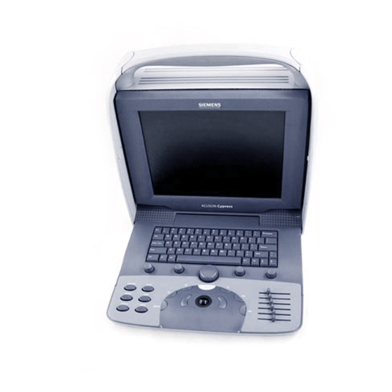
System Overview Overview of the Cypress System TILT MONITOR EXTERNAL CONNECTORS TRANSDUCER CONNECTOR MAGNETO OPTICAL DRIVE ON/OFF SWITCH (ON BACK) CONNECTOR (ON BACK) KEYBOARD TILT MECHANISM KEYBOARD Overview of the Cypress System FIGURE 1. ACUSON Cypress™ Operator’s Manual... -
Page 17: Turning The Cypress System On And Off
Always wait until the screen appears before turning the system FUSE BOX POWER CONNECTION SWITCH POWER CORD – o Cypress System Power Switch FIGURE 2. ACUSON Cypress™ Operator’s Manual... -
Page 18: Turning The Cypress System Off
PRESS THE SETUP KEY AND CLICK THE SHUTDOWN TAB . . . Patient Setup Reports Shutdown Job Patient Name Study Date Location Action Status . . . THEN CLICK Logoff Shutdown Utilities THE SHUTDOWN BUTTON The Shutdown Menu Screen FIGURE 3. ACUSON Cypress™ Operator’s Manual... -
Page 19: Logging On And Off Of The Cypress System
Every user must have a valid User Name and Password. The logon screen opens when the system is started: User Password Shutdown Logging On To logon to the system, follow these steps: Type your User name. Type your Password. Click [ ACUSON Cypress™ Operator’s Manual... -
Page 20: Logging Off
Press the key. SETUP Doubleclick the User Accounts option. On the right side of the screen click the Enabled box. Use the pull-down menu to select the number of minutes that the system should wait before freezing. ACUSON Cypress™ Operator’s Manual... -
Page 21: Setting Up User Accounts
To give other users administrator privileges, click the Administrator box. To add the user, click the [ ] button. If the Password is forgotten or log on is not successful, call the Help Desk at: 1-800-888-SIEM. ACUSON Cypress™ Operator’s Manual... -
Page 22: Editing Or Removing Users
Highlight the User Accounts option. Specify the User Account by selecting the account from the dropdown menu. Make any changes and click [ ] or click [ ] to delete the user from EDIT REMOVE the Cypress system. ACUSON Cypress™ Operator’s Manual... -
Page 23: Connecting And Using Transducers
When transporting the system in a vehicle or over any long distance place transducers securely in a separate packing case. See “Safety, Technical Description, and Accuracy” on page 9-1 for important information on transducer cleaning and infection control. ACUSON Cypress™ Operator’s Manual... -
Page 24: Magneto Optical (Mo) Disk Drive
To insert a disk into the system, load the disk as shown in Figure 5. To remove a disk, press the button located next to the disk bay. NOTE: The system must have power to eject the disk when using the eject button. 1-10 ACUSON Cypress™ Operator’s Manual... -
Page 25: External Devices And Connections
IEC 601-1-1. If you have additional questions, contact your Siemens representative. See Appendix B for information about ink-jet printers. 1-11... -
Page 26: Transporting The System
Moving the Cypress System within a Building Make sure that the transducer is securely placed in the transducer holder. Make sure that all cables are properly secured and that no cables are hang- ing loose. 1-12 ACUSON Cypress™ Operator’s Manual... -
Page 27: Proper Viewing Angle
The images on the Cypress system appear most clearly when the user is look- ing down at the screen at a 15° angle. Tilt the monitor to achieve the best view- ing angle. The monitor tilts from 5° to 30°. 15° Proper Viewing Angle FIGURE 8. 1-13 ACUSON Cypress™ Operator’s Manual... -
Page 28: System Security
For added protection against theft, the Cypress system is equipped with a secu- rity feature. You can purchase a security cable from the vendor of your choice to use with the Cypress system security lock (Siemens does not sell this cable). These cables are most commonly used to secure laptop computers. -
Page 29: Location Of Fan And Vents
Cypress system. VENTS ARE LOCATED ON THE TOP AND BACK OF THE CYPRESS SYSTEM THE FAN IS LOCATED ON THE RIGHT SIDE OF THE CYPRESS SYSTEM Location of Fan and Vents FIGURE 10. 1-15 ACUSON Cypress™ Operator’s Manual... - Page 30 System Overview 1-16 ACUSON Cypress™ Operator’s Manual...
-
Page 31: Keyboard & General Controls
How the function of the Main knob depends on the active mode of the system Using the Soft Window knobs to control the soft windows options located on the bottom of the screen Using the Function keys Using the Alphanumeric keys to enter text data ACUSON Cypress™ Operator’s Manual... -
Page 32: Keyboard Overview
FIGURE 11. The Cypress system keyboard consists of: Seven Mode keys Two < > keys and Trackball ENTER Time/gain compensation ( ) slide-pots The Main knob Four Soft Window knobs Six Function keys An alphanumeric keypad ACUSON Cypress™ Operator’s Manual... -
Page 33: Keyboard Controls
2D image, pressing a second time activates the CW Doppler spectral display. The key then toggles from the CW display to the real-time 2D image. To exit the CW Doppler mode, press ACUSON Cypress™ Operator’s Manual... - Page 34 “Saving Image Data” on page 5-5. Pressing a second time unfreezes the image and FREEZE returns to real-time scanning. Any unsaved loops are lost because loops are stored in temporary memory only. ACUSON Cypress™ Operator’s Manual...
-
Page 35: Trackball And
Slide-pot controls at the bottom affect the mid-field to far-field of the image. In general, the near-field settings should be set relatively low (to the left) and the far-field settings should be set higher (to the right). See illustration at left. ACUSON Cypress™ Operator’s Manual...Keys -
Page 36: Main Knob Functions
Main knob counterclockwise to select and clock- SLOW wise to select FAST This function is available in all full-screen View and Freeze modes when PLAY displayed in the Soft Window controlled by the Main knob. ACUSON Cypress™ Operator’s Manual... -
Page 37: Soft Window Knobs
PRESS DOWN ON THE SOFT WINDOW KNOBS TO CYCLE SETTINGS THROUGH FUNCTIONS OR TO SWITCH BETWEEN THE OPTIONS NOTE: Cardiac and Vascular Soft Window controls may vary depending on the transducer being used and which protocol has been selected. ACUSON Cypress™ Operator’s Manual... - Page 38 These functions are available when the Advanced Triggering option is installed. ** The key is only available when the function is activated; the DELETE PLAY LOOP/PLAY SERIES area will be blank when is activated. PLAY ALL ACUSON Cypress™ Operator’s Manual...
- Page 39 There is no View in FREEZE mode PLAY SERIES FLAG PLAY ALL DELETE PLAY LOOP key is only available when the function is activated; the DELETE PLAY LOOP/PLAY SERIES area will be blank when is activated. PLAY ALL ACUSON Cypress™ Operator’s Manual...
-
Page 40: Function Keys
To adjust the settings, use the Trackball, < > key, and ENTER alphanumeric keypad. To exit the Setup screen, press the key again, or SETUP press any scanning Mode key (except COLOR 2-10 ACUSON Cypress™ Operator’s Manual... - Page 41 SAVE termined time limit is reached. This limit is set in the Save Time Limit field on the System Setup menu or determined by the protocol. 2-11 ACUSON Cypress™ Operator’s Manual...
-
Page 42: Alphanumeric Keys
> while CTRL CTRL using the Cypress Trackball and < > key to highlight items. ENTER & Backspace “ Return Caps Lock ‘ < > Shift Shift ‘ Ctrl The Cypress System Keyboard FIGURE 12. 2-12 ACUSON Cypress™ Operator’s Manual... -
Page 43: Special Marks
> key and press the corresponding SHIFT key shown below. £ Backspace Ä Å É Þ Ü Ú Í Ó Ö Á § Ð Ø ° “ Return Caps Lock Æ Ç Ñ Shift Shift Ctrl 2-13 ACUSON Cypress™ Operator’s Manual... - Page 44 Hold down the < > key and the < > key and press the key with the SHIFT corresponding diacritical mark shown below. Type the alphabetic character key. Backspace ¨ Return ´ Caps Lock Shift Shift ‘ Ctrl 2-14 ACUSON Cypress™ Operator’s Manual...
-
Page 45: Basic Setup
Basic Setup CHAPTER 3 This chapter describes how to use the Function key to configure the SETUP Cypress system. It includes information on: User Accounts Setting parameters for system operation The user-defined Preset settings ACUSON Cypress™ Operator’s Manual... -
Page 46: The Setup Menu
WHEN YOU SELECT AN OPTION, TO DISPLAY THE THE SELECTION INFORMATION FULL LIST OF WILL BE DISPLAYED HERE OPTIONS Patient Setup Reports Shutdown Setup Presets User Accounts Calculations DICOM Network Identification Multimedia Connection System The Setup Menu Screen FIGURE 13. ACUSON Cypress™ Operator’s Manual... -
Page 47: Navigating The Setup Menu
Accounts see “Setting Up User Accounts” on page 1-7. For instructions about how to Logon to the system when User Accounts are set up see “Logging On and Off of the Cypress System” on page 1-5. ACUSON Cypress™ Operator’s Manual... -
Page 48: Explanation Of Setup Menu Fields
Hide System Clock box. To display the system clock while in View mode, remove the checkmark. View Images After Study Activation — When Enabled, it automatically starts the study review after activation (that is, it eliminates the need to press VIEW ACUSON Cypress™ Operator’s Manual... - Page 49 To move the bar, position the Trackball so the arrow is over the bar, then press and hold down the < > key while using the Trackball ENTER to slide the bar. ACUSON Cypress™ Operator’s Manual...
- Page 50 Sets the speed of the double-click used throughout Speed the system (for example, when selecting a patient). To slow down the double-click (i.e., allow more time between clicks), slide the bar to the left. For faster double-click, slide the bar to the right. ACUSON Cypress™ Operator’s Manual...
- Page 51 Patient screen. Language Sets the display language. Select a language from the drop-down menu. Note that when the language is changed, the system must be restarted for the change to take effect. ACUSON Cypress™ Operator’s Manual...
- Page 52 (updates occur when the Mode button is pressed), 2 Sweeps, 3 Sweeps, or 4 Sweeps. Angle Correction Place a checkmark in the box to enable angle correc- tion for all transducers. This enables angle correction on sector (cardiac) transducers. ACUSON Cypress™ Operator’s Manual...
- Page 53 Use when con- NTSC necting a video printer or . Use for the Euro- pean video standard. Use the modes ( RGB NTSC ) with a color video printer. RGB PAL ACUSON Cypress™ Operator’s Manual...
- Page 54 PRINTER Eject MO on Sets the Cypress to eject an MO disk during Shut- Shutdown down. To automatically eject an MO disk during the Shutdown process, click Enabled. To turn automatic eject off, click Disabled. 3-10 ACUSON Cypress™ Operator’s Manual...
- Page 55 See “Quick Text” on page 5-17 for more information. 3D Acquisition This is available with the separate 3D option. The 3D options are: R-Trigger • R-Trigger Signal Out • Go Signal In Step Size in degrees (from 1 to 6 degrees) 3-11 ACUSON Cypress™ Operator’s Manual...
-
Page 56: The Presets Menu
. Color Width . Color Smoothing Beam Steering Persistence . Color Steering Angle Steering . Spectral Compress . Color Box Location . Lateral Gain . Color Persistence . Colorize . Angle Correction . Colormap Filter 3-12 ACUSON Cypress™ Operator’s Manual... -
Page 57: Storing A User-Defined Preset
]. The Preset is loaded when live imaging begins. LOAD NOTE If a Preset is removed (i.e., deleted) after [LOAD] is clicked and before the start of live imaging, the factory default Preset will be loaded. 3-13 ACUSON Cypress™ Operator’s Manual... -
Page 58: Recalling A Saved Preset On The New Patient Screen
Use the pull-down menu to select the Preset option to be deleted. Click [ REMOVE NOTE If a Preset is removed (i.e., deleted) after [LOAD] is clicked and before the start of live imaging, the factory default Preset will be loaded. 3-14 ACUSON Cypress™ Operator’s Manual... -
Page 59: Making Changes To The Current User-Defined Preset
Place a checkmark in the Enabled box. The Preset is loaded when live imaging begins. NOTE If a Preset is removed (i.e., deleted) after [LOAD] is clicked and before the start of live imaging, the factory default Preset will be loaded. 3-15 ACUSON Cypress™ Operator’s Manual... -
Page 60: The System Menu
Explanation of System Menu Fields When System is highlighted the following information is displayed: System Serial Number Software Version Boards Displays part numbers and serial numbers for the boards in the sys- tem. Table 5 describes the System options. 3-16 ACUSON Cypress™ Operator’s Manual... - Page 61 Enable Password Modification Click the check- box to enter a new password. Password Passwords are issued by Siemens. Passwords are unique to each Cypress system and cannot be transferred. Do not delete an exist- ing password until a new password has been issued.
-
Page 62: The Calculations Menu
(i.e., more dots); a higher number specifies a less vivid resolution. Estimates RA Pressure — Type the estimated pressure in the box. The estimate appears in the Report menu when the field is clicked. 3-18 ACUSON Cypress™ Operator’s Manual... - Page 63 Default Vascular Exam Type — Specify the default exam type for vascular studies by selecting an exam type from the pull-down menu and clicking the Default radio button. See “Setting Up Default Sites for Vascular” for more information. 3-19 ACUSON Cypress™ Operator’s Manual...
- Page 64 DICOM DICOM Size screen or just a region of interest (ROI). To set the size, press , double-click , and highlight SETUP DICOM Stress Image Size. Click the radio button to DICOM select the size. 3-20 ACUSON Cypress™ Operator’s Manual...
-
Page 65: The Dicom Menu
Syntax Only box to ensure that the Cypress sys- tem will transfer the images only in the selected format. The secondary default transfer syn- DICOM tax of uncompressed will not be proposed in the association. DICOM 3-21 ACUSON Cypress™ Operator’s Manual... -
Page 66: The Network Identification Menu
( The options include: Name, Remote Share, User Name, Password, and Test Result. See “Multimedia Format to a Computer Via a Net- work” on page 9-5 for more information. 3-22 ACUSON Cypress™ Operator’s Manual... -
Page 67: Patients
Function key to create, view, PATIENT and maintain a patient directory in the Cypress system. It includes information Setting up a patient directory Entering patient information Adding new patients to the directory Creating, editing, and viewing patient studies ACUSON Cypress™ Operator’s Manual... -
Page 68: The Patient Menu
SWITCH BETWEEN SERVER FOR PATIENT (–) SIGN NEXT TO THEM. SEE THE PATIENT LIST AND INFORMATION “Study Formats” on page 4-8 THE STUDY LIST FOR AN EXPLANATION. The Patient Menu — Organized by Patient Name FIGURE 14. ACUSON Cypress™ Operator’s Manual... - Page 69 <1 DOE, WR 36517 04/04/2000.. None <1 Patient List Worklist Storage [MBytes] Study: Free: 3535 SWITCH BETWEEN THE PATIENT LIST AND THE STUDY LIST The Patient Menu — Each Study as a Separate Item FIGURE 15. ACUSON Cypress™ Operator’s Manual...
-
Page 70: Icons Used In The Patient Directory
MO disk in the format can be Cypress reloaded onto the system and then saved in format. DICOM Multimedia Appears in the Patient/Study list when studies Format are transferred to the MO disk in Multimedia for- mat. ACUSON Cypress™ Operator’s Manual... - Page 71 DOE, P List MO Disk: 63 Mbytes free – Worklist DOE, E 12/10/1999 10:40 Storage [MBytes] Study: 01/24/2000 11:10 Free: 3535 STUDY IN DICOM FORMAT MO DISK ICON STUDY IN MULTIMEDIA FORMAT Patient Directory Icons FIGURE 16. ACUSON Cypress™ Operator’s Manual...
-
Page 72: Explanation Of Patient Menu Buttons
Opens the menu to add a new patient (see “Adding a NEW PATIENT New Patient” on page 4-9). Starts a new study for the selected (highlighted) patient NEW STUDY (see “Starting a New Study” on page 4-15). ACUSON Cypress™ Operator’s Manual... - Page 73 DICOM Patient screen, eliminating the need to manually enter ing Feature) the data. Systems with the Networking feature and one or DICOM more Worklist servers configured have the [ WORKLIST button enabled on the Patient screen. ACUSON Cypress™ Operator’s Manual...
-
Page 74: Study Formats
To hide the studies and display only the patient name, click the minus sign. You can also expand or minimize the studies under a patient folder by double- clicking the patient name. ACUSON Cypress™ Operator’s Manual... -
Page 75: Adding And Editing Patients And Studies
If desired, type an ID number (up to 64 characters). The ID number should be unique (e.g., the patient’s date of birth or social security number). Note that the combination of the patient’s last name, first name, and the ID num- ber must be unique. ACUSON Cypress™ Operator’s Manual... - Page 76 When you save an image for these patients, the system will add the date and time of the actual study. : The study information such NOTE 4-10 ACUSON Cypress™ Operator’s Manual...
- Page 77 ]. To save the new entry and go to scan- CANCEL ning mode, press the mode key (or any mode key except ). The COLOR patient now appears in the directory of patients and studies. 4-11 ACUSON Cypress™ Operator’s Manual...
-
Page 78: Registering A New Patient Using The Worklist
Modality Worklist Details screen. The Cypress system New Patient screen will be displayed with these fields filled in: Last Name, First Name, Birth Date, Sex, Accession Number. You will not be able to change any of the data for these fields. 4-12 ACUSON Cypress™ Operator’s Manual... - Page 79 All Modalities to search for patients scheduled on any imaging modality. Worklist Server Select the Worklist Server to be queried. Display Select the number of query results that you want to dis- play. 4-13 ACUSON Cypress™ Operator’s Manual...
-
Page 80: Caching Of Modality Worklist Results
NOTE Once the selected patient is used to create a study, its information is removed from the cache. 4-14 ACUSON Cypress™ Operator’s Manual... -
Page 81: Starting A New Study
Click [ To save the information and return to the display, press SETUP If the patient being examined is not in the system: See “Adding and Editing Patients and Studies” on page 4-9. 4-15 ACUSON Cypress™ Operator’s Manual... -
Page 82: Editing Patient And Study Information
TO DISPLAY THIS Last Name SCREEN TO EDIT First Name Edgar THE PATIENT INFORMATION, QTR3942 Cancel HIGHLIGHT A Birth Date (dd-mm-yyyy) 1944 PATIENT NAME AND Presets CLICK THE [EDIT] Male BUTTON. Editing Patient Information FIGURE 17. 4-16 ACUSON Cypress™ Operator’s Manual... - Page 83 Add Study Metric Weight Averaging mmHg Blood Pressure TO CHANGE THE Study Indication INFORMATION IN Accession # THESE FIELDS Cardiac Routine Protocol USE THE TRACKBALL AND Institution Name KEYPAD Sonographer Miscellaneous Editing Study Information FIGURE 18. 4-17 ACUSON Cypress™ Operator’s Manual...
-
Page 84: Completing A Study With No Patient Name
Setup screen and return to the display or press to return to the display. SETUP Save loops using (see “Saving Image Data” on page 5-5). •SAVE Q SAVE All loop saves are added to the selected study. 4-18 ACUSON Cypress™ Operator’s Manual... -
Page 85: Viewing Existing Patient Studies
NOTE Only the first 25 frames of the loop are displayed when viewing images in quad screen mode. To change the display format, follow these steps: Press the key once to display full-screen mode. VIEW Press again to display quad-screen mode. VIEW To exit, press 4-19 ACUSON Cypress™ Operator’s Manual... -
Page 86: Removing A Study Or Patient From The System
NOTE The Cypress system is not meant to be used for long-term storage of patient studies. Completed studies should be moved to an MO disk or network server. See chapter 9, “Transferring Studies” for more information. 4-20 ACUSON Cypress™ Operator’s Manual... -
Page 87: Batch Removal
Images (all image data not flagged will be deleted). Click [ ] to remove all of the highlighted studies or click [ ] to YES TO ALL confirm deletion of each study, one-at-a-time. To exit, press or any Mode key except COLOR 4-21 ACUSON Cypress™ Operator’s Manual... -
Page 88: Patient Reports
> or by turning the Main knob. ENTER Patient Setup Reports Shutdown PATIENT REPORT Information: Institution: Name: Accession #: Sex: Birth Date: Height: Study Date: Weight: BSA: Indication: Miscellaneous Info: Comment: Text Comments The Patient Report FIGURE 19. 4-22 ACUSON Cypress™ Operator’s Manual... -
Page 89: Adding A Text Comment To A Patient Report
Use the Cypress system keypad or an external keyboard to type in the text box and then click [ The text entered in the text box will appear in the Comments section of the Patient Report. 4-23 ACUSON Cypress™ Operator’s Manual... - Page 90 Patients 4-24 ACUSON Cypress™ Operator’s Manual...
-
Page 91: Scanning
Controls used to complete scans and save images include: The time/gain compensation ( ) controls The Main knob (changes for each scan mode) Soft windows (change for each scan mode) The Tools buttons (how they work for each scan mode) ACUSON Cypress™ Operator’s Manual... -
Page 92: Overview Of The Scanning Process
See the sections in this chapter for specific information about each scanning mode. Basic Steps to Complete a Scanning Session If you are not using the Siemens Cypress cart, place the Cypress system on a stable, level surface. Connect the power cord. -
Page 93: Using Soft Windows
EACH SOFT WINDOW IS CONTROLLED BY ITS SOFT WINDOW CORRESPONDING SOFT KNOBS ON CYPRESS WINDOW KNOB SYSTEM KEYBOARD MAIN KNOB PATIENT CALC SETUP VIEW qSAVE TOOLS SAVE Soft Windows are Controlled by the Soft Window Knobs FIGURE 20. ACUSON Cypress™ Operator’s Manual... -
Page 94: Using Tools
3V2c Pwr M Image MI 1.0 TIs 0.1 Comp 2 Pproc 3 Text GN 5/ / 45fps 16.2cm Harmonic Timer Compress 2D Gain Apex Invert Frequency Depth Function Key Displays the Tools Buttons TOOLS FIGURE 21. ACUSON Cypress™ Operator’s Manual... -
Page 95: Saving Image Data
2, 4, or 6 seconds of data. Q SAVE NOTE When an is not connected to the patient, the Cypress system defaults to a time capture of 2 seconds per loop. ACUSON Cypress™ Operator’s Manual... -
Page 96: Viewing Saved Loops
Cypress system will allow two loops to be deleted—but not the final loop. To delete the remaining loop, the entire study must be removed from the patient’s file. ACUSON Cypress™ Operator’s Manual... -
Page 97: Flagging Images
NOTE In Freeze mode, flagging does not save the data—you must also press either to save the data as part of the patient's •SAVE Q SAVE study. ACUSON Cypress™ Operator’s Manual... -
Page 98: When To Use The Flag Function
Flag the selected images. Press the key and highlight the study Date and Time. PATIENT Click [ SEND In the Multimedia section, check Network as the destination and click the Only Flagged Loops radio box. ACUSON Cypress™ Operator’s Manual... -
Page 99: Cypress System Data
Setting column of the Table as the pound sign (#). There is another set of information about the “trigger modes.” This information is displayed beneath the system data. See “Trigger Modes” on page 5-13 for details about the trigger modes. ACUSON Cypress™ Operator’s Manual... - Page 100 Bone (TIb): Second and third trimester fetal (bone near focus) Compress # Compression or Dynamic Range Use the Main knob to adjust the range. The settings are: 1—9. PProc # Post Processing Indicates the currently selected post-pro- cessing curve. There are 7 curves. 5-10 ACUSON Cypress™ Operator’s Manual...
-
Page 101: Depth
Use the Soft Window FREQUENCY knob to adjust the frequency. Invert Invert Displayed when the spectral doppler flow display has been inverted. The spectrum is inverted using the corre- sponding Soft Window knob. 5-11 ACUSON Cypress™ Operator’s Manual... - Page 102 Soft Window knob. The angle symbol appears in the System Data field when an angle equal to or greater than 1° is selected. The current angle correction setting appears to the right of the symbol. 5-12 ACUSON Cypress™ Operator’s Manual...
-
Page 103: Trigger Modes
Time Increases the trigger time in milliseconds. The range is from 8.0 ms through 1992.0 ms. # Frames Frames Shows the number of frames that are produced in intermittent mode The range is from 1 through 16 frames. 5-13 ACUSON Cypress™ Operator’s Manual... -
Page 104: Keeping Track Of Saved Loops
AND THERE ARE LOOPS TEMPORARILY STORED IN THE SCROLLING MEMORY Pwr M 3V2c Loop 1/5 MI 0.9 TIs 0.1 Comp 2 PProc 3 03:55:40 PM GN 5/ / 13 June 2005 45fps 16.2cm Harmonic Loop Information FIGURE 24. 5-14 ACUSON Cypress™ Operator’s Manual... -
Page 105: Adding Text To An Image
ANNOTATION Pwr M 3V2c MI 0.9 TIs 0.1 Comps 2 PProc 3 <New Annotation> GN 5/ / 45fps 16.2cm Aorta Harmonic Aortic Valve Erase Erase All Delete < Position —— Adding Text Annotations FIGURE 25. 5-15 ACUSON Cypress™ Operator’s Manual... - Page 106 Select the annotation that is to be deleted using the < > key (pressing <TAB> cycles through the annotations on the screen). When the desired annotation is highlighted, press < > to delete it. BACKSPACE 5-16 ACUSON Cypress™ Operator’s Manual...
-
Page 107: Hiding The Factory-Defined List
System Annotations box. To access the System Annota- tions box, follow these steps: Press the function key and select [ TOOLS TEXT Click the checkmark in the System Annotations box to remove the check. 5-17 ACUSON Cypress™ Operator’s Manual... -
Page 108: Quick Text
To remove the highlighted annotation, press the < > key. BACKSPACE To delete all the annotations: Press and hold the < > key and then press the < > key. BACKSPACE To exit Quick Text, press < >. 5-18 ACUSON Cypress™ Operator’s Manual... -
Page 109: Adding An Arrow When Quick Text Is Enabled
Press the < > key until the arrow is highlighted (if there is more than one annotation on the screen the < > key cycles through each). Press the < key to remove the arrow. BACKSPACE> 5-19 ACUSON Cypress™ Operator’s Manual... -
Page 110: Zoom
To exit and return to a full screen display, press the knob. ZOOM Zoom Notes: function can be activated/deactivated only in the full-screen dis- ZOOM play. The Zoom box has a variable number of positions. 5-20 ACUSON Cypress™ Operator’s Manual... -
Page 111: Scanning
2D Gain Frequency 2D SOFT WINDOW PRESS THE MAIN KNOB TO MENU OPTIONS SWITCH BETWEEN See Table 16, “2D COMPRESS AND 2D GAIN Scanning Soft Win- dows Options,” on page 5-23. Scanning Screen FIGURE 26. 5-21 ACUSON Cypress™ Operator’s Manual... -
Page 112: Activate The 2D Display
Gain (the system default) Turn the knob clockwise to increase the overall THE MAIN KNOB amplification of the 2D image data. Turn counterclockwise to decrease. In Freeze mode, turn the Main knob to scroll through the frames or to select the playback speed. 5-22 ACUSON Cypress™ Operator’s Manual... -
Page 113: Soft Windows 5-23
Press < > to enlarge the image. ENTER To reposition or resize the zoom box, turn the knob counterclockwise. Press the Soft Window knob to exit. ZOOM 5-23 ACUSON Cypress™ Operator’s Manual... - Page 114 ) setting. wise. To increase the MI, turn the knob clockwise. setting is displayed in the data field located in the upper left portion of the screen (see Table 14 on page 5-10 for more information). 5-24 ACUSON Cypress™ Operator’s Manual...
- Page 115 Selects the number of ing Soft Window knob to select BEAT beats for intermittent imaging mode. Turn the knob to select a number. The current selection is displayed under the System Data (for example, “1 Beat”). 5-25 ACUSON Cypress™ Operator’s Manual...
- Page 116 Turn the knob to select a number. The range is duced in intermittent from 1 to 16. mode. The current selection is displayed under the System Data (for example, “3 Frames”). 5-26 ACUSON Cypress™ Operator’s Manual...
-
Page 117: Tools
] to add text to an image in either Freeze or Active mode. TEXT Angle Click [ ] to capture a selected area of the image using the (Region In Freeze Mode: of Interest) box. Colorize Click [ ] to start the time counter. TIMER 5-27 ACUSON Cypress™ Operator’s Manual... - Page 118 Thus, 45 fps uses more memory than 33 fps. Studies created with higher frame rates require more time to archive and allow for fewer studies to be archived on the removable disk. 5-28 ACUSON Cypress™ Operator’s Manual...
- Page 119 Restart: Starts the timer clock once it has been stopped. Stop: Stops the timer clock. Off: Stops the timer clock and removes it from the screen. Cancel: Closes the menu without changing the timer clock. 5-29 ACUSON Cypress™ Operator’s Manual...
-
Page 120: Color Flow Scanning
COLOR SOFT WINDOW PRESS THE MAIN KNOB TO MENU OPTIONS SWITCH BETWEEN See Table 18, “Color Flow 2D GAIN AND COLOR GAIN Scanning Soft Windows Options,” on page 5-32. The Color Flow Scanning Screen FIGURE 28. 5-30 ACUSON Cypress™ Operator’s Manual... -
Page 121: Activate The Color Flow Display
Color Gain Turn the knob clockwise to increase the overall amplification of GAIN, PRESS the color flow image data. Turn counterclockwise to decrease. THE MAIN KNOB In Freeze mode, use the Main knob to search frame-by-frame or to set the play- back speed. 5-31 ACUSON Cypress™ Operator’s Manual... -
Page 122: Color Flow Soft Windows
Press < > to enlarge the image. ENTER To reposition or resize the zoom box, turn the knob counterclockwise. Press the Soft Window knob to exit. ZOOM 5-32 ACUSON Cypress™ Operator’s Manual... - Page 123 Reverses the display the corresponding knob to select INVERT of forward and reverse flow Turn the knob to invert the display. Invert is shown to the right side of the image as an inverted color bar. 5-33 ACUSON Cypress™ Operator’s Manual...
- Page 124 Applies a velocity filter to Color Doppler Press the corresponding knob to select FILTER To increase the velocity filter, turn the knob clock- wise. To decrease the velocity filter, turn the knob counterclockwise. 5-34 ACUSON Cypress™ Operator’s Manual...
-
Page 125: Color Flow Tools
] to add text to an image in either Freeze or Active mode. TEXT Colorize Click [ ] to capture a selected area of the image using the (Region In Freeze Mode: of Interest) box. Color Map Click [ ] to start the time counter. TIMER 5-35 ACUSON Cypress™ Operator’s Manual... - Page 126 Colorize Applies a variety of colorized maps overlaying the grayscale image. Colorize is useful in certain situations to optimize contrast resolution. Text Adds text labels to an image. See “Adding Text to an Image” on page 5-15 for details. 5-36 ACUSON Cypress™ Operator’s Manual...
- Page 127 Restart: Starts the timer clock once it has been stopped. Stop: Stops the timer clock. Off: Stops the timer clock and removes it from the screen. Cancel: Closes the menu without changing the timer clock. 5-37 ACUSON Cypress™ Operator’s Manual...
-
Page 128: Continuous Wave Doppler (Cw) Scanning
SOFT WINDOW MENU OPTIONS PRESS THE MAIN KNOB SWITCHES See Table 20, “CW Scanning TO SWITCH BETWEEN BETWEEN SCALE Soft Windows Options,” on VOLUME AND CW GAIN AND FILTER page 5-40. Scanning Screen FIGURE 30. 5-38 ACUSON Cypress™ Operator’s Manual... -
Page 129: Activate The Cw Display
Gain Turn the knob clockwise to increase the amplification of the Dop- VOLUME AND pler signal. Turn counterclockwise to decrease. GAIN, PRESS THE MAIN KNOB In Freeze mode, turn the Main knob to scroll through the frames. 5-39 ACUSON Cypress™ Operator’s Manual... -
Page 130: Cw Soft Windows 5-40
This may be useful in detecting low velocity blood flow. Press the corresponding knob to select SCALE To increase the velocity setting, turn the knob clockwise. To decrease the velocity setting, turn the knob counterclock- wise. 5-40 ACUSON Cypress™ Operator’s Manual... -
Page 131: Cw Tools
In Freeze Mode: Cancel and press < >. ENTER None Click [ ] to add text to an image in either Freeze or Active mode. TEXT Click [ ] to start the time counter. TIMER 5-41 ACUSON Cypress™ Operator’s Manual... - Page 132 Restart: Starts the timer clock once it has been stopped. Stop: Stops the timer clock. Off: Stops the timer clock and removes it from the screen. Cancel: Closes the menu without changing the timer clock. 5-42 ACUSON Cypress™ Operator’s Manual...
-
Page 133: Pulsed Wave Doppler (Pw) Scanning
SOFT WINDOW PRESS THE MAIN KNOB See Table 22, “PW Scanning SWITCHES TO SWITCH BETWEEN Soft Windows Options,” on BETWEEN SCALE VOLUME AND PW GAIN page 5-45. AND FILTER. The PW Scanning Screen FIGURE 32. 5-43 ACUSON Cypress™ Operator’s Manual... -
Page 134: Activate The Pw Display
Gain Turn the knob clockwise to increase the amplification of the Dop- VOLUME AND GAIN, PRESS pler signal. Turn counterclockwise to decrease. THE MAIN KNOB In Freeze mode, turn the Main knob to scroll through the frames. 5-44 ACUSON Cypress™ Operator’s Manual... -
Page 135: Pw Soft Windows 5-45
The selected angle is displayed on the screen. Angle Correction may be activated for all NOTE: transducers by selecting Angle Correction on the Setup menu and putting a checkmark in the Enabled for all transducers box. 5-45 ACUSON Cypress™ Operator’s Manual... -
Page 136: Invert
To decrease the filter setting, turn the knob coun- terclockwise. The filter setting is displayed in the upper left por- tion of the screen in Hertz (Hz) (see “Cypress Sys- tem Data” on page 5-9). 5-46 ACUSON Cypress™ Operator’s Manual... - Page 137 3.0 mm, 4.5 mm, 6.0 mm, 8.0 mm, 10.0 mm, 15.0 mm, 20.0 mm For the V5M transducer, the sizes are: 2.0 mm, 2.4 mm, 3.9 mm, 4.9 mm, 5.9 mm, 8.0 mm, 13.0 mm 5-47 ACUSON Cypress™ Operator’s Manual...
-
Page 138: Pw Tools
In Freeze Mode: Cancel and press < >. ENTER None Click [ ] to add text to an image in either Freeze or Active mode. TEXT Click [ ] to start the time counter. TIMER 5-48 ACUSON Cypress™ Operator’s Manual... - Page 139 Restart: Starts the timer clock once it has been stopped. Stop: Stops the timer clock. Off: Stops the timer clock and removes it from the screen. Cancel: Closes the menu without changing the timer clock. 5-49 ACUSON Cypress™ Operator’s Manual...
-
Page 140: M-Mode Scanning
KNOB TO SWITCH See Table 24, “M-Mode Scan- MARKER). USE THE SWEEP BETWEEN ning Soft Windows Options,” on SPEED BUTTON TO CHANGE COMPRESS AND page 5-52. THE SPEED. 2D GAIN The M-Mode Scanning Screen FIGURE 34. 5-50 ACUSON Cypress™ Operator’s Manual... -
Page 141: Activate The M-Mode Display
Gain Displayed when the time-motion display is active. Turn the knob clock- wise to increase the overall amplification of the M-Mode data. Turn counter- clockwise to decrease. In Freeze mode, turn the Main knob to scroll through the frames. 5-51 ACUSON Cypress™ Operator’s Manual... -
Page 142: M-Mode Soft Windows
Adjusts the sweep speed of the spectral display. Select a sweep number from 1 to 4 where the selection is the num- ber of seconds. For example, Sweep 1 is a 1-second sweep; Sweep 2 is a 2-second sweep; etc. 5-52 ACUSON Cypress™ Operator’s Manual... -
Page 143: M-Mode Tools
In Freeze Mode: Cancel and press < >. ENTER None Click [ ] to add text to an image in either Freeze or Active mode. TEXT Click [ ] to start the time counter. TIMER 5-53 ACUSON Cypress™ Operator’s Manual... - Page 144 Restart: Starts the timer clock once it has been stopped. Stop: Stops the timer clock. Off: Stops the timer clock and removes it from the screen. Cancel: Closes the menu without changing the timer clock. 5-54 ACUSON Cypress™ Operator’s Manual...
-
Page 145: Cardiac Calculations
How to make cardiac measurements Formulas ( , M-Mode, and Doppler) References for the calculations NOTE Review the information regarding measurement and calculations accuracy in Chapter 10, “Safety, Technical Description, and Accu- racy” before starting any calculations. ACUSON Cypress™ Operator’s Manual... -
Page 146: Overview Of Cardiac Measurements
Volume M-Mode Distance Time Slope—with Distance and Time Spectral Doppler Trace—Mean Velocity, Mean Pressure Gradient, TVI, and Time Peak Velocity and Peak Pressure Gradient Time Slope, Time, Peak Velocity, and Peak Gradient Pressure Half-Time and Area ACUSON Cypress™ Operator’s Manual... -
Page 147: Types Of Specific Cardiac Calculations
Right Ventricular Systolic Pressure using LVOT (RVSP) using VSD Mitral Valve Continuity Equation Right Ventricular Systolic Pressure using Pulmonary Artery (RVSP) using Tricuspid Valve Shunt Ratio Regurgitation Time Mitral Valve (MV) Slope Tricuspid Valve (TV) Slope ACUSON Cypress™ Operator’s Manual... -
Page 148: Cardiac Calculations Setup
How to Add or Change an Estimated Value Using Setup Press the key and click the Calculations heading. SETUP Click Estimates. Type the desired estimate into the edit box. The estimate will appear in the Report menu when the field is clicked. ACUSON Cypress™ Operator’s Manual... -
Page 149: How To Edit The Estimated Value While Performing A Calculation
. (To turn averaging , click the checkbox to remove the checkmark.) NOTE Averaging can be activated or deactivated on a per-study basis using the patient information screen independent of the system wide selec- tion in the Setup Menu. ACUSON Cypress™ Operator’s Manual... - Page 150 ] on the Report Menu. CLOSE NOTE There is a maximum of 20 measurements per each averaged result. NOTE Once an averaged result is displayed in a patient report, the averag- ing function cannot be deactivated. ACUSON Cypress™ Operator’s Manual...
-
Page 151: Using The Cardiac Calculations Package
Use the Trackball to highlight the desired type of measurement (for example, Distance) from the menu and press < >. ENTER Use the Trackball to position the first cursor (startpoint) and then press < > to anchor the cursor at that position. ENTER ACUSON Cypress™ Operator’s Manual... - Page 152 Description Single Upper Case A general measurement. Results are displayed in Letter (A) the Selection Menu. Single Lower Case A specific measurement. Results are displayed in Letter (a) the Selection Menu, Report Menu, and Patient Report. ACUSON Cypress™ Operator’s Manual...
-
Page 153: Performing Specific Cardiac Calculations
Main knob FREEZE to search for a frame, or pressing to display stored images. Results VIEW can be viewed in the Report Menu and Patient Report. ACUSON Cypress™ Operator’s Manual... -
Page 154: Saving Calculations To The Patient Report
Results can be viewed at any time by activating the patient study and then click- ing the Report tab. To Delete a Single Measurement from a Report Menu Highlight the measurement with the cursor. Press the < > key to remove that measurement and any associ- BACKSPACE ated measurements. 6-10 ACUSON Cypress™ Operator’s Manual... -
Page 155: Entering A Heart Rate
NOTE For more information regarding the method used to display the heart rate, read the “Heart Rate Information” section located in Table 57 on page 10-28. 6-11 ACUSON Cypress™ Operator’s Manual... -
Page 156: Saving Frames Containing Measurement Graphics
< >. To delete all of the mea- BACKSPACE surements, click [ CLEAR NOTE If the deleted measurement is part of a formula, all the formula results that use that measurement are also deleted. 6-12 ACUSON Cypress™ Operator’s Manual... -
Page 157: Making Corrections To The Trace And Area Measurements
Viewing the Patient Report There are two ways of viewing the Patient Report: While in the calculation package, select Report from the calculation Selection Menu. At any time, press the function key and click the Reports tab. PATIENT 6-13 ACUSON Cypress™ Operator’s Manual... -
Page 158: Changing The Position Of A Calc Menu
Click the radio button that corresponds to the corner of the screen where you want the menus located. CALC Press the key to exit the menu. SETUP 6-14 ACUSON Cypress™ Operator’s Manual... -
Page 159: Cardiac Formulas And References
• Cardiac Output l/min SV HR ------------------------- - 1000 SV is stroke volume (ml). HR is heart rate (bpm). Cardiac Index l/min/m ---------- - CO is cardiac output (l/min). BSA is Body Surface Area (m 6-15 ACUSON Cypress™ Operator’s Manual... - Page 160 Flow Area ---- - ⎝ ⎠ d is diameter (cm). Fractional ⎛ ⎞ LVd LVs – • % FS -------------------------- ⎝ ⎠ Shortening (% FS) LVd is diastolic dimension (cm). LVs is systolic dimension (cm). 6-16 ACUSON Cypress™ Operator’s Manual...
- Page 161 ⎞ LVPWs LVPWd – • % FT -------------------------------------------- - ⎝ ⎠ Thickening– LVPWd Left Ventricular LVPWs is Left Ventricular Posterior Wall in systole. Posterior Wall LVPWd is Left Ventricular Posterior Wall in diastole. (% FT) 6-17 ACUSON Cypress™ Operator’s Manual...
-
Page 162: M-Mode Formulas
Stroke Volume Vd Vs – Cubed Vd is diastolic volume cubed (ml). Vs is systolic volume cubed (ml). Stroke Volume Vd Vs – Teichholz Vd is diastolic volume Teichholz (ml). Vs is systolic volume Teichholz (ml). 6-18 ACUSON Cypress™ Operator’s Manual... - Page 163 LVMI ---------------------- - (LVMI) LV Mass (g). BSA is Body Surface Area (m Body Surface 0.425 0.725 0.007184 W Area (BSA) W is weight (kg) (range: 0.5—160.0 kg). H is height (cm) (range: 15.0—204.0 cm). 6-19 ACUSON Cypress™ Operator’s Manual...
-
Page 164: Doppler Formulas
V is the average velocity between two successive velocity trace points (m/s). N is the number of velocity trace points. Δ is the time increment between two successive velocity trace points (seconds). Time Velocity area under curve Integral 6-20 ACUSON Cypress™ Operator’s Manual... - Page 165 AVA is Aortic Valve Area (cm is Cross-sectional Area of LVOT (cm LVOT Vmax is the maximum velocity in the LVOT (m/s). LVOT Vmax is the maximum velocity across the aortic valve (m/s). LVOT is Left Ventricular Outflow Tract. 6-21 ACUSON Cypress™ Operator’s Manual...
- Page 166 Right Atrial pressure (mmHg). Tricuspid is regurgitant Velocity of tricuspid valve (m/s). Regurgitation Right Ventricu- mmHg RVSP – lar Systolic Pressure from is systolic Blood Pressure (mmHg). Ventricular is maximum Velocity of ventricular septal defect (m/s). Septal Defect 6-22 ACUSON Cypress™ Operator’s Manual...
- Page 167 Formula Units Shunt Ratio — ------ - -------------- is pulmonic Cardiac Output (l/min). is systemic Cardiac Output (l/min). Shunt l/min Qp Qs – – Difference is pulmonic Cardiac Output (l/min). is systemic Cardiac Output (l/min). 6-23 ACUSON Cypress™ Operator’s Manual...
-
Page 168: Cardiac Calculation References
Results of a Survey of Echocardiographic Measurements. Circulation, 1978; 58: 1072–1083. 12. Teichholz, LE, et al. Problems in Echocardiographic Volume Determinations: Echocardiographic-Angiographic Correlations in the Presence or Absence of Asynergy. American Journal of Cardiology, 1976; 37: 7-11. 6-24 ACUSON Cypress™ Operator’s Manual... -
Page 169: Vascular Calculations
This chapter includes information about: How to make vascular measurements Formulas ( and Doppler) References for the calculations NOTE Review the information regarding measurement and calculations accuracy in Chapter 10, “Safety, Technical Description, and Accu- racy” before starting any calculations. ACUSON Cypress™ Operator’s Manual... -
Page 170: Overview Of Vascular Measurements
Velocity PI: PS (Peak Systolic), ED (End Diastolic), S/D (Systolic/Diastolic), PI (Pulsatility Index), RI (Resistance Index), TAVmax (Time-Averaged Maximum Velocity) RI: PS (Peak Systolic), ED (End Diastolic), S/D (Systolic/Diastolic), RI (Resistance Index) Acceleration: Vel (Velocity), Time ACUSON Cypress™ Operator’s Manual... -
Page 171: Types Of Specific Vascular Calculations
CCA, ICA, ECA, Bulb, Vert, Subclav, ICA/CCA, PSV/EDV Left Carotid: CCA, ICA, ECA, Bulb, Vert, Subclav, ICA/CCA, PSV/EDV Arterial: Vel, PI, RI, Accel Venous: Time Ratios: A/B Volume Flow: TAVmax, Area NOTE There are no specific vascular calculations for M-Mode. ACUSON Cypress™ Operator’s Manual... -
Page 172: Vascular Calculations Setup
NOTE When defining a portion of a image, no part of the outline can intersect another segment of the outline. ACUSON Cypress™ Operator’s Manual... -
Page 173: Selecting A Report Format
NOTE For Ratios, remember to complete the specifications for both sites. NOTE The site labels are abbreviated in the menu. The abbreviations are displayed at the top of the Add window and in the Calculations menu. ACUSON Cypress™ Operator’s Manual... -
Page 174: Editing Default Vascular Sites
To change the position of a specific site, highlight the site (for example, R ICA), and click the up (/\) or down (\/) arrows to move the site up or down the list. ACUSON Cypress™ Operator’s Manual... -
Page 175: Using The Vascular Calculations Package
Use the Trackball to highlight the desired type of measurement (for example, Velocity) from the menu and press < >. ENTER Use the Trackball to position the cursor (startpoint) and then press < > ENTER to anchor the cursor at that position. ACUSON Cypress™ Operator’s Manual... - Page 176 Description Single Upper Case A general measurement. Results are displayed in Letter (A) the Selection Menu. Single Lower Case A specific measurement. Results are displayed in Letter (a) the Selection Menu, Report Menu, and Patient Report. ACUSON Cypress™ Operator’s Manual...
-
Page 177: Performing Specific Vascular Calculations
> to set. Images can be obtained by scanning the ENTER patient and then pressing and using the Main knob to search for a FREEZE frame, or pressing to display stored images. Results can be viewed in VIEW the Report Menu and Patient Report. ACUSON Cypress™ Operator’s Manual... -
Page 178: Saving Calculations To The Patient Report
The camera icon will briefly appear in the upper right corner of the screen to indicate the graphics have been added to the frame. The graphics can only be viewed by using the Main knob to search for the frame. 7-10 ACUSON Cypress™ Operator’s Manual... -
Page 179: Deleting A General Measurement
> key to BACKSPACE erase a small portion of the outline. Press and hold the < > key to BACKSPACE continuously erase the path of the cursor until the < > key is BACKSPACE released. 7-11 ACUSON Cypress™ Operator’s Manual... -
Page 180: Stopping A Measurement Before Completion
7-12 ACUSON Cypress™ Operator’s Manual... -
Page 181: Setting A Default Position For The Calc Menu
Click the radio button that corresponds to the corner of the screen where you want the menus located. CALC Press the key to exit the menu. SETUP 7-13 ACUSON Cypress™ Operator’s Manual... -
Page 182: Vascular Formulas And References
Factor 60 converts to ml/min. HWL (Volume) × π × × × -- - -- - ---- - --- - L is the longitudinal axis. W is the transverse axis. H is the anteroposterior axis. 7-14 ACUSON Cypress™ Operator’s Manual... -
Page 183: Doppler Formulas
Highest ICA Velocity --------------------------------------------------- - Carotid/ Mid CCA Velocity Common ICA velocity is the highest Internal Carotid Artery Peak Sys- Carotid Ratio tolic velocity. (IC/CC) CCA velocity is the mid Common Carotid Artery Peak Systolic velocity. 7-15 ACUSON Cypress™ Operator’s Manual... -
Page 184: Vascular Calculation References
5. Daigle, R., Techniques in Noninvasive Vascular Diagnosis (second edition). Summer Publishing. 2002. Littleton, CO. 6. Chervenak, F., Isaacson, G., Campbell, S., Ultrasound in Obstetrics and Gynecology (Volume 1; First Edition) Little, Brown 1993. Boston. 7-16 ACUSON Cypress™ Operator’s Manual... -
Page 185: Imt Options Package
IMT Options Package IMT Options Package The IMT (Intima-Media Thickness) measurements package is a separate option for use with the ACUSON Cypress ultrasound system. These pages describe how to set up and use the IMT options. IMT Setup Options To set the IMT options, follow these steps: Press the key. -
Page 186: Using The Imt Calculations Package
------ ------ ------ 60° ------ ------ ------ ------ ------ ------ ------ 180° ------ ------ ------ 150° ------ ------ ------ 120° ------ ------ ------ 90° ------ ------ ------ 60° ------ ------ ------ ------ ------ ------ ------ 7-18 ACUSON Cypress™ Operator’s Manual... -
Page 187: Turning The Imt Grid On And Off
(Angle corresponds to an arc angle device). To add labels during an IMT exam, follow these steps: Turn the Protocol Soft Window knob to scroll through the screen labels for IMT until the desired label is displayed. 7-19 ACUSON Cypress™ Operator’s Manual... -
Page 188: Imt Formulas
4. Howard, G., Sharrett, A.R., Heiss, G., Evans, G.W., Chambless, L.E., Riley, W.A., Burke, G.L., Carotid artery intimal-medial thickness distribution in general populations as evaluated by B-mode ultrasound. ARIC Investigators. Stroke, 1993 Sep; 24 (9): 1297-1304. 7-20 ACUSON Cypress™ Operator’s Manual... -
Page 189: Stress Echo
How to achieve the best signal quality during stress echo exams How to reduce artifacts Using the stress setup controls The stress protocols Conducting the stress exam — including Rest Stage, Immediate Post and Peak, and Pharmacological Stress ACUSON Cypress™ Operator’s Manual... -
Page 190: Connecting And Using Ecg
Stress Echo Connecting and Using to display electrocardiogram waveforms. Siemens provides an adapter that connects into the back of the Cypress system. WARNING The Cypress system is not intended for use as an monitor or for diagnostic . Signals displayed are for reference or triggering only. -
Page 191: Stress Echo Ecg Cables And Connectors
All of the adapters described in this section are included in the Stress Echo option package. Stress Echo ECG Connectors Siemens ships a variety of connectors with every Cypress Stress Echo option package. This ensures that the Cypress system can be properly connected to most stress systems. - Page 192 PORT ON BACK OF CYPRESS SYSTEM ATTACH TO ONE END OF BNC CABLE CONNECT TO STRESS ATTACH TO SYSTEM OTHER END (USE THE OF BNC PLUG THAT CABLE FITS YOUR SYSTEM) ECG-to-BNC Connector and BNC-to-Stress System Plugs FIGURE 36. ACUSON Cypress™ Operator’s Manual...
- Page 193 Connecting and Using ECG Stress Echo ECG Cable CABLE WITH BNC CONNECTOR AT EACH END ATTACH CONNECTORS TO EACH END OF THE CABLE AS Stress Echo ECG Cable FIGURE 37. ACUSON Cypress™ Operator’s Manual...
-
Page 194: Ecg Signal Quality During Stress Echo Exam
Use a square-wave pulse output. Your electrocardiograph unit may also provide a square-wave pulse output signal which can be input into the Cypress system input. This output signal can be used to provide a more robust R-wave trigger signal. ACUSON Cypress™ Operator’s Manual... -
Page 195: About The Stress Protocols
Stage 2 (four views) Stage 3 Peak Stage 4 Post Pharmacological Stage 1 Base AP2, 4-Stage VIEW5, VIEW6 (six views) Stage 2 AP2, VIEW5, VIEW6 Stage 3 Peak AP2, VIEW5, VIEW6 Stage 4 Post AP2, VIEW5, VIEW6 ACUSON Cypress™ Operator’s Manual... - Page 196 See “Using the Pro- tocol Soft Window Knob” on page 8-10. Pressing the key during the Impost and Peak stages will capture loops for •SAVE two consecutive minutes or until the key is pressed a second time. •SAVE ACUSON Cypress™ Operator’s Manual...
-
Page 197: Important Stress Controls
(Region of the Tools menu. Interest) The region of interest box may be repositioned after a loop has been saved by playing the loop back in full-screen for- mat and clicking the [ ] button. ACUSON Cypress™ Operator’s Manual... -
Page 198: Using The Protocol Soft Window Knob
To display the first stage, turn the knob one click clockwise. Each PROTOCOL clockwise click will then display a label with both Stage and View. Turn the knob until the desired label is displayed. PROTOCOL 8-10 ACUSON Cypress™ Operator’s Manual... -
Page 199: Deleting Unlabeled Loops From A Study
Double-click the tab. DICOM Highlight the DICOM Stress Image Size subtitle and an option menu will appear on the right side of the screen. Click the desired option. Press the key to exit the menu. SETUP 8-11 ACUSON Cypress™ Operator’s Manual... -
Page 200: Stress Echo Tools
Restart: Starts the timer clock once it has been stopped. Stop: Stops the timer clock. Off: Stops the timer clock and removes it from the screen. Cancel: Closes the menu without changing the timer clock. 8-12 ACUSON Cypress™ Operator’s Manual... -
Page 201: Conducting A Stress Echo Protocol Exam
Protocol Carotid Routine Cardiac Institution Name 2 Stage Exercise Upper Extremity Lower Extremity 3 Stage Exercise General Sonographer Pharmacological Contrast Miscellaneous CLICK THE DOWN ARROW TO DISPLAY THE LIST OF PROTOCOLS. HIGHLIGHT THE PROTOCOL NAME. 8-13 ACUSON Cypress™ Operator’s Manual... - Page 202 PROTOCOL window. Rest ACTIVE LAX 0 STAGE SAX 0 AP4 0 VIEW AP2 0 COUNTER Compress Apex In Gain Frequency Protocol Depth 8-14 ACUSON Cypress™ Operator’s Manual...
- Page 203 Begin scanning the patient starting with the view. Once the image has been optimized, press . If you set the Save Time Limit to four •SAVE seconds, the Cypress system stores four seconds of data. To view the 8-15 ACUSON Cypress™ Operator’s Manual...
- Page 204 — For Pharmacological: Press to exit View mode. Turn the PROTOCOL knob to display Low. “Low” is displayed in the lower left corner of the screen, and the view counters are reset to zero. 8-16 ACUSON Cypress™ Operator’s Manual...
- Page 205 . A "1" appears next to PROTOCOL view counter. Continue turning the knob to select and PLAY LOOP label the remaining three views. box can be repositioned while in full-screen display. Use the Trackball to move the 8-17 ACUSON Cypress™ Operator’s Manual...
- Page 206 Once all four views have been captured for each stage and assigned a View label, press to display the quad-screen format. VIEW To stop the timer, press click [ ] and then select Stop. TOOLS, TIMER 8-18 ACUSON Cypress™ Operator’s Manual...
-
Page 207: Quad-Screen Soft Windows
(select quad) knob to move the box to the desired quad. SEL QUAD Turn the knob to display the additional loops. The loop counter in NEXT LOOP the top left corner of each quad indicates the number of the loop currently playing. 8-19 ACUSON Cypress™ Operator’s Manual... -
Page 208: Removing A Label
Soft Window knob to move the box to the desired quad. SEL QUAD To display the loop in full-screen, press the key. VIEW Turn the Soft Window knob to display the desired stage/view PROTOCOL label. To return to the quad-screen display, press VIEW 8-20 ACUSON Cypress™ Operator’s Manual... -
Page 209: Labeling Views
Suspending the Protocol Labeling Function To suspend the protocol labeling function, use the Soft Window PROTOCOL knob. To suspend labeling, follow these steps: Start a stress echo exam. Turn the knob until labels are no longer visible. PROTOCOL 8-21 ACUSON Cypress™ Operator’s Manual... -
Page 210: Save The Loop And Then Assign A Label
Note: The timer will start automatically and continue for two minutes, when the • key is pressed during a 2-Stage Protocol immediate post exercise SAVE stage. The timer also may be started manually. See “Viewing the Quad-Screen Display” on page 8-23. 8-22 ACUSON Cypress™ Operator’s Manual... -
Page 211: Viewing The Quad-Screen Display
TURN THE KNOB CLOCKWISE TURN THE KNOB COUNTER- TO REMOVE FRAMES FROM CLOCKWISE TO REMOVE THE START OF THE LOOP. FRAMES FROM THE END OF THE LOOP. See Figure 39 on page 8-24 for more details. 8-23 ACUSON Cypress™ Operator’s Manual... - Page 212 SOFT WINDOW. PRESS THE SWITCH KNOB TO CYCLE THROUGH THE BETWEEN FUNCTIONS (START AND END) PAUSE AND AND THEN TURN THE KNOB TO THE SPEED ADJUST THE FUNCTION. Quad-Screen Format for Stress Echo FIGURE 39. 8-24 ACUSON Cypress™ Operator’s Manual...
-
Page 213: Trimming Frames From A Loop
Turn the Soft Window knob until the best image is playing. PLAY LOOP Position the Press or • to capture the loop. A "1" will appear next to LAX in Q SAVE SAVE the view counter. 8-25 ACUSON Cypress™ Operator’s Manual... -
Page 214: Save And Label The Loop Simultaneously
Note: The timer will start automatically and continue for two minutes, when the • key is pressed during a 2-Stage Protocol immediate SAVE Q SAVE post exercise stage. The timer can also be started manually by clicking ] and selecting Start. TIMER 8-26 ACUSON Cypress™ Operator’s Manual... -
Page 215: Transferring Studies
Reading studies on a compatible viewer DICOM Troubleshooting file transfers NOTE The Cypress system is not meant to be used for long-term storage of patient studies. Completed studies should be moved to an disk or network. ACUSON Cypress™ Operator’s Manual... -
Page 216: Exporting Images From The Cypress System
It is up to the user to determine compatibility between the Cypress system images and the review station. Refer to the Conform- DICOM DICOM DICOM ance Statements for the Cypress system and the review station for their respective capabilities. ACUSON Cypress™ Operator’s Manual... -
Page 217: Native Cypress System Format To Mo Disk
1—3 digit numbers (from 0 to 255), separated by periods. Subnet Mask: See your Network Administrator to determine your Subnet Mask. This number, combined with the IP address, identifies the network that your computer is part of. ACUSON Cypress™ Operator’s Manual... -
Page 218: Dicom Format To A Dicom Server Via A Network
The DICOM Cypress system can save loops that range in size from a single frame to the maximum of 32 seconds. Select a loop size that is compatible to your DICOM viewer. ACUSON Cypress™ Operator’s Manual... -
Page 219: Multimedia Format
NOTE Using the multimedia connection does not require installation of the Networking option. You can connect the Cypress system to your computer through a network Hub using a 10/100 Base T Ethernet cable or a with a direct connection using an Ethernet crossover cable. ACUSON Cypress™ Operator’s Manual... -
Page 220: Explanation Of Dicom Menu Fields
Accept When the box is checked, the Cypress system will query Storage server to verify that all images in the study DICOM Commitment have been properly received and stored. Check the shut- down page for messages. ACUSON Cypress™ Operator’s Manual... - Page 221 The default time-out and minimum value is 5 seconds. Network Defines the number of seconds allowed before a time-out Time-out 2 error is declared on an expected response. The default time-out and minimum value is 60 seconds. ACUSON Cypress™ Operator’s Manual...
-
Page 222: Changing Server Information
Set the Server IP Address. This is the IP address of the server DICOM where images will be sent. Set the Port Number. This is the remote port on the server that is to receive the connection request. The default setting is 104. ACUSON Cypress™ Operator’s Manual... - Page 223 Set the Network Timeout 2 value. This defines the number of seconds allowed before a time-out error is declared on an expected response. The default time-out and minimum value is 60 seconds. Press any mode key to return to live imaging. ACUSON Cypress™ Operator’s Manual...
-
Page 224: Dicom Storage Commitment
Highlight Network Adapter. Click [ RUN SELECTED Set the Speed and Duplex options using the radio buttons. Click [ NOTE To return to imaging, click [ ]; to restart and activate the CLOSE changes, click [ SHUTDOWN 9-10 ACUSON Cypress™ Operator’s Manual... -
Page 225: Dicom Setup For Modality Worklist
DICOM ] button. The system will test the connection and indicate its results in PING this field. If the ping is successful, test the connection by clicking the DICOM ] button. VERIFY 9-11 ACUSON Cypress™ Operator’s Manual... -
Page 226: Dicom Setup For Storage Commitment
[ ] button. The system will test the connection and indi- PING cate its results in this field. If the ping is successful, test the connec- DICOM tion by clicking the [ ] button. VERIFY 9-12 ACUSON Cypress™ Operator’s Manual... -
Page 227: Connecting The Cypress System To A Network
Any time that you make changes, click [ ] and then [ ] to confirm the PING VERIFY connection to the network using the new settings. The Cypress system will respond with a status message in the Test Result field. 9-13 ACUSON Cypress™ Operator’s Manual... -
Page 228: Transferring Studies
]. When the Patient List is dis- PATIENT LIST played, the button is labeled [ STUDY LIST The list last displayed before shutdown is the list displayed when the PATIENT key is pressed after the system is powered up. 9-14 ACUSON Cypress™ Operator’s Manual... - Page 229 MO Disk: 63 Mbytes free – Worklist DOE, E 12/10/1999 10:40 Storage [MB] Study: Free: 3535 CLICK HERE TO SWITCH BACK AND FORTH BETWEEN THE PATIENT LIST AND THE STUDY LIST The Patient List FIGURE 41. 9-15 ACUSON Cypress™ Operator’s Manual...
- Page 230 <1 DOE, WR 36517 04/04/2000.. None <1 Patient List Worklist Storage [MB] Study: Free: 3535 CLICK HERE TO SWITCH BACK AND FORTH BETWEEN THE PATIENT LIST AND THE STUDY LIST The Study List FIGURE 42. 9-16 ACUSON Cypress™ Operator’s Manual...
-
Page 231: Sending The Studies
RLE Lossless Entire Study JPEG Lossy Only flagged loops JPEG Compression Multimedia Format High Archives Report Remove Name, ID from Images Images Entire Study Remove study after Only flagged loops transfer The Send Screen FIGURE 43. 9-17 ACUSON Cypress™ Operator’s Manual... - Page 232 NOTE If the Cypress system is in an imaging mode (active, frozen, or view) while data is being prepared for transfer, the system may pause during the transfer preparation process. Press PATIENT SETUP exit the imaging mode and to allow the transfer preparation process to continue. 9-18 ACUSON Cypress™ Operator’s Manual...
- Page 233 Compression: The Compression scale. JPEG JPEG — a setting results in a higher image quality LOWER and larger file sizes. — a setting results in lower image quality and HIGHER smaller file sizes. 9-19 ACUSON Cypress™ Operator’s Manual...
- Page 234 Patient ID elements, (0010, 0010) and (0010, 0020) DICOM respectively, will still contain the valid patient identifying information for the image. NOTE The name and ID cannot be removed from images archived in the Cypress format. 9-20 ACUSON Cypress™ Operator’s Manual...
-
Page 235: Troubleshooting A Network Dicom Transfer
Verify that the server is on-line. Test An internal DICOM error has occurred - Save canceled the connection by using the ] button on the VERIFY DICOM Server Information section located in the Setup menu. 9-21 ACUSON Cypress™ Operator’s Manual... -
Page 236: Transferring Studies Using The Mo Drive
Note that manual ejection may not be possible during and just after shutdown. DISK INSER- TION SLOT MANUAL EJECTION HOLE EJECT BUTTON/ BUSY LED Magneto Optical Disk Drive FIGURE 44. 9-22 ACUSON Cypress™ Operator’s Manual... -
Page 237: Formatting Disks
CLOSE NOTE If a transfer is attempted to an unformatted MO disk, the transfer is paused and the user given the opportunity to format the disk, erasing its contents, prior to completing the transfer process. 9-23 ACUSON Cypress™ Operator’s Manual... -
Page 238: Reading Native Cypress System Format Studies From The Mo Disk
MO CYPRESS the Cypress system by highlighting the study and then clicking the [ ACTI- ] button. VATE NOTE Studies stored in the format cannot be copied back to the DICOM Cypress system for viewing. 9-24 ACUSON Cypress™ Operator’s Manual... -
Page 239: Copying Studies From An Mo Disk To The Cypress System (Batch Restore)
If you want to restore everything from the disk, click the [ PATIENT LIST and highlight the disk icon. To restore only selected studies, click the ] and highlight the studies you want to restore. STUDY LIST Click [ RESTORE 9-25 ACUSON Cypress™ Operator’s Manual... -
Page 240: Troubleshooting An Mo Disk Transfer
Cypress has been inserted. You the utilities menu and then save the will not be able to save stud- study. Otherwise, insert a disk con- ies to this disk. taining only Cypress studies or a new MO disk. 9-26 ACUSON Cypress™ Operator’s Manual... -
Page 241: Safety, Technical Description, And Accuracy
Important Warnings and Notices Intended Use of the Cypress system Information about specific types of studies including: Cardiac, Intraoperative, Pediatric, Neonatal Cephalic, Peripheral Vascular, Fetal, and Abdominal. Patient Safety Operator Safety Issues Standards Compliance and Other Safety Information 10-1 ACUSON Cypress™ Operator’s Manual... -
Page 242: Important Warnings And Notices
NOTE The shallowest 10% of the scanning depth (nearest the transducer face) is not displayed. For example, if a scanning depth of 16.2 cm is selected, the shallowest 1.6 cm is not displayed. To view the extreme near field, reduce the scanning depth. 10-2 ACUSON Cypress™ Operator’s Manual... -
Page 243: Intended Use
All scanning modes may be applied for each application. The Cypress system contains three measurement and analysis applications: General Cardiac Vascular WARNING The Cypress system is not intended for use as an monitor or for diagnostic . Signals displayed are for reference or triggering only. 10-3 ACUSON Cypress™ Operator’s Manual... -
Page 244: Cardiac Studies
Detect abnormalities in heart anatomy and blood flow during cardiac surgery. Monitor cardiac function during cardiac surgery. Intraoperative Cardiac Studies Table TABLE 48. Target Approach Patients Heart and Transthoracic Adult, pediatric, neonatal Vessels (Epicardial with ster- ile sheath) 10-4 ACUSON Cypress™ Operator’s Manual... -
Page 245: Pediatric Studies
Detect abnormalities, such as abnormal ventricle size or a shift in the midline or flow abnormalities. Neonatal Cephalic Studies Table TABLE 50. Target Approach Patients Intact fontanelles Infants Brain Structures NOTE The 5 MHz external transducer is the only transducer intended for neonatal cephalic studies. 10-5 ACUSON Cypress™ Operator’s Manual... -
Page 246: Peripheral Vascular Studies
Peripheral Vascular Studies Table TABLE 51. Target Approach Patients Cerebrovascular Neck Adult, pediatric, and neonatal arteries and veins Upper extremity Arms Adult, pediatric, and neonatal arteries and veins Lower extremity Legs Adult, pediatric, and neonatal arteries and veins 10-6 ACUSON Cypress™ Operator’s Manual... -
Page 247: Fetal Studies
In addition, visualization of the fetus solely for educational or commercial demonstrations without medical benefit should not be performed.” 10-7 ACUSON Cypress™ Operator’s Manual... -
Page 248: Abdominal Studies
User Manual and Directions for Use that come with AcuNav catheter. NOTE The AcuNav diagnostic ultrasound catheter is available only at cer- tain hardware revision levels. Contact your Siemens representative for additional information. 10-8... -
Page 249: Patient Safety
Medical Ultrasound Safety that is included with this manual. This document explains the interaction of ultrasound and tissue, the possibilities and mecha- nisms of bioeffects, and it explains the output display indices employed by the Cypress system. 10-9 ACUSON Cypress™ Operator’s Manual... -
Page 250: Reducing Acoustic Exposure On The Cypress System - Implementing Alara
Select the appropriate system protocol when performing fetal neonatal ceph- alic studies. This will provide lower default values and provide access to indices for neonatal cephalic studies. Keep exams as brief as possible, consistent with diagnostic requirements. As Low As Reasonably Achievable. 10-10 ACUSON Cypress™ Operator’s Manual... -
Page 251: Electrical Warnings
There have been reports of severe allergic reactions to medical devices containing latex. Operators are advised to identify latex-sensitive patients and to be prepared to treat allergic reactions promptly. For additional information (in the U.S.A.) refer to the Alert which is reproduced on page 10-14. 10-11 ACUSON Cypress™ Operator’s Manual... -
Page 252: Sterilization
Wipe the transducer handle with a cloth moistened with an isopropyl alcohol solution (rubbing alcohol). CAUTION In disinfecting external transducers, be careful to immerse only the top portion of the transducer, up to one inch (2.5 cm) from the transducer 10-12 ACUSON Cypress™ Operator’s Manual... -
Page 253: Infection Control Reference
On March 29, 1991, the U.S. Food and Drug Administration published a medical alert on latex products. Users should study this alert prior to using any latex products. 10-13 ACUSON Cypress™ Operator’s Manual... -
Page 254: U.s. Food And Drug Administration Medical Alert
For example, a health profes- sional could wear a non-latex glove over the latex glove if the patient is sensitive. If both the health professional and the patient are sensitive, 10-14 ACUSON Cypress™ Operator’s Manual... -
Page 255: Peripheral Device Connections
IEC 601-1-1. If you have additional questions, contact your SIemens representative. 10-15 ACUSON Cypress™ Operator’s Manual... -
Page 256: Ultrasound Contrast Agents
Ultrasound Contrast Agents The Cypress system may be used with legally marketed ultrasound contrast agents. Siemens makes no claims regarding the safety or efficacy of ultrasound contrast agents. It is important that you carefully follow the indications, instruc- tions for use, warnings, and cautions that are provided by ultrasound contrast agent manufacturers as a part of the product labeling. -
Page 257: Operator Safety Issues
Mercer, et. al., Occupational health hazards to the ultrasonographer and their possible prevention, Journal of the American Society of Echocardiography, 10:4, 363-366, May 1997. Craig, M. Occupational health hazards of sonography: an update. Journal of Diagnostic Medical Sonography, 1: 47- 50, 1990. 10-17 ACUSON Cypress™ Operator’s Manual... -
Page 258: Glutaraldehyde Exposure
Carefully follow the infection control procedures described in this manual. Blood on the system and transducer should be removed using soap and water followed by alcohol. Dry the equipment afterwards. 10-18 ACUSON Cypress™ Operator’s Manual... -
Page 259: Transporting And Placing The System
Remove transducers from the system when transporting it any distance, or in a vehicle. When transporting transducers, place them in a carrying or ship- ping case. See “Technical Description and Accuracy” on page 10-20 for more informa- tion about transporting specifications. 10-19 ACUSON Cypress™ Operator’s Manual... -
Page 260: Technical Description And Accuracy
Safety, Technical Description, and Accuracy Technical Description and Accuracy Specifications Model ACUSON Cypress™ Manufacturer Siemens Medical Solutions USA, Inc. 1230 Shorebird Way Mountain View, CA 94043 650-969-9112 Electrical Power Requirements Input Voltage: 100—120 V/220—240 V Frequency: 50/60 Hz Current: 1.2/0.6 A Fuse Rating: 2.5A SB-250 V... - Page 261 Siemens will make available, upon request, circuit diagrams, component part lists, descriptions or other information to assist the user’s appropriately qualified technical personnel to repair those parts of equipment which are designated by Siemens as repairable. NOTICE See the “System Overview” section and the beginning of this section for information on the safe installation and operation of the Cypress system.
-
Page 262: Electromagnetic Interference
During operation, the ultrasound image should be expected to experience severe interference that may make the image unusable. This interference stops as soon as the turned off. 10-22 ACUSON Cypress™ Operator’s Manual... -
Page 263: Labeling Icons
Microphone Input Connector for attaching microphone. Video Output Connector for attaching video display monitor or video recording device. External Keyboard Connector for attaching external PC- compatible keyboard. 10-23 ACUSON Cypress™ Operator’s Manual... - Page 264 A security cable can be purchased for added protection against theft. Insert the cable into the opening. Disposal Do not dispose of by dumping in gar- bage. Use a separate collection for electrical and electronic equipment. 10-24 ACUSON Cypress™ Operator’s Manual...
-
Page 265: Measurement Accuracies
16 meters per second, baseline fully shifted. The maxi- mum spectral Doppler velocity range for 5.0 MHz frequency transducers is 8 meters per second, baseline fully shifted. All reported accuracies are ± one-half the least significant digit. 10-25 ACUSON Cypress™ Operator’s Manual... - Page 266 4 seconds. Heart Rate The heart rate measurement calibration is performed using a calibrated electrocardiogram signal generator. The accuracy of this measurement is ± 2.5%. The maximum range of this measurement is 300 beats per minute. 10-26 ACUSON Cypress™ Operator’s Manual...
- Page 267 Maximum Range of Accuracy ± % Measurement Type Accuracy Area 200 cm Slope 5000 mm/sec Velocity 12 m/sec Acceleration 100 m/sec Pressure Half-Time 4 sec Velocity Time Integral 900 cm Mean Pressure Gradient 550 mm Hg 10-27 ACUSON Cypress™ Operator’s Manual...
-
Page 268: Potential Sources Of Error During Scanning
The display screen provided in the Cypress system is comprised Pixel of a rectangular array of square picture elements (pixels). Mea- Resolution surement pixel resolution is assumed to be ± one pixel. The max- imum potential error of this resolution accuracy is 0.4%. 10-28 ACUSON Cypress™ Operator’s Manual... - Page 269 Some calculations in the system employ manually entered Entered patient information. The Body Surface Area is obtained using Patient height and weight information. It is assumed that the values Informa- entered for these indices are accurate. tion 10-29 ACUSON Cypress™ Operator’s Manual...
-
Page 270: Measurement Accuracy References
Schiller, N.B., et. al., The American Society of Echocardiography Committee on Standards, Subcommittee on Quantification of Two-Dimensional Echocardiograms, “Recommendations for quantitation of the left ventricle by two-dimensional echocar- diography,” Journal of the American Society of Echocardiography, 2(5) 358-367, Sept- Oct, 1989. 10-30 ACUSON Cypress™ Operator’s Manual... -
Page 271: Maintenance, Care, And Service
Carefully follow the steps described in this section. This chapter includes information about: Cleaning the system Maintaining the system Electrostatic discharge protection Fuse replacement If you need additional help, call the Help Desk at: 1-800-888-SIEM. 11-1 ACUSON Cypress™ Operator’s Manual... -
Page 272: Cleaning The System
CLEAN EXTERNAL SUR- FACES WITH A DAMP CLOTH OR ISOPROPYL ALCOHOL SOLUTION. REMOVE ANY SOLID MAT- TER FROM VENTS, CON- TROLS, AND CONNECTORS WITH A COTTON SWAB OR TOOTHPICK. Cleaning the Cypress System FIGURE 45. 11-2 ACUSON Cypress™ Operator’s Manual... -
Page 273: Cleaning The Mo Disk Drive
Always check the condition of the cleaning brush by opening the shutter of the head cleaner. If the tip of the brush is open, use a new head cleaner. LENS ACTUATOR (INSIDE THE DRIVE) Cleaning the MO Disk Drive FIGURE 46. 11-3 ACUSON Cypress™ Operator’s Manual... -
Page 274: Maintenance
Check the ECG cable for cuts or breaks. Replace the cable if there are prob- lems. New cables can be ordered from Siemens. Transducer Maintenance Regularly check transducers for signs of wear or damage. Routinely inspect... -
Page 275: Mo Disk Drive Maintenance
You should immediately transfer studies to a permanent storage media and then remove studies from the Cypress system’s hard drive. When the “Free” storage reaches 1000 Mb, the Cypress system will automati- cally compact the study data. 11-5 ACUSON Cypress™ Operator’s Manual... -
Page 276: Frequency Of Maintenance
Wear a properly grounded wrist grounding strap. Do not work in a carpeted area. When working on a sensitive area use a grounding mat. 11-6 ACUSON Cypress™ Operator’s Manual... -
Page 277: Troubleshooting
Selection Menu and on the upper right of the imaging screen, and the multiple display of specific measurements in the Calc Menus and the Patient Report will allow you to verify the correct results. 11-7 ACUSON Cypress™ Operator’s Manual... -
Page 278: Fuse Replacement
Re-connect the power cable and turn the system to make sure the fuses are working. INSERT THE SCREWDRIVER HERE TO OPEN THE MODULE FUSE MODULE (RED) – o POWER CORD Replacing the Fuse FIGURE 47. 11-8 ACUSON Cypress™ Operator’s Manual... -
Page 279: Trackball Maintenance
NOTE If you have a problem completing step 2, insert the end of a paper clip into one of the two small holes located at the top and bottom of the retaining ring and turn counterclockwise. 11-9 ACUSON Cypress™ Operator’s Manual... - Page 280 After cleaning, be sure that fluff from the swab is not left on the sur- face of the ball-cage or optical lens. When all areas have dried completely, replace the previously cleaned ball. Replace the retaining ring. 11-10 ACUSON Cypress™ Operator’s Manual...
-
Page 281: Connecting External Devices
NOTE: When the screen is recorded on videotape and played back, portions of the screen—at the bottom and right side—are not displayed. There is nothing wrong with your display and ALL the imaging data is displayed. Both a video printer and Monitor Keyboard ACUSON Cypress™ Operator’s Manual... - Page 282 IEC 601-1-1. If you have additional questions, contact your Siemens representative. ACUSON Cypress™ Operator’s Manual...
-
Page 283: Connecting A Video Printer
NOT USED FOR VIDEO PRINTER YELLOW VIDEO RCA PLUG RCA-TO- ADAPTER INSERT RCA-TO-BNC ADAPTER ON VIDEO OUT END OF CABLE YELLOW RCA-TO- VIDEO PLUG ON ADAPTER VIDEO DIS- TRIBUTION CABLE Video Printer Connectors and Cables FIGURE 48. ACUSON Cypress™ Operator’s Manual... - Page 284 Cypress system. PRINT 15-PIN CONNECTOR ON CYPRESS VIDEO DISTRIBUTION CABLE YELLOW VIDEO CONNECTION VIDEO (RED AND WHITE AUDIO, AND PRINTER GRAY SVHS CABLES ARE NOT USED WITH VIDEO PRINTER CONNECTIONS) Connecting a Video Printer FIGURE 49. ACUSON Cypress™ Operator’s Manual...
-
Page 285: Connecting A Svhs Vcr
Connect the gray cable to the connector on the back of SVHS SVIDEO INPUT (see Figure 51). Connect the red and white cables to the two connectors on the AUDIO IN back of the (see Figure 51). ACUSON Cypress™ Operator’s Manual... - Page 286 Nothing is wrong with your playback. All the imaging data are displayed. 15-PIN CONNECTOR ON CYPRESS VIDEO DISTRIBUTION CABLE (YELLOW VIDEO CABLE IS NOT VIDEO VIDEO USED FOR SVHS CONNECTIONS) SVIDEO AUDIO Connecting a FIGURE 51. ACUSON Cypress™ Operator’s Manual...
-
Page 287: Connecting A Vcr And Video Printer
. The other side connects to the connector on VIDEO IN the printer (see Figure 53). CONNECT TO VIDEO IN CONNECTOR ON BACK OF PRINTER CONNECT TO VIDEO OUT CONNECTOR ON BACK OF VCR Cable Connection from VCR to Printer FIGURE 52. ACUSON Cypress™ Operator’s Manual... - Page 288 Cypress system. PRINT 15-PIN CONNECTOR ON CYPRESS SYSTEM VIDEO DISTRIBUTION CABLE VIDEO VIDEO VIDEO SVIDEO AUDIO PRINTER CABLE WITH BNC CONNECTOR ON EACH END Connecting a VCR and Video Printer FIGURE 53. ACUSON Cypress™ Operator’s Manual...
-
Page 289: Connecting An External Monitor
Setup SETUP tab. Use the Video Out Mode drop-down menu to select VGA. Press to return to mode or press to begin imaging. SETUP 15-PIN VIDEO CONNECTOR FOR EXTERNAL MONITOR Connecting an External Monitor FIGURE 54. ACUSON Cypress™ Operator’s Manual... -
Page 290: Connecting An External Keyboard
To connect an external keyboard to the Cypress system, follow these steps: Make sure Cypress system is Connect the keyboard cable to the external keyboard connection on the Cypress system (see Figure 55). Turn the Cypress system EXTERNAL KEYBOARD CONNECTION Connecting an External Keyboard FIGURE 55. A-10 ACUSON Cypress™ Operator’s Manual... -
Page 291: Printing Reports
Printing Reports APPENDIX B This appendix describes printing Reports. It includes information about: Connecting an inkjet printer to the Cypress system. Selecting studies and printing reports. Printing the active study. Printing reports using the Calculations package. ACUSON Cypress™ Operator’s Manual... -
Page 292: Connecting An Ink-Jet Printer
To complete the printer installation, the system must be restarted. Click [ to restart the Cypress system. Connect the printer to the Cypress system via the port located on the right side of the Cypress system. ACUSON Cypress™ Operator’s Manual... -
Page 293: Printing Patient Reports
To print the patient's demographic information, highlight a patient name on the Patient List. Patient Setup Reports Shutdown Cypress Activate – DOE, A – Edit 04/22/2000 09:27 Routine 04/22/2000 08:54 Routine Remove DOE, B – Send 04/21/2000 14:59 3 Stage Exercise 04/21/2000 13:27 Routine Print ACUSON Cypress™ Operator’s Manual... - Page 294 Routine <1 DOE, MM 36286 06/17/2000.. Pharmacolo Send <1 DOE, P 36790 07/23/1999.. 3 Stage E Print <1 Click the [ ] button located on the right side of the screen. PRINT To exit Reports, press ACUSON Cypress™ Operator’s Manual...
-
Page 295: Printing The Active Study
Name: Accession #: Sex: Birth Date: Height: Study Date: Weight: BSA: Indication: Miscellaneous Info: Comment: Text Comments Print Click the [ ] button located at the bottom of the display screen. PRINT To exit Reports, press ACUSON Cypress™ Operator’s Manual... -
Page 296: Printing Reports From Calculations
LVOT, Valves & Atria SELECTION MENU Qp Qs Report Click the [ ] button located at the bottom of the display screen. PRINT To exit the patient report, click [ ] or press any mode key except Color. CLOSE ACUSON Cypress™ Operator’s Manual... -
Page 297: Index
Patients 4-6 Text to an Image 5-15 C Steer 2-9, 5-32 Adding Users 1-7 Calculation References 6-24, 7-16 Advanced Triggering 5-25 ALARA 10-10 Aliasing Reducing, see Scale Allow Receiving Studies Checkbox 3-22 Alphanumeric Keys 2-12 ACUSON Cypress™ Operator’s Manual INDEX... - Page 298 Colorize Vents 11-2 Cranial Bone TI Setting 3-7 Click 2-5 Cursor Setup 3-8 Clinically-Referenced Calculations 10-28 Cursor Type 3-19 Color Bar 5-30 Color Display Scanning 5-38 Improving Definition 5-33 Tools 5-41 CW Mode Key 2-3 INDEX ACUSON Cypress™ Operator’s Manual...
- Page 299 Exam Type 3-19 Display Language 3-7 Exercise 2-Stage Display Monitor Radiation 10-2 Impost 8-7 Doppler Protocol 8-7 Cardiac Formulas 6-20 Rest 8-7 Vascular Formulas 7-15 Doppler Scanning 5-38, 5-43 Doppler Steering 5-45 Doppler Trace Measurements 3-18 ACUSON Cypress™ Operator’s Manual INDEX...
- Page 300 Hard Drive Maintenance 11-5 Cardiac 2D Formula 6-16 Harmonic 5-11 Fractional Shortening 2D Mode 5-23 Cardiac 2D Formula 6-16 Displayed with System Data 5-11 Cardiac M-Mode Formula 6-18 Imaging 5-24 Fractional Thickening, Interventricular Heart Rate, Entering 6-11 INDEX ACUSON Cypress™ Operator’s Manual...
- Page 301 Magneto Optical (MO) Disk 1-10 Lossy 9-19 Magnifying an image 5-23 Quality 9-19 Main Knob 2-2, 2-5 Functions in Each Scan Mode 2-6 Viewing Loops 5-6 Keyboard (External) Connector 1-11 Connecting External A-10 Overview Drawing 2-2 Keypad 2-2, 2-12 ACUSON Cypress™ Operator’s Manual INDEX...
- Page 302 Reading Studies 9-24 Printing B-3 Troubleshooting 9-26 Saving Cardiac Calculations 6-10 MO Disk Drive 9-22 Saving Vascular Calculations 7-10 Cleaning 11-3 Viewing Cardiac 6-13 Maintenance 11-5 Viewing Vascular 7-12 Write-Protect Tab 9-23 Patient Safety 10-9 INDEX ACUSON Cypress™ Operator’s Manual...
- Page 303 View loops 8-19 Reloading with New Patient 3-15 Quick Save Key 2-4 Removing 3-14 Quick Text 3-11, 5-18 Renaming 3-14 Storing 3-13 User-defined 3-12 RA Pressure 3-18 Presets Menu 3-12 Range Gate 2-8, 2-9, 5-47 ACUSON Cypress™ Operator’s Manual INDEX...
- Page 304 Knobs 2-2, 2-7 Patients 10-9 M-Mode Explanation 5-52 Save PW Explanation 5-45 Stress Exam 8-9 Stress Exam 8-10 Save All Function Key 2-11 Sonographers 3-7 Save Frames 6-12, 7-10 Save Options 3-10 Save Time Limit 3-4, 3-10 INDEX ACUSON Cypress™ Operator’s Manual...
- Page 305 Stress Exam 8-10 Correcting Vascular Measurements 7-11 Suspend Labeling 8-21 Resolution 6-13 SVHS VCR, Connecting A-5 Trackball 2-2, 2-5 Sweep Maintenance 11-9 CW 5-40 Speed 3-6 M-Mode 5-52 Sweep Speed CW 5-42 M-Mode 5-54 PW 5-49 ACUSON Cypress™ Operator’s Manual INDEX...
- Page 306 Default Sites 7-5 Write-Protect Tab 9-23 Deleting 7-12 General 7-2, 7-7 Patient Reports 7-2 Point-to-Point 7-12 Zero-Velocity Baseline Marker 5-40, 5-46 References 7-16 Zoom 5-20, 5-23 Saving 7-12 Specific 7-2 Vascular Sites 3-19 VCR Connector 1-11 INDEX ACUSON Cypress™ Operator’s Manual...