
Related Manuals for Inficon UL5000


Summary of Contents for Inficon UL5000
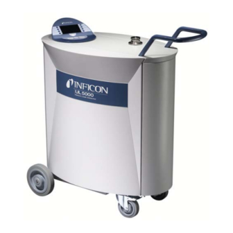
- Page 1 T E C H N I C A L H A N D B O O K iina74e1-h (1408) Translation of the original handbook Catalog-No. 550-500A, 550-501A from software version V 5.14 UL5000 Helium Leak Detector...
-
Page 2: Table Of Contents
General Information Notes on the Use of this Handbook 1.1.1 Safety Symbols 1.1.2 Indications 1.1.3 Symbols of Vacuum Technology 1.1.4 Definition of Terms Support from INFICON Service 1.2.1 Service Centers Introduction 1.3.1 Purpose 1.3.2 Technical Data 1.3.2.1 Physical Data 1.3.2.2 Electrical Data 1.3.2.3... - Page 3 3.2.1 Startup and Measure 3.2.2 Internal Calibration 3.2.3 Verification Description and Working Principle Introduction Components of the UL5000 4.2.1 Vacuum System 4.2.2 Control Panel 4.2.2.1 LC Display 4.2.2.2 START Button 4.2.2.3 STOP Button 4.2.2.4 ZERO Button 4.2.2.5 MENU Button 4.2.2.6 Soft Keys 4.2.2.7...
- Page 4 6.4.5 Alarm delay 6.4.6 Audio alarm type 6.4.6.1 Pinpoint 6.4.6.2 Leak rate prop. 6.4.6.3 Setpoint 6.4.6.4 Trigger alarm Calibration Settings 6.6.1 Vacuum settings 6.6.1.1 Automatic purge 6.6.1.2 Vent delay 6.6.1.3 Vacuum ranges 6.6.1.4 HYDRO•S 6.6.1.5 Leak rate internal test leak 6.6.1.6 Machine factor 6.6.1.7...
- Page 5 9.5.2 4000 hours maintenance 9.5.3 8000 hours maintenance 9.5.4 16000 hours maintenance Description of the maintenance work 9.6.1 Opening the UL5000 Check/Replace the filter cell Replacing the Exhaust Silencer Turbomolecular pump TMH 071 9.10 Scroll Pump Appendix Declaration of Conformity...
-
Page 6: General Information
This technical handbook contains important informations on the functions, instal- lation, start-up and operation of the UL5000. General We reserve the right to modify the design and the specified data. The illustrations are not binding. -
Page 7: Indications
The range of the preamplifier and the vacuum ranges are selected automatically. The autoranging feature of the UL5000 covers the entire range or leak rates depending on the selected operating mode. Not only the leak rate signal, but also the pressure in the test sample (inlet pressure P1) and the fore vacuum pressure (P2) are used for control purposes. - Page 8 Menu The menu allows the user to program the UL5000 according to his requirements. The menu has a tree architecture. Default Status of the UL5000 when supplied by the factory.
-
Page 9: Support From Inficon Service
Support from INFICON Service If an instrument is returned to INFICON or an authorised representative of INFICON, please indicate whether the instrument is free of substances damaging to health or whether it is contaminated. If it is contaminated also indicate the nature of the hazard. -
Page 10: Service Centers
1.2.1 Service Centers In case you urgently need assistance please get in touch with the local INFICON Service in your country or the service hotline in Cologne, Germany: Algeria jhj@agramkow.dk Finland jhj@agramkow.dk Agramkow Phone: +45 741 236 36 Agramkow Phone: +45 741 236 36... - Page 11 Fax: +49 221 56788-9112 Poland kamola@vakpol.com Taiwan Susan.Chang@inficon.com VAK-POL & GAZ Sp. zo.o Phone: +48 60 23 15 212 INFICON Company Limited Phone: +886.3.5525.828 Pulawy Fax: +48 60 23 15 212 Chupei City, HsinChu Hsien Fax: +886.3.5525.829 Portugal leakdetection.service@inficon.com Tunisia leakdetection.service@inficon.com...
-
Page 12: Introduction
INFICON before you send the parts. Caution The UL5000 is to be used for leak detection only. It must not be used as a pumping system (esp. pumping aggressive or humid gases.) General Information... -
Page 13: Technical Data
Run-up time (after starting) Caution To get down to the minimum detected leak rate range some conditions must be fulfilled: • UL5000 has fully warmed up • Ambient conditions must be stable (temperature, no vibration/ accelerations.) • The part under test has been evacuated long enough (background is no longer decreasing) •... -
Page 14: Electrical Data
80% non condensing Max. permissible height above sea level (during operation) 2000 m Unpacking Unpack the UL5000 immediately after delivery, even if it will be installed later on. Examine the shipping container for any external damage. Completely remove the packaging materials. -
Page 15: Supplied Equipment
– Technical Handbook UL5000 – Spare Parts List UL5000 • hooks to wrap power cord (with screws) (see arrow 6) • Tool to open the UL5000 (see arrow 7) • O-Ring with filter (for use at applications with particles) • Tool box (detachable) •... -
Page 16: Accessories And Options
Leak Ware (software package) 14090 1.4.2.1 Sniffer line SL200 By use of the sniffer line the UL5000 can easily be converted to a sniffer leak detector. The length of the sniffer line is 4m (i.e. 12 feet). 1.4.2.2 Toolbox The toolbox is a detachable compartment with a lockable lid. Fittings and small fixtures can be stored plus the hand set (See Chapter 1.4.2.5). -
Page 17: Rc1000 Remote Control
1.4.2.5 RC1000 Remote control The RC1000 is a wireless remote control that allows to operate the UL5000 from distance up to 100 m. It provides the functions START, STOP/VENT, ZERO and speaker volume, and displays leak rate in bargaraph or in chart mode. (see also Technical Handbook RC1000.) -
Page 18: Installation
For transportation the chassis plate where the pump is mounted on has to be secured by a transportation fixing. This transportation fixing consists of 2 screws at chassis of the UL5000 (one on each side). To get access to these screws remove the side covers of the UL5000. - Page 19 Fig. 2-1 For transportation fixing the screws are tightened to the chassis plate. For operation of the UL5000 the screws should be loosened. To loosen the screws first loosen the counter nut that is accessible from underneath: Fig. 2-2 Loosen the screws approximately 10 mm above the chassis plate anf tighten then...
-
Page 20: Working Location
Ensure a sufficient air cooling. The air inlet as well as the air discharge openings must never be obstructed. Caution The UL5000 can be locked by arresting the castors of the front wheels to avoid movements on skewness. Caution Make sure that you can always reach the mains plug. -
Page 21: Electrical Connections
5 depending on the application and gases used. It is recommended that you check all major helium sources in the vicinity of the UL5000 within a radius of about 10 m for the presence of any big leaks. You may use the sniffer probe for this. - Page 22 Danger S TOP Only 3-core mains cables having a protection ground conductor must be used. Operation of the UL5000 where the ground conductor has been left unconnected is not permissible. Tipp The power cord can be secured against coming out by using the power cord fixture as shown: Fig.
-
Page 23: Connections For The Data Acquisition Systems
2.3.2 Connections for the Data Acquisition Systems Accessories Digital Out Digital In Recorder RS232 Remote Control RC1000 / Wireless Transmitter 7. Mains Socket 8. Mains Switch 9. Hole to mount cable hooks. 10. Speaker Vent Purge Fig. 2-6 Connections Tipp The sockets: Accessories, Digital Out, Digital In and Recorder have pin 1 on top. -
Page 24: Accessories
10 W. The contacts are numbered from top to bottom. Assignment +24 V, constantly applied, power supply for the INFICON partial flow valve or sniffer line. GND24 3, 6 Input 4, 5, 7, 8 Output 2.3.2.2... -
Page 25: Digital In
Closed in case recorder output is invalid. Only used when record output is set on „leak rate“. 2.3.2.3 Digital In These inputs can be used to control the UL5000 with a programmable logic control (PLC). Assignment Assignment +24V, bridged with pin 1 Purge of socket „Digital Out“... -
Page 26: Recorder
The chart recorder outputs are electrically isolated from other plugs. If, in spite of this, hum interference is apparent it is recommended to operate the UL5000 and the chart recorder from the same mains phase. If this is not possible, you must make sure that the frame ground of both instruments is kept at the same potential. -
Page 27: Vacuum Connections
Vacuum Connections 2.4.1 Inlet Port The inlet port is located on the top of the UL5000. The size of the flange is DN 25 KF. Warning Risk of injury due to sucking connection flange (inlet port). If the Vacuum-Mode of the UL5000 is activated, the connection flange may suck bodily parts around the connection flange. -
Page 28: Default Parameters
Default parameters The following parameters are set like shown when in the menu of the UL5000 under Settings Parameters saveload, „load default values“ is chosen. Auto-scaling: Scaling logarithmic Display range: 4 decades Time axis: 32 seconds LCD invers: Background in stand by mode:... -
Page 29: First Operation Check
First Operation Check The steps for an initial operation are described in this chapter. It is explained how to switch on the UL5000, how to measure and how to carry out an internal calibration. Notice: If anything unexpected happens during the initial operation or the leak detector acts in a strange way the UL5000 can be switched off by the mains switch at any time. - Page 30 The start up procedure takes about 4 minutes and the end is indicated by a beep. The UL5000 is in Stand-by mode now. Fig. 3-1: Top view of the UL5000 Pos. Description Pos. Description Control Panel Inlet Port Check if the inlet port Fig.
- Page 31 STOP Button Fig. 3-2/13, the UL5000 will go to Stand-by. If you press STOP a few seconds the inlet of the UL5000 will be vented. To finish the startup procedure please proceed with #16. For calibration proceed with First Operation Check...
-
Page 32: Internal Calibration
3.2.2 Internal Calibration Proceed the internal calibration (See Chapter 7.2.1 Internal Calibration). For better quantitative measurements please allow the unit to warm up (15 … 20 minutes). • Press Calibration (Soft Key no. 5 Fig. 3-2/8) to get into the calibration menu. •... -
Page 33: Description And Working Principle
The vacuum is achieved with a pumping system that is part of the UL5000. In addition the vacuum can be generated by pumps with are set up in parallel to the leak detector. - Page 34 Gas molecules getting into the mass spectrometer are ionized by the ion source. These positively charged particles are accelerated into the magnetic field following a circular path, the radius of which depends on the mass-to-charge ratio of the ions. Only helium ions can pass this filter and reach the ion collector where the stream of the ions is measured as a electrical current.
-
Page 35: Control Panel
START Button Pushing the START Button Fig. 4-2/6 enables the UL5000 to start the measure procedure. If the START button is pushed again in measurement mode, the maximum leak rate indicator („hold“ function) is activated. This indicator shows the maximum leak rate between „START“ and next „STOP“... -
Page 36: Stop Button
4.2.2.3 STOP Button Pushing the STOP Button Fig. 4-2/13 interrupts the measure procedure. If the button is pressed longer the inlet is vented according to the conditions defined in the menu Vent delay. See Chapter 6.6.1.2 Vent delay to select the time parameters of the venting. -
Page 37: Menu Button
leak rate leak rate displayed raw signal ZERO > 3 s Fig. 4-4 undo zero When you want to see the raw signal (including underground) please press the ZERO button about 3 seconds. The saved value will be reset to zero. The under- ground signal will not be suppressed anymore. -
Page 38: Numerical Entries
4.2.2.7 Numerical Entries If you have opened a menu page where a number can be changed please proceed in the following way: • If you don’t want to change anything, press Soft Key no. 1 Cancel. The digit that can be changed is displayed inverted. With the arrows (Soft Key •... -
Page 39: Working Modes
Since the scroll pump continues to evacuate the test sample the inlet pressure p will continue to drop. Below 2 mbar the UL5000 will switch to FINE mode, i.e. V1a and V4a will open and valve V1b will close. The gas stream enters the turbo pump at an intermediate level. -
Page 40: Sniffer Mode
Fig. 4-7 (right) regardless the inlet pressure. 4.3.2 Sniffer Mode In sniff mode a sniffer line (preferably the INFICON standard sniffer line 14005) is connected to the inlet port. When pressing the START Button the system starts to pump air through the sniffer line. Due to the constant gas flow through the sniffer line the software will range through GROSS into FINE mode and stay there. -
Page 41: Operation Of The Ul5000
Measure). After about 2.5 min the run-up procedure is finished; the unit is in Stand-by-mode and ready to measure. Please connect the part to be tested to the inlet port and press START. The UL5000 starts to evacuate the part. The evacuation time depends on the volume of the test part. -
Page 42: Purging
5.3.1 Purging Every time when the UL5000 changes into stand by mode it starts purging automa- tically after 20 seconds. During this purging the scroll pump is flushed through purge connection (See Fig. 2-1/11). When the machine is in stand by mode this operation also can be activated manually (Key 7). -
Page 43: Speaker Volume
VAC or SNIFF indicate which working mode was selected (see Chapter Mode). ULTRA • GROSS/FINE/ Depending on the inlet pressure the ULTRA UL5000 may be in GROSS, FINE or ULTRA, which is indicated here (see Chapter 4.3 Working Modes). ZERO • ZERO Indicates if ZERO-function is active. -
Page 44: Numerical Display Mode
Chapter 6.3) you can switch HYDRO•S on or off with softkey 4. If HYDRO•S is on, the status line indicates „HYDRO•S“, if HYDRO•S is off, the status line indicates „VAC“. Also refer to Chapter 6.6.1.4 Notice: In the HYDRO•S mode the lower detection limit is 1 x 10 mbar l/s Operation of the UL5000... -
Page 45: Description Of The Menu
Calibration of the UL5000. Calibration Please refer to Chapter 6.5. Settings of internal machine parameters. Settings Please refer to Chapter 6.6. Information on the UL5000 (electrical and Information vacuum data) and service menu. Please refer to Chapter 6.7. Access restrictions. Access Control Please refer to Chapter 6.8. - Page 46 1. Level 2. Level 3. Level Scale linear/logarithmic Display-range auto/manual Time axis View (See 6.2) Contrast Background in Stand-by Decimal places Lower display limit Mode (See 6.3) Sniff/Vacuum Trigger Level 1 Trigger Level 2 Volume Trigger & Alarms (See 6.4) Units Alarm delay Audio alarm type...
-
Page 47: View
View • Main Menu > View In this menu Fig. 6-3 all features that influence the way data are displayed are put together. Fig. 6-3: The View Menu Key No. Name Description Back Return to the main menu. Settings for bargraph and trend mode. Scale linear/logarithmic Please refer to Chapter 6.2.1. -
Page 48: Display-Range Auto/Manual
6.2.2 Display-range auto/manual • Main Menu > View > Display-range auto/manual The upper limit of the displayed leak rate range can be set manually or automatically. These settings apply to the bargraph (=bar underneath the digital figures in the measurement mode and y-axis in the trend mode). With the upper limit defined here the lower limit is set to a value based on the number of decades ( 6.2.1). -
Page 49: Contrast
If by accident the display has been set too bright or too dark so that it can not be read off, this may be changed as follows: Switch off the UL5000 and turn it on again. During the run-up phase press the key no. 3 or 7 so long until the display can be read properly again. -
Page 50: Decimal Places
When switched to Stand-by / Vent again a new internal background is calculated after 25 s. The updated value is underlined. This means that if you press START when the value is underlined, the actual background signal will be subtracted. If you press START when the value is not underlined, the old background signal from the last Stand-by will be subtracted. -
Page 51: Mode
Mode • Main Menu > Mode The mode menu Fig. 6-4 enables the submenu to select the different working modes. Fig. 6-4: The Mode Menu Key No. Name Description Return to the main menu without any changes Cancel of the present settings. The normal vacuum mode will be used. -
Page 52: Trigger & Alarms
Trigger 1 and Trigger 2 are programmable leak rate levels. If these levels are exceeded some outputs of the UL5000 will react, especially if Trigger 1 is exceeded. Display In the status line of the display the signs for Trigger 1 and Trigger 2 are displayed inverted if the leak rate exceeds (becomes higher than) the programmed value. -
Page 53: Volume
6.4.2 Trigger Level 2 • Main Menu > Trigger & Alarms > Trigger Level 2 The value of the second trigger level can be set. 4.2.2.7 Numerical See Chapter Entries for the description of the entry. If Trigger 2 is exceeded the corresponding relay will switch. This is also indicated at the display. -
Page 54: Units
6.4.4 Units • Main Menu > Trigger & Alarms > Units The preferred leak rate unit can be selected. There is the choice of 4 (mbar, Pa, Torr, atm)pressure units and 5 leak rate units (mbar l/s, Pa m /s-1, Torr l/s, atm cc/s). Notice: In Sniff mode the following measuring units are selectable additionally (Refer to Chapter Chapter 6.3): ppm, g/a eq (helium leak rate is equivalent... -
Page 55: Audio Alarm Type
6.4.6 Audio alarm type • Main Menu > Trigger & Alarms > Audio alarm type The trigger of the audio alarm can be switched on or off. Softkey 2: Pinpoint 6.4.6.1 See Chapter Softkey 3: Leak rate prop. The sound will be proportional to the leak rate signal. 6.4.6.2 See Chapter Softkey 6:... -
Page 56: Setpoint
6.4.6.3 Setpoint The tone is off as long as the leak rate is below the Trigger level 1. Above Trigger 1 the tone varies proportional to the leak rate Fig. 6-7. Fig. 6-7: Setpoint 6.4.6.4 Trigger alarm As soon as the leak rate increases above trigger level 1, a multi-tone signal is gene- rated. -
Page 57: Settings
Switching between helium and hydrogen. See Mass Chapter 6.6.3 Interfaces See Chapter 6.6.4 Miscellaneous See Chapter 6.6.5 Parameter save / load See Chapter 6.6.6 Choose functions of protection of the UL5000 in Monitoring functions with this mode. See Chapter 6.6.6 Description of the Menu... -
Page 58: Vacuum Settings
6.6.1 Vacuum settings • Main Menu > Settings > Vacuum settings This menu allows to observe and to change the settings belonging to the vacuum system. Softkey 2: Automatic purge (Purging) 6.6.1.1 Refer to Chapter Softkey 3: Vent delay Please refer to Chapter 6.6.1.2 Softkey 4: Booster TMP mode Please refer to Chapter... -
Page 59: Vent Delay
Through this menu item it is possible to define the delay time until the inlet port is vented when operating the STOP button. When the STOP button is pressed for a period of time which is shorter than the delay time specified here, the UL5000 will just change to Stand-by mode. -
Page 60: Hydro•S
This setting is only valid, if mass mode is set to „ He“. See Chapter 6.3. Softkey 7: enable If HYDRO•S automatic is enabled, the UL5000 switches HYDRO•S on and off at the following conditions: HYDRO•S is switched on, if •... -
Page 61: Machine Factor
Main Menu > Settings > Zero & Background The kind of background suppression inside the UL5000 and the function of the Zero button can be selected. Softkey 3: Background suppression Refer to Chapter 6.6.2.1 Softkey 4: Calculate inlet area background Refer to Chapter 6.6.2.2... -
Page 62: Background Suppression
Zero & Background > Background Suppression By this mode the internal helium background of the UL5000 will be subtracted at every measurement after pressing START. This function helps to save clean up of the UL5000 after a helium contamination. Softkey 3: Off... -
Page 63: Zero
• Main Menu > Settings > Mass The requested mass of the measured gas can be selected. The UL5000 must be in Stand-by. Softkey 2: H (2 amu) Hydrogen with the mass of 2 amu will be measured. Softkey 3: He (3 amu) Isotope of helium with the mass of 3 amu will be measured. -
Page 64: Interfaces
UL5000 can not be controlled via keyboard. The START, STOP and ZERO button at the machine are deactivated. Softkey 5: Local & PLC The UL5000 is controlled via the Digital In connector or the START, STOP and ZERO buttons at the control panel. Softkey 6: Local & RS232 The UL5000 is controlled via the Digital In connector or the START, STOP and ZERO buttons at the control panel. -
Page 65: Recorder Output
6.6.4.2 Recorder output • Main Menu > Settings > Interfaces > Recorder output The signals to be recorded can be selected in this submenu. Softkey 1: Cancel Return to the previous menu without any changes of the present settings. Softkey 2: Arrow up Adress recorder output 1 or 2 Softkey 3: Arrow down Adress recorder output 1 or 2... -
Page 66: Rs232 Protocol
Output of the measured value in the unit set up, followed by date and time. MEAS: The UL5000 is in the measure mode. When pressing the START button once again in the measure mode or activation of the START input at the DIGITAL IN port the leak rate will be send out. -
Page 67: Scaling Recorder Output
Please execute the function „STORE DATE“ in the operating mode „Single Part Measurement“ for starting the record of the measured values. Softkey 7: ASCII Gives the chance to use the UL5000 via a RS232 terminal. 6.6.4.4 Scaling Recorder Output •... -
Page 68: Miscellaneous
6.6.5 Miscellaneous • Main Menu > Settings > Miscellaneous The actual date and time, the prefered language and the mains frequency can be set in this submenu. Softkey 2: Time&Date See Chapter 6.6.5.1 Softkey 3: Language See Chapter 6.6.5.2 Softkey 4: Leak rate filter See Chapter 6.6.5.3... -
Page 69: Leak Rate Filter
50 Hz for 230 V and 60 Hz for 115 V. Softkey 3: 50 Hz The UL5000 will be run at a mains frequency of 50 Hz. Softkey 6: 60 Hz The UL5000 will be run at a mains frequency of 60 Hz. -
Page 70: Service Message Exhaust Filter
6.6.5.6 Service message exhaust filter The exhaust filter must be maintained at regular intervals to ensure the correct function of the UL5000. If the service message is activated, the UL5000 reminds you of the required maintenance. Softkey 3: Off Softkey 5: Help... -
Page 71: Save Parameter Set
If the calibration request is switched on, a corresponding message will appear when 30 minutes have elapsed after power on or if the temperature of the UL5000 has changed by more than 5 °C (9 °F) since the last calibration. - Page 72 Monitoring functions > Contamination protection If this mode is switched on the UL5000 closes all inlet valves as soon as the measured leak rate exceeds the programmed leak rate. Thus no more Helium gets into the mass spectrometer. Helium that has gotten into the tool under test can be pumped away by the tool pump.
- Page 73 Maximum evacuation time • Main Menu > Settings > Monitoring functions > Maximun evacuation time This menu item is used to define when the gross leak message is to occur. The gross leak detection process operates in two steps and the limits can be adapted as required.
-
Page 74: Information
The list of occurred errors and warnings will be displayed. Softkey 6: Calibration history The carried out calibrations will be listed. Softkey 7: Calibration factors The vacuum diagram of the UL5000 is shown. Here you can see which valves are opend or closed momentarily and more. Softkey 8: Service (See Chapter 6.7.1) -
Page 75: Access Control
Access Control • Main Menu > Access Control In this sub-menu some functions can be assigned to specific users. Fig. 6-13: The Access Control Menu Softkey 2: Access to CAL function 6.8.1 Please refer to Chapter Softkey 3: Access to Trigger&Alarme menu Please refer to Chapter 6.8.2 Softkey 7:... -
Page 76: Access To Trigger&Alarme Menu
> Change Device PIN The access to the UL5000 can be restricted by a Device-PIN. If the Device-PIN is not 0000 the UL5000 will ask for this PIN directly after power on. Without device-PIN the UL5000 does not even switch on the pumps. -
Page 77: Calibration
Although the UL5000 is a very stable instrument a calibration is recommended from time to time to make sure that ambient temperature changes or dirt or other impacts don’t adulterate the measurements. -
Page 78: Internal Calibration
7.2.1 Internal Calibration For internal calibrations the UL5000 differentiates between two possibilities: • If the unit is blanked off or disconnected from any chamber by a valve on the Inlet Port the automatic calibration can be chosen (Soft Key no. 8). - Page 79 After External Calibration (Soft Key no. 8) has been chosen the following messages are displayed and the described actions are required: • Make sure that the test leak is connected and opened. • Check the leak rate printed on the test leak and compare it with the leak rate at the display.
- Page 80 • No action required. Fig. 7-4: External Calibration, Step 4 • No action required. Fig. 7-5: External Calibration, Step 5 • Close the external leak standard and confirm with OK (Soft Key no. 8). Fig. 7-6: External Calibration, Step 6 Calibration...
-
Page 81: Factor Of Calibration - Range Of Values
8). Fig. 7-7: External Calibration, Step 7 • The UL5000 displays the old and the calculated new calibration factor. Fig. 7-8: External Calibration, Step 8 Factor of Calibration - Range of Values To avoid a faulty calibration the factor of calibration is tested for plausibility at the end of the calibration routine: When the new factor of calibration is not considerably higher or lower (<... -
Page 82: Error And Warning Messages
In some cases it may be helpful to check some settings or measured values before the UL5000 restarts. Therefore it is also possible to press „Menu“ (key no. 4 or Menu key) to enter the UL5000 menu. After leaving the menu the same error message will be displayed again. -
Page 83: List Of Errors & Warnings
List of Errors & Warnings The following pages contain a list of all errors and warnings displayed at the control panel. Warning messages are indicated by numbers with a leading W. Error messages are indicated by numbers with a leading E Displayed Message Description and possible solutions W15 Leak rate is too high! Machine... - Page 84 W45 Emission for cathode 1 can Signal MSIBE on MSV board is not active. Emission for cathode 1 can not not be switched on! be switched on. UL5000 switches to cathode 2. Please order a new ion source. W46 Emission for cathode 2 can Signal MSIBE on MSV board is not active.
- Page 85 Displayed Message Description and possible solutions E47 Emission for both cathodes Signal MSIBE on MSV board is not active. Emission can not be switched can not be switched on! on. Exchange the cathode by changing the ion source. After having exchanged the ion source it must be possible to switch on both cathodes manually via the service menu.
- Page 86 "Frequency converter is faulty", too high! "Booster-TMP is faulty", E73 Emission off (p2 too high) PV >> 0.2 or 3 mbar due to an inrush, e. g. The UL5000 will again try to resume the measurement mode. W76 Maximum of evacuation time •...
- Page 87 Displayed Message Description and possible solutions W83 All EEPROM parameter lost. • EEPROM on back plane is empty and was initialized with default Please check your settings. valves. Enter all parameters again. • The EEPROM might be faulty when warning comes up again after power up.
-
Page 88: Maintenance Works
A maintenance contract is recommended. When it is time to maintenance the machine after 1500/4000/8000 hours it will be shown as a warning message at the display of the UL5000. The message will be displayed until the maintenance rate is met. -
Page 89: Inficon Service
INFICON Service If equipment is returned to INFICON, indicate whether the equipment is free of subs- tances damaging on health or whether it is contaminated. If it is contaminated also indicate the nature of the hazard. For this you must use a Declaration of Contami- nation form Fig. -
Page 90: Maintenance Plan
Maintenance Plan Required maintenance Operation hours/Years Repair level Assembly UL5000 1500 4000 8000 16000 Part no. Vacuum system Scroll pump IWATA Exchange the scrollmodule 200000021R ISP 500 Scroll pump Varian Exchange the Tip Seal 200001671 TS 620 Exchange the scrollmodule... -
Page 91: Maintenance Groups
Maintenance groups The maintenance plan for the UL5000 can be subdivided in 4 maintenance groups. • 1500 hours maintenance • 4000 hours maintenance • 8000 hours maintenance • 16000 hours maintenance 9.5.1 1500 hours maintenance The 1500 hours maintenance can be performed by an operator or a maintenance person. -
Page 92: 4000 Hours Maintenance
9.5.2 4000 hours maintenance The 4000 hours maintenance should be performed by an INFICON service tech- nician or another authorised person at least yearly. Independently of 4000 working hours the lubricant reservoir of the Turbomolecular pump and the oil in the Fore pump should be replaced at least yearly. -
Page 93: 8000 Hours Maintenance
After 8000 working hours, the „Tip Seal“ of the scroll module of the Varian pump should be replaced by an INFICON service technician. If the „Tip Seal“ has not been replaced, then after 12000 working hours the scroll module must be exchanged. -
Page 94: 16000 Hours Maintenance
9.5.4 16000 hours maintenance The 8000 hours maintenance should be performed by an INFICON service tech- nician or an other authorized person. After 16000 working hours the bearing of the turbo pump and the different kind of fore pump will reach their expecting life time. -
Page 95: Description Of The Maintenance Work
Description of the maintenance work Only trained specialist staff can performe more changes at the UL5000 than the normally maintenance work. Danger S TOP The protective conductor screw at the chassis plate should not be loosened. The operator is not protected against electric shock by working without a protective conductor line. -
Page 96: Check/Replace The Filter Cell
Wedge (Accessories). Required material Spare Filter cell P/N 200000685 Danger S TOP Disconnect the power cord from the UL5000 before opening one of the side covers. • Please refer to section 9.6.1 to open the unit. • Catch the filter cell by using your two fingers ( Fig. - Page 97 Notice: The white surface of the filter cell which is marked with „clean air side“ must show towards the fans. • Push the filter cell into the guide plate and close the UL5000 by pressing the side cover. Maintenance works...
-
Page 98: Replacing The Exhaust Silencer
Replacing the Exhaust Silencer Required material Exhaust silencer P/N 20099183 • Switch off the UL5000. • Unscrew the exhaust filter from the exhaust. Screw the new exhaust filter onto the thread of the exhaust and tight it. Fig. 9-3 Replacing the exhaust silencer Pos. -
Page 99: Turbomolecular Pump Tmh
The PFEIFFER turbomolecular pump requires a maintenance annually or every 4000 working hours. Please refer to the PFEIFFER operating instructions PM 800 504 BN/F and PT 0017 BN/B for more detailled informations. The maintenance work should be performed by the INFICON service or an authorized INFICON service partner. 9.10... -
Page 100: Appendix
Appendix Accessories Hand Set alarm Helium leak rate Ambient temperature Humidity Audio alarm Automatic Internal Calibration I CAL INFICON Service background information built-in leak standard Inlet area background suppression Inlet port Inlet pressure Calculate Inlet Area Background Installation calibration Ion source... - Page 101 Pinpoint STOP Button Power Storage temperature • consumption • supply pressure Temperature Protection • ambient • Type of • storage Pumping speed time axis Purge Time&Date Purging Transportation Purpose trend mode Trigger Trigger alarm QT100 turbo pump turbomolecular pump Type of protection Recorder Relay Output RS232...
-
Page 102: Declaration Of Conformity
Declaration of Conformity Declaration of Conformity... - Page 103 Declaration of Conformity...
- Page 104 INFICON GmbH, Bonner Strasse 498, D-50968 Cologne, Germany UNITED STATES TAIWAN JAPAN KOREA SINGAPORE GERMANY FRANCE UNITED KINGDOM HONG KONG Vi sit o ur we bsi t e fo r con t act i nfo rm ati on an d o t her sal es o ffice s wo rl dw id e. w w w . i n f i c o n . c o m...
- Page 105 Declaration of Conformity...
- Page 106 Bilder/transportation lock 3.JPG @ 300 dpi Bilder/mains switch.jpg @ 300 dpi Bilder/euro mains switch.jpg @ 200 dpi Bilder/connections.tif @ 200 dpi Bilder/top view.drw Bilder/control panel.drw Bilder/ul5000 vacuum diagram.drw Bilder/control panel.drw Bilder/falling background.drw Bilder/absolut measurement.drw Bilder/numerical entry step1.png @ 150 dpi Bilder/UL5_trigger_level_1_sub.png @ 150 dpi Bilder/Evacuation.png @ 300 dpi...
- Page 107 Bilder/UL5_CAL_press_OK_stable.png @ 150 dpi Bilder/UL5_CAL_complete.png @ 150 dpi Bilder/exclamation mark.WMF Bilder/open ul5000.drw Bilder/change filter_chassis.drw Bilder/change silencer.drw Bilder/ul5000.07.06.2011.engl.pdf...
Need help?
Do you have a question about the UL5000 and is the answer not in the manual?
Questions and answers