Inficon HLD6000 Installation Manual
Leak detector
Hide thumbs
Also See for HLD6000:
- Original operating instructions (76 pages) ,
- Translation of the original operating instructions (90 pages)

Related Manuals for Inficon HLD6000


Summary of Contents for Inficon HLD6000
- Page 1 Translation of the original operating instructions HLD6000 Leak detector Order no.: 510-025, 510-027, from software version: 510-028 1.11...
- Page 2 No part of this manual may be reprinted, translated or duplicated without the expressed written consent of INFICON GmbH.
-
Page 3: Table Of Contents
Table of Contents About these instructions ............................7 Target groups ................................. 7 Other applicable documents ............................ 7 Displaying information ............................... 7 1.3.1 Warnings ..................................7 Safety ....................................9 Intended use ................................... 9 Owner requirements ..............................9 Operator requirements .............................10 Dangers ..................................10 Shipment, Transport, Storage ..........................11 Description ..................................13 Function ..................................13... - Page 4 6.3.6 Set time interval for calibration request ......................36 6.3.7 Switching the request for replacing filters on or off ..................36 6.3.8 I/O module ..................................36 6.3.8.1 Create a connection between the device and the I/O module ..............36 6.3.8.2 Configuring analog outputs ...........................
- Page 5 8.1.2 Cleaning the calibration opening .........................62 8.1.3 Replacing the fuses ..............................62 8.1.4 Cleaning the device ..............................62 Sniffer line ..................................63 8.2.1 Replacing the filter holder ............................63 8.2.2 Changing the filter block ............................64 Sending for maintenance or repairs ........................64 Decommissioning the device ..........................65 Disposing of the device ............................65 Sending in the device ..............................65 Appendix ..................................67...
- Page 6 Table of Contents...
-
Page 7: About These Instructions
This document applies to the software version stated on the title page. Target groups These operating instructions are intended for the operator of the HLD6000 leak detector and for technically qualified personnel with experience in leak detection technology. Other applicable documents Interface description, document no. - Page 8 1 About these instructions...
-
Page 9: Safety
The device is a leak detector for sniffer leak detection. Use the device to locate and quan- tify leaks on test objects. The HLD6000 sniffs for different gases depending on which sniff- er line is connected. The following sniffer lines are available: ... -
Page 10: Operator Requirements
► If you have any questions regarding operation or maintenance that you cannot find answers to in these instructions, please contact INFICON customer service. Dangers The device was built according to the state of the art and the recognized safety regula- tions. -
Page 11: Shipment, Transport, Storage
Shipment, Transport, Storage Table 1: Shipment Shipment Item Quantity HLD6000 (Basic unit) Sniffer line with sniffer tip (100 mm) Power supply cable (EU and US version) Fuses Filter holder for sniffer tip Filter blocks for sniffer tip Operating instructions Interface description USB stick with instructions, software ►... - Page 12 3 Shipment, Transport, Storage...
-
Page 13: Description
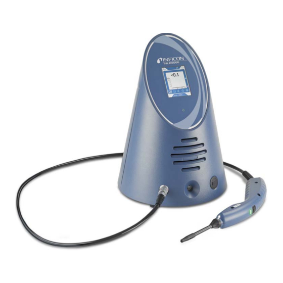
Function The HLD6000 comprises of a basic unit and a sniffer line. The HLD6000 can, depending on the model, verify and quantify gases sucked in by the sniffer line with the help of an infrared gas analyzer. The key assemblies of the HLD6000 are: ... -
Page 14: Basic Unit
Basic unit The basic unit is only called a “device” in the following as long as the meaning remains clear. Fig. 1: Frontal view Touch screen USB port LED power indicator Calibration opening for internal calibration Speaker Sniffer line connection port b LED power indicator Operating display with 3 statuses: –... - Page 15 Mains plug The mains plug is used to switch the device on and off. b M12 socket, 8-pin – For connection of the INFICON I/O module, available as an accessory see "6.3.8 I/O module", page – Length of the data cable: Max. 30 m...
-
Page 16: Sniffer Line
Fig. 3: View from below Rating plate with information regarding COOL-Check calibration leak behind the cover supply voltage, serial number and productio date. Filter plates Sniffer line You need a sniffer line to operate the device. There are sniffer lines for verification of a sin- gle gas or sniffer lines for the verification of several gases see "2.1 Intended use", page 9 see "10.1 Accessories and spare parts", page... -
Page 17: Technical Data
Fig. 4: Handle: Display and functions Illumination LED Status LED Sniffer tip Name of gas or sniffer line If the setpoint is exceeded, the display switches from green to yellow, see Table 7 on Page You can also set the illumination LEDs to flash at the lower end of the sniffer probe, "6.4.2 Setting up the sniffer probe", page Technical data Table 2: Technical data... - Page 18 Table 2: Technical data (Contin.) Electrical data Supply voltages and frequencies 100 … 240V 50/60 Hz Power consumption 55 VA Protection class IP 30 Overvoltage category Mains fuse 2 x 1 A slow-blowing (Ø 5 × 20 mm) Power supply cable 2.5 m (8.2 ft.) Length of the data cable on the M12 plug Max.
- Page 19 Table 3: General factory settings (Contin.) Error information operator No. and text Error information supervisor No., text and info Filter change request Gas in the SMART sniffer line R134a I/O module protocol ASCII Interval for auto standby 2 min. Interval for calibration request 60 min.
- Page 20 Table 3: General factory settings (Contin.) Language English Value axis decades Value axis grid Linear Time axis scale 30 s Table 4: Factory settings for access authorization Parameter Access Ctrl. Analog output upper limit Supervisor Display off after Operator Display brightness Operator Display maximum value (log.) exponent Operator...
- Page 21 Table 4: Factory settings for access authorization (Contin.) Memory location Operator Language Operator Time Supervisor Value axis decades Operator Value axis grid Operator Time axis scale Operator 4 Description...
- Page 22 4 Description...
-
Page 23: Installation
Installation Setup Danger from moisture and electricity Moisture penetrating the device can lead to personal injury from electric shocks and to material damage from short circuits. ► Only operate the device in a dry environment. ► Operate the device away from sources of liquid and moisture. Material damage from overheated device The device heats up during operation and can overheat without sufficient ventilation. -
Page 24: Sniffer Tip
5 Attach the new sniffer line. You can switch the device back on again. Sniffer tip 5.3.1 Replacing the sniffer tip Material damage from pollution Particles in the air intake can destroy the sniffer line. Always switch off the device before every installation! ►... -
Page 25: Using The Water Conservation Sniffer Tip
"10.1 Acces- sories and spare parts", page In addition to the rigid sniffer tip what comes delivered with the HLD6000 you can also use a 400 mm long flexible tip. By bending the flexible tip accordingly, hard-to-reach areas can also be accessed. -
Page 26: Using An Extension Hose For A Sniffer Tip
5.3.4 Using an extension hose for a sniffer tip To get into hard-to-reach areas, attach an extension hose to the sniffer tip, see "10.1 Ac- cessories and spare parts", page Fig. 7: Attach the extension hose Filter holder on the sniffer tip Release ring Short extension hose Extension hose... -
Page 27: Connecting To The Power Supply System
The USB stick must be formatted in the FAT file system. Connecting a PC Connection is done using the I/O module, see "10.1 Accessories and spare parts", page Please refer to the “Interface description HLD6000” (doc. no. kins44e1-a) for further infor- mation on data exchange. 5 Installation... - Page 28 5 Installation...
-
Page 29: Operation
Operation Switching on the device Connect a sniffer line and switch on the device. The device will start up and, after a short time, display "Importing data". Fig. 9: The device starts up In order to switch to English from another language, press "EN" on the depicted window. After the run-up, the device will measure the leakage rate on the sniffer line. -
Page 30: Operating The Device
Operating the device 6.2.1 Structure of the touch screen The display primarily works with symbols. Four symbols are always shown on the display: the navigation keys . You also see other symbols and elements see "Table 6: Function keys", page 31 depending on the context. - Page 31 Table 5: Navigation keys (Contin.) – Symbol for information – Display information regarding the device such as the software version, operating hours, serial num- ber, date and time – Navigate back to the previous information layer – Symbol for diagnosis –...
-
Page 32: Measurement Display Elements
6.2.2 Measurement display elements The measured leakage rates are displayed numerically and with a linearly subdivided graph. Exceeding the setpoint which is set up is illustrated in color, see "6.4.1 Setting set- points", page The following diagram shows additional elements relating to the measurement display: Fig. -
Page 33: Display On The Sniffer Line
6.2.3 Display on the sniffer line An LED is mounted on the sniffer handle where you can read the different operating modes, see Table 7 on Page Fig. 12: Sniffer line display Calibration key, see "6.4.6.1 Time and type of calibration", page 43 Status LED Filter holder on the sniffer tip Designation of the gas that the sniffer line sniffs. -
Page 34: Basic Settings
Basic settings To get an overview of the available options, look at the illustration of the menu trees Overview see "10.2 Menu trees", page You can either carry out your own changes or keep the factory settings, see Table 3 on Page 18 see Table 4 on Page ... -
Page 35: Setting Auto Standby
Screen touch tone Three possible settings: Off, Soft, Loud. ► To adjust the volume, select " > Volume". Alternatively, when on the touch screen select the button 6.3.4 Setting auto standby As well as having the option to manually switch over into standby mode (see "6.5 Stand- by", page 49), it is also possible to set up an auto standby function. -
Page 36: Set Time Interval For Calibration Request
To create the connection between the I/O module and the device, do the following: 1 Switch the device off. 2 Connect the INFICON I/O module with a data cable to the M12 socket on the rear of the device, see "Fig. 2: Rear view", page 3 Switch on the HLD6000. -
Page 37: Configuring Analog Outputs
1000 g/a using the keys. 6.3.8.4 Setting up the I/O module protocol Refer to "Interface description HLD6000 (doc. no. kins44e1-a)" for switching between "ASCII", "LD" (Leak Detection), "Normal" and "Simple" formats. 1 Select " > Set up > Interfaces > I/O Module > Protocol". -
Page 38: Configuring Plc Inputs
3 Choose between "Normal" or "Inverse". 4 Assign additional PLC outputs to a function if necessary. 5 Confirm your selection using 6.3.8.6 Configuring PLC inputs You can set which function is carried out by a signal on the PLC input. 1 Select "... -
Page 39: 6.3.10 Access To The Settings
To cancel protection again, enter “0000” as the PIN (factory setting). If you have forgotten the supervisor PIN, then please contact the INFICON service team. Further information can be found from the help text when entering the PIN. -
Page 40: 6.3.10.3 Changing Parameter Access Levels
6.3.10.3 Changing parameter access levels You are logged in as a "supervisor" 1 Select “ > Parameter > Parameter Access Level". A list of all parameters is shown including the assignments to "supervisor" and "opera- tor". 2 To change a parameter assignment in the list illustrated, press on an entry when logged in as "supervisor".... -
Page 41: Settings For The Measurements
Settings for the measurements 6.4.1 Setting setpoints By setting a setpoint, you decide what quantity of gas lost should be tolerated with a test object. You can set two setpoints on the device. You can use setpoint 1 to, for example, find "very good"... -
Page 42: Setting Up The Gas For The Smart Sniffer Line
User-defined gases You can set up 3 additional gases of your choice, provided that these can be verified by the device. You can obtain more information about this from INFICON by request. There are various options available for setting up. -
Page 43: Verifying R290 With The Sniffer Line For R600A/R290
For most gases the required calibration factors from INFICON can be used. 1 To freely select a gas, select " > Gas" and then set up "User 1", "User 2" or "User 3". -
Page 44: Calibration With An Internal Cool-Check
The gas that leaks from the calibration leak is carried away by strong air currents. Keep this in mind when, for example, a fan blower is standing in your surroundings. Strong air cur- rents provide false results when calibrating. If you have assembled an extension hose for the sniffer tip then before calibrating with the internal COOL-Check insert a centering ring to make the calibration opening on the device smaller see "5.3.4 Using an extension hose for a sniffer tip", page... -
Page 45: Calibration With An External Calibration Leak
6.4.6.3 Calibration with an external calibration leak The gas that leaks from the calibration leak is carried away by strong air currents. Keep this in mind when, for example, a fan blower is standing in your surroundings. Strong air cur- rents provide false results when calibrating. -
Page 46: Measuring
6.4.7 Measuring Risk of electric shock Electrical voltages can be transmitted via the sniffer probe and cause damage to proper- ty or personal injury. ► Do not touch live parts with the sniffer probe. ► Disconnect electrically operated test objects from the mains before starting the leak test and secure them against being restarted without authorization. -
Page 47: Measured Data
► If you have activated the key function on the sniffer probe, see "6.4.2 Setting up the sniffer probe", page 41, the you have the following options: – If the button is not pressed on the sniffer probe: Measurement takes setpoint 1 into consideration, –... -
Page 48: Evaluating Measured Data
A file with measured date is constructed as follows: For example // Record file: \L0000001.txt // Created by HLD6000CU V0.11.02.18681 // HLD6000CU Ser.-No.: 00000000000 // HLD6000 Ser.-No.: 00000000000 // HLD6000MB V0.22.06(1.04.00) // Probe V1.00 // Probe Ser.-No.: HLD5000 probe // Probe Type: SMART (R134A)... -
Page 49: Deleting Measured Data
> Active Warnings". Service The Service menu is password-protected. You can configure settings in the Service menu only after completing a special training course from the INFICON service department. Histories To receive information on errors and warnings which have occurred, select "... -
Page 50: Parameter List
3 View the desired information. These include, for example – under "Basic Unit" there is information regarding the software version, the serial number of the device, the operating hours and the interior housing temperature, – under "COOL-Check" there is information regarding the leakage rate depending on temperature and on the remaining time of use available, –... -
Page 51: Updating The Software
Updating the software Software updates from INFICON are installed with the aid of a USB stick. The update func- tion of the device can be found under " > Update". An update is possible, ... -
Page 52: Updating The Software Of The Basic Unit
Data loss due to an aborted connection Do not switch off the device and do not remove the USB stick whilst the software is ► being updated. ► Switch the device off and back on after a software update has taken place. 6.8.1 Updating the software of the basic unit The software is included in the file named Flash_HLD6000_Main_Vxx.xx.xxx.bin. -
Page 53: Updating The Software Of The Sniffer Line
6.8.3 Updating the software of the sniffer line The software on the HLD6000 sniffer line can be updated from the basic unit provided that the sniffer line is connected and works perfectly. The software is included in the file named "Flash_HLD6000_Probe_Vxx.xx.xxx.bin". - Page 54 6 Operation...
-
Page 55: Warning And Error Messages
– If the problem still exists, contact INFICON customer service. E131 Wrong parameter in the sniffer line The parameters saved in the sniffer line are wrong. Contact INFICON customer service. E132 Old sniffer line not supported An old sniffer line is connected which is not support- Use a current sniffer line. - Page 56 (separate and reconnect; try another sniffer line, if possible). – If the problem still exists, contact INFICON customer service. E135 Checksum error when communicating – The interface to the sniffer line does not function – Check the connection of sniffer line to basic unit with the sniffer line reliably.
- Page 57 – Optical cell is contaminated with water vapor. – Depending on the quantity of water inside the opti- cal cell, let the HLD6000 run between 1 minute and – The optical cell is dirty two hours to clean the optical cell.
- Page 58 – Check the connection of sniffer line to basic unit (separate and reconnect; try another sniffer line, if possible). – If the problem still exists, contact INFICON customer service. W544 Valve does not switch back and forth Internal defect on the sniffer line –...
- Page 59 – Clean the ventilation openings or replace the filter plates. – Contact INFICON customer service. E711 Motherboard temperature is far too high – The ambient temperature is too high. – Switch off the device and allow it to cool down.
- Page 60 7 Warning and error messages...
-
Page 61: Maintenance
Maintenance Carry out maintenance work on the device in accordance with the following description. Life threatening hazard from electric shock Considerable voltages arise inside the device. Touching parts where electrical voltage is applied can result in death. Disconnect the device from the power supply prior to any maintenance work. Make ►... -
Page 62: Cleaning The Calibration Opening
Life threatening hazard from electric shock Switch off the device and disconnect from the mains. 2 Carefully turn the basic unit onto its side. 3 Loosen both screws in the middle of the filter holder, see Fig. 15 on Page 4 Remove the filter plates. -
Page 63: Sniffer Line
Sniffer line Two filters are built into the sniffer line of the device: Filter holder with fine filters in the sniffer tip, Filter block with fine filters at the base of the sniffer tip. Fig. 16: The filters in the sniffer line Filter block Sniffer tip Guide pin... -
Page 64: Changing The Filter Block
"10.1 Accessories and spare parts", page 67 Sending for maintenance or repairs You can send your device to INFICON to have it maintained or repaired. For further infor- mation regarding this topic see "9.2 Sending in the device", page... -
Page 65: Decommissioning The Device
Decommissioning the device Disposing of the device The device can be disposed of by the operator or sent to INFICON. The device is made of recyclable materials. You should use this option to avoid waste and to protect the environment. - Page 66 This form can be downloaded Copies: from our website. Original for addressee - 1 copy for accompanying documents - 1 copy for file of sender INFICON GmbH Bonner Str. 498,50968 Cologne, Germany zisa01e1-b (1106) Tel: +49 221 56788-112 Fax: +49 221 56788-9112 www.inficon.com leakdetection.service@inficon.com...
-
Page 67: Appendix
Appendix 10.1 Accessories and spare parts Table 11: Accessories, spare parts, order no. Order no. Basic unit Filter plate 133x55x3mm, 10 units 200 005 506 Sniffer line R744 (CO 511-045 R600a/R290 511-048 SMART (gas family of the HFC refrigerant) 511-047 Sniffer tip 100 mm long, rigid, includes 6 filter holders and 5 filter blocks 511-021... -
Page 68: Menu Trees
10.2 Menu trees Pressing the navigation key brings you back to the measurement display regardless of whether you were previously in a menu or sub-menu. Table 12: Menu tree "Settings" Setpoints Leakage rate setpoint 1 Setpoint alarm Leakage rate setpoint 2 Display settings Value display Value axis... - Page 69 Table 13: Menu tree "Information" Basic unit COOL-Check I/O module Parameter list Sniffer line Operating unit Bus module Table 14: Menu tree "Diagnosis" Active warnings Service Enter Service PIN Histories Error and warning history Calibration history Update Basic unit Operating unit Sniffer line I/O module 10 Appendix...
-
Page 70: Ce Declaration Of Conformity
10.3 CE Declaration of Conformity 10 Appendix... - Page 71 10 Appendix...
- Page 72 10 Appendix...
-
Page 73: Index
Index Access control 39 Menu trees 68 Access rights 39 Accessories and spare parts 67 Adjust volume 34 Operator requirements 10 Optical cell 13 Owner requirements 9 Basic settings 34 Parameter access levels 20, 40 Calibration 43 Parameter list 50 Calibration - COOL-Check 44 PIN assign 39 Calibration - external calibration leak... - Page 74 Index...
- Page 76 INFICON GmbH, Bonner Strasse 498, D-50968 Cologne, Germany leakdetection@inficon.com UNITED STATES TAIWAN JAPAN KOREA SINGAPORE GERMANY FRANCE UNITED KINGDOM HONG KONG Vis it our web si te fo r co nta c t in fo r ma t io n a nd o t her s a l e s of f ices wo r ld wi de. w w w.i nf ico n.co m...
Need help?
Do you have a question about the HLD6000 and is the answer not in the manual?
Questions and answers