VeriFone VX670 Installation Manual
Hide thumbs
Also See for VX670:
- Installation manual (62 pages) ,
- User manual (37 pages) ,
- Brochure (2 pages)
Table of Contents
Advertisement
Advertisement
Table of Contents

Related Manuals for VeriFone VX670


Summary of Contents for VeriFone VX670
- Page 1 Installation Guide VeriFone Part Number 24003, Revision A.3...
- Page 2 VeriFone, Inc. The information contained in this document is subject to change without notice. Although VeriFone has attempted to ensure the accuracy of the contents of this document, this document may include errors or omissions. The examples and sample programs are for illustration only and may not be suited for your purpose.
-
Page 3: Table Of Contents
ONTENTS ........5 R E F A C E Audience. - Page 4 VeriFone Cleaning Kit ........
-
Page 5: Preface
4, Maintenance. Explains how to maintain your V 670 terminal. Chapter VeriFone Service and Support. Provides information on contacting your local VeriFone representative or service provider, and information on how to order accessories or documentation from VeriFone. Chapter Troubleshooting Guidelines. Provides troubleshooting guidelines, should you encounter a problem in terminal installation and configuration. -
Page 6: Conventions And Acronyms
You must install a roll of thermal- book titles or emphasis. sensitive paper in the printer. The courier type face is Courier http://www.verifone.com used while specifying onscreen text, such as text that you would enter at a command prompt, or to provide an URL. - Page 7 Micromodule-Size Security Access Module PIN-Entry Devices Personal Identification Number RJ45 Registered Jack 45 RS-232 Recommended Standard 232 Security Access Module Subscriber Identity Module UART Universal Asynchronous Transmitter/Receiver Universal Serial Bus VeriFone Part Number Wi-Fi Wireless Fidelity 670 I NSTALLATION UIDE...
- Page 8 REFACE Conventions and Acronyms 670 I NSTALLATION UIDE...
-
Page 9: Hapter
670 terminal is a portable, battery-powered device that uses wireless technologies, including Wi-Fi with 802.11g technology and GSM/GPRS. It also features a 128-by-128 pixel display and a speedy thermal printer. VeriFone ships variants of the V 670 terminal for different markets. Your terminal NOTE may have a different configuration. -
Page 10: Features And Benefits
32-bit processing and multi-tasking Security architecture meets • • capabilities. specifications for PCI-PED and sophisticated file authentication. USB support for VeriFone peripheral Max UI design provides large display • • devices. on small footprint. Backward compatibility with Designed to meet the needs of •... -
Page 11: True Multi-Application Capability
Innovative design resists spills by forcing liquid down and off the front of the terminal • Integrated PINpad offers added convenience to handle PIN-based applications. • Uncompromising reliability from VeriFone, the worldwide leader in e-payment. • Complies with RoHS (Restriction of Hazardous Substances) directive of the European Union. True Multi- •... - Page 12 ERMINAL VERVIEW Features and Benefits 670 I NSTALLATION UIDE...
-
Page 13: H A P T E R Terminal Setup
HAPTER Terminal Setup This chapter describes the terminal setup procedure. You will learn about: • Selecting Terminal Location. • Unpacking the Shipping Carton. • Examining Terminal Features. • Examining the Handy-Link Connector. • Establishing Telephone Line Connections. • Installing the Paper Roll. -
Page 14: Environmental Factors
670 terminal comes equipped with tamper-evident labels. If a label or component appears damaged, please notify the shipping company and your VeriFone representative or service provider immediately. Save the shipping carton and packing material for future repacking or moving the terminal. -
Page 15: Examining Terminal Features
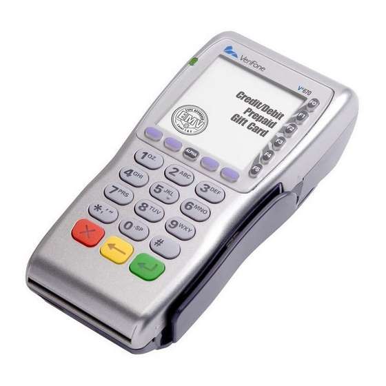
ERMINAL ETUP Examining Terminal Features Examining Before you continue the installation process, notice the features of the Terminal 670 terminal (see Figure Features INTERNAL THERMAL PRINTER (AT THE BACK) INDICATOR LED ATM-STYLE FUNCTION KEYS MAGNETIC CARD TERMINAL DISPLAY READER PROGRAMMABLE FUNCTION KEYS ALPHA KEY TELEPHONE-STYLE... - Page 16 The V 670 terminal contains MSAM cardholders to support multiple stored-value card programs or other merchant card requirements. VeriFone ships variants of the V 670 terminal for different markets. Your terminal NOTE may have a different configuration. The following devices may or may not be present: a smart card reader, or zero or three MSAM cardholders.
-
Page 17: Examining The Handy-Link Connector
ERMINAL ETUP Examining the Handy-Link Connector Examining the The Handy-Link connector is a cell phone style connector that supports a wide Handy-Link variety of communication ports via cable adapters. Connector CELL PHONE STYLE CONNECTOR USB HOST SERIAL PORT (COM 1) USB DEVICE Figure 3 The V... -
Page 18: Usb Connection
ERMINAL ETUP Examining the Handy-Link Connector USB Host A 2-Wire USB Host port for external peripherals. A connector adaptor provides for standard USB host connection. USB Device A 2-Wire USB device port connected directly to the PC’s USB ports. This port is mainly for debugging purposes. -
Page 19: Establishing Telephone Line Connections
ERMINAL ETUP Establishing Telephone Line Connections USB Dongle – Modem A modem in the form of a USB dongle is provided with the V 670 terminal. The USB Dongle – Modem provides communication via a telephone line at speeds of up to 14,400 bps. -
Page 20: Installing The Paper Roll
Poor-quality paper can jam the printer and create excessive paper dust. To order CAUTION high-quality VeriFone paper, refer to Accessories and Documentation. Store thermal paper in a dry, dark area. Handle thermal paper carefully: impact, friction, temperature, humidity, and oils affect the color and storage characteristics of the paper. - Page 21 ERMINAL ETUP Installing the Paper Roll Lift the printer cover up and back. Figure 7 Opening the Printer Cover Remove any partial roll of paper in the printer tray by lifting it up (see Figure Loosen the glued leading edge of the paper or remove the protective strip from the new roll of paper.
- Page 22 ERMINAL ETUP Installing the Paper Roll Drop the paper roll into the printer tray. Figure 9 Loading Paper Roll Pull paper up past the glue residue from the printer tray. Close the paper roll cover by gently pressing directly on the cover until it clicks shut, allowing a small amount of paper past the glue residue to extend outside the printer door.
-
Page 23: Installing/Replacing Msam Cards
Cards CAUTION Observe standard precautions when handling electrostatically sensitive devices. Electrostatic discharges can damage this equipment. VeriFone recommends using a grounded anti-static wrist strap. To Install/Replace Place the terminal upside down on a soft, clean surface to protect the lens MSAMs from scratches. -
Page 24: Installing/Replacing Sim Card
ERMINAL ETUP Installing/Replacing SIM Card (GSM/GPRS Models) Install an MSAM card by aligning the card and carefully sliding it within the guides on the cover until it is fully inserted (see Figure 12). The MSAM card holders are labeled MSAM1, MSAM2, and MSAM3. Figure 12 Installing MSAM Card Before inserting the MSAM card, position it as shown in... -
Page 25: Connecting The Terminal Power Pack
ERMINAL ETUP Connecting the Terminal Power Pack Insert the SIM into the cardholder. NOTE There is only one SIM slot, but there are multiple SAM slots. Make sure you insert the SIM card into the SIM slot, as shown in Figure Figure 14 Inserting SIM Card... -
Page 26: Using The Smart Battery
When the terminal has power, the terminal lights are activated and the LED indicator remains lit. If an application is loaded in the terminal, it starts after the initial VeriFone copyright screen and usually displays a unique copyright screen. If no application... -
Page 27: Smart Battery Features
ERMINAL ETUP 670 Battery Behavior (No Power Cord) Standard Battery Pack The standard battery has a capacity of 1250mAh. It is suited for WiFi and pay-at- table applications where frequent charging is required. High-Capacity Battery Pack The high-capacity battery pack is larger than the standard battery pack and is more suitable for GPRS/CDMA applications. -
Page 28: Manual Shutdown
When the terminal has power, the terminal lights are activated and the green LED indicator remains lit. If an application is loaded in the terminal, it starts after the initial VeriFone NOTE copyright screen and usually displays a unique copyright screen. If no application... -
Page 29: Removal
ERMINAL ETUP Charging the Smart Battery Removal To remove the V 670 smart battery, press the locking tab and pull the smart battery from its slot. Figure 17 Detaching the Smart Battery from the V 670 Terminal Charging the After unpacking your V 670 terminal, install the battery and connect the power Smart Battery pack to the unit for 6 hours. -
Page 30: Using The V X 670 Base Station
ERMINAL ETUP Using the V 670 Base Station Using the V The primary purpose of the Base Station is to charge the terminal battery and Base Station provide a docking station for the terminal after being used in pay-at-table environments. The Base Station can be positioned on a countertop or mounted to the wall. -
Page 31: Powering Up The Base Station
ERMINAL ETUP Using the V 670 Base Station For more information on charging the spare battery on the Full-Featured Base Station and connecting external dongles to the USB ports, see Charging the Spare Battery on the Base Station Attaching the USB Dongles to the Base Station. -
Page 32: Placing The V X 670 Terminal Onto The Base Station
ERMINAL ETUP Placing the V 670 Terminal Onto the Base Station Placing the The V 670 terminal can be placed on the Base Station when not in use or to 670 Terminal charge the battery. External peripherals can also be attached to the terminal via Onto the Base USB dongles while it is on the Base Station (see Attaching the USB Dongles to... -
Page 33: Charging The Spare Battery On The Base Station
ERMINAL ETUP Charging the Spare Battery on the Base Station Insert the USB dongle into the USB port located at the back of the Base Station. Figure 20 Insert External Dongle Into USB Port After inserting the external dongle into the USB port, place the V 670 terminal onto the Base Station (see Powering up the Base... -
Page 34: Conducting Wireless Transactions
ERMINAL ETUP Conducting Wireless Transactions Place the V 670 terminal onto the Base Station to charge both the spare and installed battery packs at the same time. Conducting To conduct a wireless transaction: Wireless • Ensure the terminal is in an optimal position for transmitting. Transactions •... -
Page 35: Using The Magnetic Card Reader
ERMINAL ETUP Using the Magnetic Card Reader Remove the card only when the application indicates the transaction is complete. Figure 22 Inserting a Smart Card CAUTION Leave the smart card in the card reader until the transaction is complete. Premature card removal will invalidate the transaction. Using the The V 670 terminal supports credit/debit card transactions. - Page 36 ERMINAL ETUP Using the Magnetic Card Reader Swipe the card through the magnetic card reader. Figure 23 Using the Magnetic Card Reader 670 I NSTALLATION UIDE...
-
Page 37: Specifications
HAPTER Specifications This chapter discusses power requirements, dimensions, and other specifications of the V 670 terminal. Power 670 terminal: 9 V DC; 4.0 A DC Power Pack UL, ITE listed, Class 2 power supply: Input rated: 100 - 240V AC, 50/60 Hz Output rated: 8.6 - 9.4V DC 4.0 A Barrel connector polarity: Temperature... - Page 38 PECIFICATIONS 670 External Dimensions 670 I NSTALLATION UIDE...
-
Page 39: Maintenance
Smart Card Do not attempt to clean the smart card reader. Doing so may void any warranty. Reader For smart card reader service, contact your VeriFone distributor or service provider. 670 I NSTALLATION... - Page 40 AINTENANCE Smart Card Reader 670 I NSTALLATION UIDE...
-
Page 41: Verifone Service And Support
If the list of serial numbers is long, you can fax the list, along with the information gathered in Step 1, to the MRA department at 727-953- 4172 (U.S.). Address a fax to “VeriFone MRA Dept.” with the model and part number(s) • Include a telephone number where you can be reached and your fax number. -
Page 42: Accessories And Documentation
• Shipping documentation, such as air bill numbers used to trace the shipment. • Model(s) returned (model numbers are located on the VeriFone label on the bottom of the V 670 terminal). Accessories VeriFone produces the following accessories and documentation for the 670 terminal. -
Page 43: Verifone Cleaning Kit
ERVICE AND UPPORT Accessories and Documentation VeriFone Cleaning 02746-01 Cleaning Kit Telephone Line 00124-17 2.1-meter (7-foot) telephone line cord, black, with Cord modular RJ11-type connectors Documentation For V 670 Terminals VPN 24000 670 Certifications and Regulations Sheet VPN 24001 670 Quick Installation Guide... - Page 44 ERVICE AND UPPORT Accessories and Documentation 670 I NSTALLATION UIDE...
-
Page 45: Troubleshooting Guidelines
Do not, under any circumstance, attempt to disassemble the terminal. Perform only those adjustments or repairs specified in this guide. For all other services, contact your local VeriFone service provider. Service conducted by parties other than authorized VeriFone representatives may void any warranty. -
Page 46: Smart Battery Will Not Charge
Remove and reapply power to the terminal. • Check all cable connections and verify that the telephone line is properly connected. • If the problem persists, contact your local VeriFone service provider. Terminal Does If the terminal does not dial out: Not Dial Out •... -
Page 47: Printer Paper Jam
Printer Paper Jam • Verify that the printer roller and paper roll dust cover are properly installed. • If the problem persists, contact your VeriFone distributor or service provider. Printer Paper If paper jams inside the printer: • Press the button on the side of the terminal to unlatch the paper roll cover, then open the cover. - Page 48 If they are not experiencing difficulties with their line, contact the telephone company and have your line checked. • If the telephone line works, contact your local VeriFone representative for assistance. 670 I NSTALLATION...
-
Page 49: Index
Full-Featured Base Station ordering power packs telephone line cord Handy-Link connector thermal printer paper VeriFone cleaning kit installation connecting the terminal power pack Base Station connecting the terminal to a telephone line batteries MSAM cardholders extending the battery life... - Page 50 USB dongles modem Standard Base Station serial technical support VeriCentre Appliance Management Suite contacting VeriFone simultaneous downloads returning a battery for repair or replacement returning a terminal for repair or replacement multi-application capability telephone line connections starting on battery power...
- Page 51 NDEX wireless transactions 670 I NSTALLATION UIDE...
- Page 52 VeriFone, Inc. 2099 Gateway Place, Suite 600 San Jose, CA, 95110 USA Tel: (800) VeriFone (837-4366) www.verifone.com Installation Guide VeriFone Part Number 24003, Revision A.3...
Need help?
Do you have a question about the VX670 and is the answer not in the manual?
Questions and answers