Waters Xevo G2-XS QTof Overview And Maintenance Manual
Hide thumbs
Also See for Xevo G2-XS QTof:
- Overview and maintenance manual (283 pages) ,
- Quick start manual (2 pages)

Related Manuals for Waters Xevo G2-XS QTof


Summary of Contents for Waters Xevo G2-XS QTof
- Page 1 Waters Xevo G2-XS QTof Overview and Maintenance Guide 715004496/Revision B Copyright © Waters Corporation 2015 All rights reserved...
- Page 2 April 2, 2015, 715004496 Rev. B...
-
Page 3: Copyright Notice
Corporation assumes no responsibility for any errors that may appear in this document. This document is believed to be complete and accurate at the time of publication. In no event shall Waters Corporation be liable for incidental or consequential damages in connection with, or arising from, its use. For the most recent revision of this document, consult the Waters Web site (waters.com). -
Page 4: Customer Comments
We seriously consider every customer comment we receive. You can reach us at tech_comm@waters.com. Contacting Waters Contact Waters with enhancement requests or technical questions regarding the use, transportation, removal, or disposal of any Waters product. You can reach us via the Internet, telephone, or conventional mail. Waters contact information: Contacting medium... -
Page 5: Safety Considerations
Considerations specific to the Xevo G2-XS QTof Solvent leakage hazard The source exhaust system is designed to be robust and leak-tight. Waters recommends you perform a hazard analysis assuming a maximum leak into the laboratory atmosphere of 10% LC eluate. - Page 6 Spilled solvents hazard To avoid injury or equipment damage caused by spilled Prohibited: solvent, do not place reservoir bottles on top of the instrument or on its front ledge, unless in the bottle tray provided. Flammable solvents hazard To prevent ignition of flammable solvent vapors in the Warning: enclosed space of a mass spectrometer’s ion source, ensure that nitrogen flows continuously through the source.
- Page 7 High temperature hazard The source ion block, located behind the source enclosure Warning: assembly, can become hot. To avoid burn injuries, ensure the source heater is turned off and the ion block is cool before performing maintenance on these components. Mass spectrometer high temperature hazard: Source ion block assembly April 2, 2015, 715004496 Rev.
- Page 8 The need to decontaminate other vacuum areas of the instrument depends on the kinds of samples the instrument analyzed and their levels of concentration. Do not dispose of the instrument or return it to Waters for repair until the authority responsible for approving its removal from the premises specifies the extent of decontamination required and the level of residual contamination permissible.
-
Page 9: Electrical Power Safety Notice
procedures for contaminated vessels and sharps. To avoid contamination by carcinogens, toxic substances, or biohazards, you must wear chemical-resistant gloves when handling or disposing of used oil. Bottle placement prohibition To avoid injury from electric shock or fire, and to prevent Prohibited: damage to the workstation and ancillary equipment, do not place objects filled with liquid—such as solvent bottles—on these items, or expose... -
Page 10: Operating The Xevo G2-Xs Qtof
Operating the Xevo G2-XS QTof ® When operating the Xevo G2-XS QTof, follow standard quality-control (QC) procedures and the guidelines presented in this section. Applicable symbols Symbol Definition Manufacturer Date of manufacture Authorized representative of the European Community Confirms that a manufactured product complies... -
Page 11: Audience And Purpose
Intended use of the Xevo G2-XS QTof Waters designed the orthogonal acceleration, time-of-flight Xevo G2-XS QTof for use as a research tool to deliver authenticated mass measurement. The Xevo G2-XS QTof is for research use only and is not intended for use in diagnostic applications. Calibrating To calibrate LC systems, follow acceptable calibration methods using at least five standards to generate a standard curve. -
Page 12: Quality Control
Quality control Routinely run three QC samples that represent subnormal, normal, and above-normal levels of a compound. If sample trays are the same or very similar, vary the location of the QC samples in the trays. Ensure that QC sample results fall within an acceptable range, and evaluate precision from day to day and run to run. -
Page 13: Emc Considerations
EMC considerations Canada spectrum management emissions notice This class A digital product apparatus complies with Canadian ICES-001. Cet appareil numérique de la classe A est conforme à la norme NMB-001. ISM Classification: ISM Group 1 Class A This classification has been assigned in accordance with CISPR 11 Industrial Scientific and Medical, (ISM) instrument requirements. -
Page 14: Ec Authorized Representative
EC authorized representative Waters Corporation Stamford Avenue Altrincham Road Wilmslow SK9 4AX UK Telephone: +44-161-946-2400 Fax: +44-161-946-2480 Contact: Quality manager April 2, 2015, 715004496 Rev. B... -
Page 15: Table Of Contents
Safety advisories ....................ix Operating the Xevo G2-XS QTof ................ x Applicable symbols ....................x Audience and purpose..................xi Intended use of the Xevo G2-XS QTof ............... xi Calibrating ......................xi Quality control ....................xii Equipment misuse notice ................. xii EMC considerations .................. - Page 16 Verifying the instrument’s state of readiness ..........48 Monitoring the mass spectrometer LEDs............48 Calibration ......................48 Flow rates for the Xevo G2-XS QTof system ............ 49 Preparing the IntelliStart Fluidics system ..........49 Installing the reservoir bottles................49 Adjusting the solvent delivery tube positions ..........52 Purging the pump ....................
- Page 17 Rebooting the mass spectrometer ..............53 Leaving the mass spectrometer ready for operation ........ 54 Emergency shutdown of the mass spectrometer ........54 3 Configuring the LockSpray Source ............ 55 Configuring the LockSpray source ..............56 Configuring for ESI mode ................57 Installing the ESI probe ..................
- Page 18 Selecting and configuring the NanoLockSpray source ......71 Deploying the sprayer platform adjuster assembly ........72 Adjusting the sprayer tip position ..............73 Setting up the camera ..................74 Optional glass-capillary sprayer ..............75 5 Installing and removing the ionKey source ........77 Installing the ionKey source ................
- Page 19 Operating the source isolation valve ............107 Removing O-rings and seals ................110 Cleaning the instrument case ............... 111 Emptying the nitrogen exhaust-trap bottle ..........112 Maintaining the roughing pump ..............115 Maintaining the Oerlikon Leybold oil-filled roughing pump ....115 Gas ballasting the Oerlikon Leybold roughing pump........
- Page 20 Replacing the ESI probe tip and gasket ............. 171 Removing the ESI probe tip and gasket ............171 Fitting the ESI probe tip and gasket .............. 174 Replacing the ESI probe sample capillary ..........175 Removing the existing capillary..............175 Installing the new capillary ................
- Page 21 Specific warnings ..................... 259 Notices ........................ 262 Prohibition symbol ..................262 Warnings that apply to all Waters instruments and devices ....263 Warnings that address the replacing of fuses ........... 268 Electrical and handling symbols ..............270 Electrical symbols .................... 270 Handling symbols ....................
- Page 22 Connecting the Edwards oil-free roughing pump ........280 Making the electrical connections to the Edwards oil-free roughing pump . 283 Connecting to the nitrogen gas supply ............284 Connecting to the collision cell gas supply ..........285 Connecting the nitrogen exhaust line ............286 Connecting liquid waste lines ...............
-
Page 23: Waters Xevo G2-Xs Qtof Overview
This chapter describes the instrument, including its controls, sources, and IntelliStart™ Fluidics system. Contents: Topic Page Waters Xevo G2-XS QTof..............24 LockSpray source and ionization modes......... 31 NanoLockSpray source and ionization modes ........ 34 Combined APPI/APCI source ............36 Atmospheric pressure gas chromotography (APGC) source ..36 ionKey source ................... -
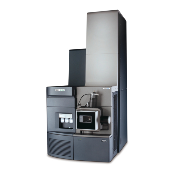
Page 24: Waters Xevo G2-Xs Qtof
(combines ESI and APCI) (see page • NanoLockSpray™ ESI source, (see page 34). The following optional sources are compatible with the Xevo G2-XS QTof: • Combined APPI/APCI source (see page 36, and the Waters APPI Source Operator’s Guide Supplement, part number 71500137602). -
Page 25: Intellistart Technology
An additional reservoir contains solvent for the automated flushing of the solvent delivery system. 1. In Waters documents, the term “fluidics” refers to the IntelliStart Fluidics system, the instrument’s onboard system that delivers sample and solvent to the probe of the mass spectrometer. -
Page 26: Acquity Xevo G2-Xs Qtof Uplc/Ms Systems
The ACQUITY Xevo G2-XS QTof UPLC /MS system includes an ACQUITY UPLC system, and the Waters Xevo G2-XS QTof fitted with either the LockSpray ESI/APCI/ESCi source, or the NanoLockSpray source (with ACQUITY UPLC M-Class only). The ionKey/MS™ system includes an ACQUITY UPLC M-Class system, and the Waters Xevo G2-XS QTof fitted with the ionKey source. - Page 27 Waters Xevo G2-XS QTof Waters ACQUITY Xevo G2-XS QTof UPLC/MS system: Access door to the fluidics valves Sample organizer (optional) Solvent tray Column heater Source interface sliding door Probe High voltage connector for the ESI probe LockSpray source enclosure Xevo G2-XS QTof...
- Page 28 715003588) and Controlling Contamination in UPLC/MS and HPLC/MS Systems (part number 715001307). You can find the latter document on http://www.waters.com; click Services & Support > Support. Waters ACQUITY M-Class Xevo G2-XS QTof UPLC/MS system: Access door to the fluidics valves...
-
Page 29: Software And Data System
Waters Xevo G2-XS QTof Software and data system You can use MassLynx software or UNIFI software to control the mass spectrometer. Both MassLynx software and UNIFI software enable these major operations: • Configuring the system • Creating LC, MS, and MS/MS methods that define operating parameters for a run •... - Page 30 1 Waters Xevo G2-XS QTof Overview UNIFI software UNIFI software integrates mass spectrometry, UPLC chromotography, and informatics data workflows into one system. See UNIFI software user documentation and online Help for more information about using UNIFI software. April 2, 2015, 715004496 Rev. B...
-
Page 31: Lockspray Source And Ionization Modes
You can use the LockSpray source with the ESI, APCI, and ESCi ionization modes (see Chapter 3), and with the ASAP ionization mode (see the Atmospheric Solids Analysis Probe Operator’s Guide Supplement, part number 715002034). Xevo G2-XS QTof fitted with LockSpray source: Solvent tray LockSpray source April 2, 2015, 715004496 Rev. B... -
Page 32: Electrospray Ionization (Esi)
1 Waters Xevo G2-XS QTof Overview Electrospray ionization (ESI) In ESI, a strong electrical charge is applied to the eluent as it emerges from a nebulizer. The droplets that compose the resultant aerosol undergo a reduction in size (solvent evaporation). As solvent continues to evaporate, the charge density increases until the droplet surfaces eject ions (ion evaporation). -
Page 33: Combined Electrospray/Atmospheric Pressure Chemical Ionization (Esci)
LockSpray source and ionization modes the mobile phase react with the reagent ions at atmospheric pressure and typically become protonated (in the positive ion mode) or deprotonated (in the negative ion mode). The sample and reagent ions then pass through the sample cone and into the mass spectrometer. -
Page 34: Nanolockspray Source And Ionization Modes
1 Waters Xevo G2-XS QTof Overview NanoLockSpray source and ionization modes The NanoLockSpray source allows ESI in the flow rate range of 5 to 1,000 nL/min. For a given sample concentration, the ion currents for similar experiments approximate those in normal flow rate electrospray. - Page 35 NanoLockSpray source and ionization modes Xevo G2-XS QTof fitted with NanoLockSpray source: Solvent tray NanoLockSpray source Options shown in the following table are available for the spraying capillary. Spraying capillary options: Option Description Universal NanoFlow™ For flow injection or coupling to ACQUITY nebulizer sprayer UPLC M-Class systems.
-
Page 36: Combined Appi/Apci Source
Atmospheric pressure gas chromotography (APGC) source The Waters APGC couples an Agilent GC with the Xevo G2-XS QTof, making it possible to perform LC and GC analyses in the same system. The APGC provides complementary information to the LC/MS instrument, enabling analysis of compounds of low molecular weight, low-to-intermediate polarity, or both. -
Page 37: Ionkey Source
ionKey source ionKey source The ionKey source performs UPLC separation inside the source of the mass spectrometer. The source precisely positions the iKey™ separation device and integral emitter in the mass spectrometer. All fluid, electronic connections (heater and electrospray high voltage), and gas connections (sheath gas) are made inside the source, eliminating the need to manually connect electronic cables and tubing. -
Page 38: Intellistart Fluidics System
1 Waters Xevo G2-XS QTof Overview IntelliStart Fluidics system The IntelliStart Fluidics system is built into the instrument and controls how the system delivers sample to the source. System connections differ according to whether you use a LockSpray, NanoLockSpray, or ionKey source. See page 223. -
Page 39: Intellistart Fluidics System Physical Layout
IntelliStart Fluidics system IntelliStart Fluidics system physical layout The IntelliStart Fluidics system comprises the components shown in the following figure. IntelliStart Fluidics system components: LockSpray selector valve Access doors Tube guides Optional flow sensor Grounded union Sample selector valve Diverter valve LockSpray pump Sample pump Sample reservoir bottles (A, B, and C) -
Page 40: System Operation
1 Waters Xevo G2-XS QTof Overview The IntelliStart Fluidics system consists of these components: • A sample delivery system composed of a pump, sample selector valve, and a diverter valve used for LC and probe connections. • A LockSpray system, composed of a pump capable of ultra-low flow rates, a LockSpray selector valve, flow sensor, and grounded union. -
Page 41: Ion Optics
Ion optics Ion optics The mass spectrometer’s ion optics operate in the following sequence: Samples from the LC or instrument’s solvent delivery system are introduced at atmospheric pressure into the ionization source. The ions pass through the sample cone and into the vacuum system. The ions pass through the StepWave™... - Page 42 1 Waters Xevo G2-XS QTof Overview Ion optics overview: Reflectron Sample sprayer Tof housing LockSpray sprayer Sample cone StepWave ion guide XS Collision Cell pDRE™ lens Quadrupole Transfer lenses Pusher Detector Isolation valve To vacuum pumps To vacuum pump April 2, 2015, 715004496 Rev. B...
-
Page 43: Leak Sensors
1.5 mL of accumulated leaked liquid in the reservoir that surrounds it. At the same time, the Instrument Console or UNIFI software displays an error message alerting you that a leak has developed. Consult the Waters ACQUITY UPLC Leak Sensor maintenance instructions (part number 71500082506) for complete details. Vacuum system An external roughing pump and three internal turbomolecular pumps maintain the required vacuum. - Page 44 1 Waters Xevo G2-XS QTof Overview April 2, 2015, 715004496 Rev. B...
-
Page 45: Preparing The Mass Spectrometer For Operation
Preparing the Mass Spectrometer for Operation This chapter explains how to start up and shut down the mass spectrometer. Contents: Topic Page Starting the mass spectrometer ............46 Preparing the IntelliStart Fluidics system........49 Rebooting the mass spectrometer ........... 53 Leaving the mass spectrometer ready for operation...... -
Page 46: Starting The Mass Spectrometer
2 Preparing the Mass Spectrometer for Operation Starting the mass spectrometer The Waters Xevo G2-XS QTof is compatible with several types of ACQUITY UPLC systems. See page 26 for details of which ACQUITY UPLC systems are compatible. If you do not use one of these systems, refer to the documentation for your LC system. - Page 47 Starting the mass spectrometer Allow 4 minutes for the PC to initialize. The power and status LEDs change as follows: Tip: • During initialization, the binary solvent manager’s and sample manager’s status LED flashes green. • After the instruments successfully power-on, all power LEDs show steady green.
-
Page 48: Verifying The Instrument's State Of Readiness
2 Preparing the Mass Spectrometer for Operation Verifying the instrument’s state of readiness When the mass spectrometer is in good operating condition, the power and status LEDs show constant green. You can view any error messages in the IntelliStart software (MassLynx), or the UNIFI software. Monitoring the mass spectrometer LEDs LEDs on the mass spectrometer indicate its operational status. -
Page 49: Flow Rates For The Xevo G2-Xs Qtof System
Preparing the IntelliStart Fluidics system Flow rates for the Xevo G2-XS QTof system The Xevo G2-XS QTof system can run at high flow rates. To optimize desolvation, and thus sensitivity, run the system at appropriate gas flows and desolvation temperatures. - Page 50 2 Preparing the Mass Spectrometer for Operation To install the reservoir bottles: To avoid personal contamination with biologically Warning: hazardous, toxic, or corrosive materials, and to avoid spreading contamination to uncontaminated surfaces, wear clean, chemical-resistant, powder-free gloves when working with the reservoir bottles. Remove the reservoir bottle caps.
- Page 51 Preparing the IntelliStart Fluidics system To install the low-volume vials To avoid personal contamination with biologically Warning: hazardous, toxic, or corrosive materials, and to avoid spreading contamination to uncontaminated surfaces, wear clean, chemical-resistant, powder-free gloves when working with the reservoir bottles. If a standard reservoir bottle is fitted, remove it.
-
Page 52: Adjusting The Solvent Delivery Tube Positions
2 Preparing the Mass Spectrometer for Operation Adjusting the solvent delivery tube positions For correct operation of the IntelliStart Fluidics system, you must adjust each solvent delivery tube so that its end is close to, but does not touch, the bottom of the reservoir bottle or low-volume vial. -
Page 53: Purging The Pump
Rebooting the mass spectrometer Purging the pump Each time you replace a solution bottle, you must purge the pump with the solution that you are going to use next. See the mass spectrometer’s online Help for details. Ensure that the end of the tubing is fully submerged in the Requirement: solvent in the wash reservoir. -
Page 54: Leaving The Mass Spectrometer Ready For Operation
2 Preparing the Mass Spectrometer for Operation Leaving the mass spectrometer ready for operation When you are not using the instrument, stop the LC flow, and put the instrument in Source Standby mode, to conserve energy and reduce nitrogen consumption (see the online Help for details). After you return the instrument to Operate mode, the LockSpray source’s Tip: temperature requires up to 30 minutes to stabilize at the relatively high... -
Page 55: Configuring The Lockspray Source
Configuring the LockSpray Source This chapter explains how to configure the LockSpray source for the following ionization modes: • ESI (electrospray ionization) • APCI (atmospheric pressure ionization) • ESCi (combined electrospray and atmospheric pressure ionization) Contents: Topic Page Configuring the LockSpray source ..........56 Configuring for ESI mode .............. -
Page 56: Configuring The Lockspray Source
3 Configuring the LockSpray Source Configuring the LockSpray source The following table summarizes how you configure the LockSpray source for the various ionization modes. Configuring the LockSpray source: Ionization mode Probe type Corona pin fitted? APCI APCI ESCi April 2, 2015, 715004496 Rev. B... -
Page 57: Configuring For Esi Mode
Configuring for ESI mode To operate in ESI mode, you must fit the ESI probe to the LockSpray source enclosure. For more information about using ESI mode, see the Xevo G2-XS QTof system online Help. Installing the ESI probe Required materials •... - Page 58 3 Configuring the LockSpray Source With the probe label facing you, carefully slide the ESI probe into the hole in the probe adjuster assembly, ensuring that the probe location dowel aligns with the location hole in the probe adjuster assembly. Probe label Probe location dowel Location hole of the probe adjuster assembly...
- Page 59 Configuring for ESI mode ESI probe, mounted on the LockSpray source enclosure: Vernier probe adjuster ESI probe Probe locking ring ESI high voltage cable Source window Source enclosure release TP03128 To avoid nitrogen leakage, fully tighten the probe Warning: locking ring. Tighten the probe locking ring to secure the probe in place.
- Page 60 3 Configuring the LockSpray Source Secure the union with a PEEK finger-tight nut and ferrule. Diverter valve Tubing connection ESI probe Probe adjuster assembly To reduce peak broadening, use 0.004-inch ID tubing Recommendation: for sample flow rates ≤1.2 mL/min; use 0.005-inch ID tubing for sample flow rates >1.2 mL/min.
-
Page 61: Removing The Esi Probe
Configuring for ESI mode Removing the ESI probe Required materials Chemical-resistant, powder-free gloves To remove the ESI probe: To avoid personal contamination with biologically Warning: hazardous, toxic, or corrosive materials, and to avoid spreading contamination to uncontaminated surfaces, wear clean, chemical-resistant, powder-free gloves when working with the LC system connections, ESI probe, and source. -
Page 62: Configuring For Apci Mode
Configuring for APCI mode To operate in APCI mode, you must fit the IonSABRE II probe to the LockSpray source enclosure. For more information on using APCI mode, see the Xevo G2-XS QTof system online Help. Installing the IonSABRE II probe Required materials •... - Page 63 Configuring for APCI mode Prepare the instrument for working on the source (see page 99). With the probe label facing you, carefully slide the IonSABRE II probe into the hole in the probe adjuster assembly, ensuring that the probe location dowel aligns with the probe adjuster assembly location hole. Probe label Probe location dowel Probe adjuster assembly...
- Page 64 3 Configuring the LockSpray Source Tighten the probe locking ring to secure the probe in place. An automatic pressure test is performed when the probe is correctly Tip: seated in position. IonSABRE II probe mounted on the source enclosure: IonSABRE II probe Vernier probe adjuster Source window...
-
Page 65: Removing The Ionsabre Ii Probe
Configuring for APCI mode Using tubing ≥ 0.004-inch ID, connect port 2 (the top port) of the diverter valve to the IonSABRE II probe. To reduce peak broadening, use 0.004-inch ID tubing Recommendation: for sample flow rates ≤1.2 mL/min; use 0.005-inch ID tubing for sample flow rates >1.2 mL/min. -
Page 66: Configuring For Esci Mode
ESI and ESCi modes, facilitating data acquisition in ESI and ESCi modes in parallel. For more information on using dual ESI and ESCi modes, see the Xevo G2-XS QTof system online Help. Optimizing the ESI probe for ESCi operation See the mass spectrometer’s online Help for instructions explaining how to... -
Page 67: Configuring The Nanolockspray Source
Configuring the NanoLockSpray Source The NanoLockSpray electrospray ion-source enables the optimized co-introduction of sample and lock-mass compound directly into the ion source. At low flow rates, this feature provides authenticated, exact-mass measurement in both MS and MS/MS modes. Contents: Topic Page Overview of the NanoLockSpray source ......... -
Page 68: Overview Of The Nanolockspray Source
4 Configuring the NanoLockSpray Source Overview of the NanoLockSpray source NanoLockSpray source: LockSpray sprayer inlet NanoLockSpray reference probe Camera Camera focusing ring Z-position adjuster Baffle-motor housing Clear sprayer shield Sprayer safety cover X-position adjuster Thumbscrew (on left-hand side of sprayer platform) Shield Sprayer-platform adjuster assembly holding screw... -
Page 69: Sample Sprayer
Overview of the NanoLockSpray source Schematic of the NanoLockSpray source: LockSpray inlet Sample inlet Baffle Sample cone Spray indexing permits acquisition of sample and LockSpray data in separate data channels, and the baffle design ensures negligible cross-talk between the two sprays. The LockSpray data are used to calculate a correction factor for the mass-scale calibration, which is then applied to the sample data, providing exact-mass information. -
Page 70: Nanoflow Gas Supply
4 Configuring the NanoLockSpray Source NanoFlow gas supply The supply pressure for nebulizer gas flowing to the sample sprayer is electronically controlled, from 0 bar to 2 bar. The optimum pressure is sprayer-dependent, but typically lies between 0.3 bar and 1.0 bar. Purge gas Purge gas typically flows at 350 L/h. -
Page 71: Selecting And Configuring The Nanolockspray Source
The Universal NanoFlow sprayer is installed as standard equipment on the NanoLockSpray source. For installation and maintenance details, see the Waters Universal NanoFlow Sprayer Installation and Maintenance Guide (part number 71500110107). When fitted, the NanoLockSpray source is automatically recognized by the software. -
Page 72: Deploying The Sprayer Platform Adjuster Assembly
4 Configuring the NanoLockSpray Source Deploying the sprayer platform adjuster assembly To move the sprayer platform out of the source: To avoid electrical shock, ensure the safety cover is in place Warning: over the sprayer. Install the sprayer's safety cover, if necessary (see the figure on page 68). -
Page 73: Adjusting The Sprayer Tip Position
Adjusting the sprayer tip position Adjusting the sprayer tip position To adjust the tip position: Using the X-, Y-, and Z-position adjuster controls on the adjuster assembly, move the sample-sprayer tip close to the sampling cone and baffle (see the photo on page 74). -
Page 74: Setting Up The Camera
4 Configuring the NanoLockSpray Source Setting up the camera To set up the camera: Click , to open the Camera Control dialog box. Camera Control view of sprayers and sample cone: Sample cone Baffle Sprayer tip Sample sprayer To focus on the sample sprayer, rotate the camera’s focusing ring (see the figure on page 68). -
Page 75: Optional Glass-Capillary Sprayer
Optional glass-capillary sprayer Optional glass-capillary sprayer The glass-capillary sprayer is designed for use with metal-coated borosilicate glass capillaries. The glass capillaries allow extremely low flow rates (less than 100 nL/min). You only use the glass capillaries for one sample, and then must discard them. - Page 76 4 Configuring the NanoLockSpray Source April 2, 2015, 715004496 Rev. B...
-
Page 77: Installing And Removing The Ionkey Source
Installing and removing the ionKey source The ionKey source performs UPLC separation inside the source of the mass spectrometer. (See “ionKey source” on page 37.) For further information, see the ACQUITY UPLC M-Class System Guide (part number 715003588) and the ionKey/MS System Guide (part number 715004028). -
Page 78: Installing The Ionkey Source
5 Installing and removing the ionKey source Installing the ionKey source The ionKey source enclosure comprises the iKey-separation-device docking port, the iKey-separation-device locking handle, a reference probe, and a microscope camera. In addition, a replacement infill panel and a cable management bracket are provided, to guide the fluid lines for the ionKey source. - Page 79 Installing the ionKey source To avoid personal contamination with biohazards or Warning: toxic materials, and to avoid spreading contamination to uncontaminated surfaces, wear clean, chemical-resistant, powder-free gloves while performing this procedure. The source components can be contaminated. To avoid electric shock, prepare the instrument for work Warning: performed on its source before beginning this procedure.
- Page 80 5 Installing and removing the ionKey source Loosen the two thumbscrews that secure the infill panel to the onboard fluidics panel. Infill panel Thumbscrews Onboard fluidics panel Remove the infill panel from the instrument, and store it in a safe location.
- Page 81 Installing the ionKey source Fit the cable management bracket to the instrument, as follows: Position the cable management bracket so that the vertical cutout is aligned with the upper and lower tabs on the instrument. Partially insert the upper-right section of the bracket into the corresponding slot in the instrument.
- Page 82 5 Installing and removing the ionKey source The thumbscrews must be installed with the screw thread Requirement: uppermost, as shown in the following figure. Infill panel Thumbscrew Onboard fluidics panel 10. Using two hands, fit the ionKey source enclosure to the two supporting studs on the source adaptor housing.
- Page 83 Installing the ionKey source ionKey source connections: Options cable Reference-probe high voltage cable High voltage cable Data/power cable to PSPI connector on µSample manager Fluid inlet line Fluid infusion line Optional post-column addition (PCA) line Fluid waste line 14. Connect the data/power cable to the PSPI connector on the rear of the µSample manager, and use a screwdriver to firmly tighten the connector screws.
- Page 84 5 Installing and removing the ionKey source Source connections to mass spectrometer: Reference-probe high voltage cable Options cable High voltage cable Data/power cable to PSPI connector on µSample manager TP03576 15. Connect the high voltage cable (white) to the high voltage supply outlet on the mass spectrometer.
- Page 85 Installing the ionKey source 18. Identify each fluid line by the part numbers printed on its shrink-wrap tubing. ionKey tubing assemblies: Part Number Description 430003899 Infusion line 430003901 Inlet line 430004126 Waste line 430004476 Optional, post-column addition (PCA) line 19. Guide each fluid line through the fluid-line aperture. Fluid line aperture: Aperture closed Aperture open...
- Page 86 5 Installing and removing the ionKey source µSample manager injection valve: Fluid-inlet line connected to injection valve port 6 20. Connect the fluid-inlet line to port 6 on the injection valve of the µSample manager. 21. Connect the fluid-infusion line to port 2 on the diverter valve of the mass spectrometer.
-
Page 87: Installing Ionkey Source Software
Installing ionKey source software Installing ionKey source software If you are installing an ionKey source on your Xevo G2-XS QTof for the first time, you must install the appropriate MassLynx software SCN and the ACQUITY M-Class driver pack. For details, see the following documents: •... -
Page 88: Removing The Ionkey Source
5 Installing and removing the ionKey source Removing the ionKey source You can remove the ionKey source, and replace it with a conventional interface. If you are using the ionKey source with an ACQUITY UPLC Alternative: M-Class system mounted on an M-Class cart fitted with an ionKey source holder, you can secure the source enclosure to the holder. - Page 89 Removing the ionKey source To remove the ionKey source: Prepare the instrument for working on its source (see page 99). To avoid burn injuries, take great care while working Warning: with the instrument’s source enclosure open; the source can be hot. Remove the iKey separation device from the docking port (see the ionKey/MS System Guide, part number 715004028).
- Page 90 5 Installing and removing the ionKey source April 2, 2015, 715004496 Rev. B...
-
Page 91: Maintenance Procedures
Maintenance Procedures This chapter provides the maintenance guidelines and procedures necessary to maintain the instrument’s performance. Keep to a maintenance schedule, and perform maintenance as required and described in this chapter. Contents: Topic Page Maintenance schedule ..............93 Spare parts ..................95 Troubleshooting with Connections INSIGHT ........ - Page 92 6 Maintenance Procedures Contents: Topic Page Replacing the IonSABRE II probe sample capillary ...... 184 Replacing the LockSpray reference probe capillary....... 191 Replacing the NanoLockSpray reference-probe TaperTip emitter or capillary ..................197 Replacing the ionKey reference-probe capillary......202 Cleaning or replacing the corona pin ..........207 Replacing the IonSABRE II probe heater........
-
Page 93: Maintenance Schedule
Maintenance schedule Maintenance schedule The following table lists periodic maintenance schedules that ensure optimum instrument performance. Maintenance schedule: Procedure Frequency For information... Clean the instrument case. As required. page 111. Empty the nitrogen exhaust Check daily; empty as page 112. trap bottle. - Page 94 6 Maintenance Procedures Maintenance schedule: Procedure Frequency For information... Replace the IonSABRE II When sensitivity page 184. probe capillary. decreases to unacceptable levels or sample flow is inconsistent. Replace the LockSpray probe Annually. page 191. capillary. Replace the NanoLockSpray Annually. page 197.
-
Page 95: Spare Parts
Spare parts Spare parts To ensure that your system operates as designed, use only Waters Quality ® Parts . Visit www.waters.com/wqp for information about Waters Quality Parts, including how to order them. April 2, 2015, 715004496 Rev. B... -
Page 96: Troubleshooting With Connections Insight
Connections INSIGHT is an “intelligent” device management (IDM) Web service that enables Waters to provide proactive service and support for the ACQUITY UPLC system. To use Connections INSIGHT, you must install its service agent software on your workstation. In a client/server system, the service agent must also be installed on the computer from which you control the system. -
Page 97: Safety And Handling
Safety and handling Safety and handling Adhere to the following safety considerations when performing maintenance procedures: To avoid personal contamination with biologically Warning: hazardous, toxic, or corrosive materials, and to avoid spreading contamination to uncontaminated surfaces, wear clean, chemical-resistant, powder-free gloves when working with the LC system connections, ESI probe, and source components. - Page 98 6 Maintenance Procedures To avoid damaging the iKey separation device, observe these Notice: precautions: • Handle the device with care; the component parts are fragile. • Do not subject the device to pressures that exceed 69,000 kPa (690 bar, 10,000 psi). •...
-
Page 99: Preparing The Instrument For Working On The Source
To prepare the instrument for working on the source: Follow one of the actions below, depending on whether you are using MassLynx or UNIFI software to control the Xevo G2-XS QTof: Software Action In the Instrument Console, click Source Standby... -
Page 100: Removing And Refitting The Source Enclosure
6 Maintenance Procedures Removing and refitting the source enclosure Before performing certain maintenance procedures, or fitting the optional dual-mode APPI/APCI, APGC, or ionKey source to the instrument, you must remove the LockSpray or NanoLockSpray source enclosure from the instrument. The following procedures apply to both the standard and optional source Note: enclosures. - Page 101 Removing and refitting the source enclosure Disconnect the probe adjuster and options cables from the instrument’s connectors. To avoid puncture wounds, take great care while Warning: working with the source enclosure open if a corona pin is fitted. The pin’s tip is sharp. To avoid damaging the sample inlet, when removing a Notice: NanoLockSpray source enclosure, you must slide the sprayer...
-
Page 102: Fitting The Source Enclosure To The Instrument
6 Maintenance Procedures Fitting the source enclosure to the instrument Required materials Chemical-resistant, powder-free gloves To fit the source enclosure to the instrument: To avoid personal contamination with biologically Warning: hazardous, toxic, or corrosive materials, and to avoid spreading contamination to uncontaminated surfaces, wear clean, chemical-resistant, powder-free gloves when working with the LC system connections, ESI probe, and source components. -
Page 103: Installing And Removing The Corona Pin
Installing and removing the corona pin Installing and removing the corona pin For APCI, ESCi, and dual-mode APPI/APCI operation, you must fit a corona pin to the source. Installing the corona pin in the source Required materials Chemical-resistant, powder-free gloves To install the corona pin in the source: To avoid personal contamination with biologically Warning:... - Page 104 6 Maintenance Procedures Remove the blanking plug from the corona pin mounting contact. Store the blanking plug in a safe location. Tip: Corona pin mounting contact: Corona-pin mounting-contact blanking plug TP03130 To avoid puncture injury, handle the corona pin with Warning: care.
- Page 105 Installing and removing the corona pin Fit the corona pin to its mounting contact, ensuring that the corona pin is securely mounted and that its tip aligns with the sample-cone orifice. Corona pin: Corona pin Sample-cone orifice TP03130 Close the source enclosure. Look through the source window, and use the vernier probe adjuster (see the figure on page...
-
Page 106: Removing The Corona Pin From The Source
6 Maintenance Procedures Removing the corona pin from the source Required materials Chemical-resistant, powder-free gloves To remove the corona pin from the source: To avoid personal contamination with biologically Warning: hazardous, toxic, or corrosive materials, and to avoid spreading contamination to uncontaminated surfaces, wear clean, chemical-resistant, powder-free gloves when working with the LC system connections, ESI probe, and source components. -
Page 107: Operating The Source Isolation Valve
Operating the source isolation valve Operating the source isolation valve You must close the source isolation valve to isolate the source from the instrument vacuum system for certain maintenance procedures. Required materials Chemical-resistant, powder-free gloves To close the source isolation valve before starting a maintenance procedure: To avoid personal contamination with biologically Warning:... - Page 108 6 Maintenance Procedures Close the source isolation valve by moving its handle counterclockwise, to the vertical position. Isolation valve handle in closed position TP03130 April 2, 2015, 715004496 Rev. B...
- Page 109 Operating the source isolation valve To open the source isolation valve after completing a maintenance procedure: To avoid personal contamination with biologically Warning: hazardous, toxic, or corrosive materials, and to avoid spreading contamination to uncontaminated surfaces, wear clean, chemical-resistant, powder-free gloves when working with the probe and source components.
-
Page 110: Removing O-Rings And Seals
6 Maintenance Procedures Removing O-rings and seals When performing certain maintenance procedures, you must remove O-rings or seals from instrument components. An O-ring removal kit is provided with the instrument. O-ring removal kit: Tool 1 Tool 2 To remove an O-ring: To avoid damaging the component when removing an O-ring or Notice: seal from it, ensure that you do not scratch the component with the... -
Page 111: Cleaning The Instrument Case
Cleaning the instrument case Cleaning the instrument case To avoid abrading the surfaces of the instrument, do not use Notice: abrasives or solvents when cleaning them. Use a soft cloth, dampened with water, to clean the outside surfaces of the mass spectrometer. -
Page 112: Emptying The Nitrogen Exhaust-Trap Bottle
6 Maintenance Procedures Emptying the nitrogen exhaust-trap bottle Inspect the nitrogen exhaust-trap bottle in the instrument exhaust line daily, and empty it before it is more than approximately 10% full. Nitrogen exhaust-trap bottle: To laboratory exhaust port From instrument exhaust connection From instrument pilot valve port... - Page 113 Emptying the nitrogen exhaust-trap bottle To empty the nitrogen exhaust-trap bottle: To stop the LC Flow, follow the action below for your software: Software Action MassLynx In the Instrument Console, click Stop Flow UNIFI On the System Console tool bar, click Stop Flow Pull the source enclosure release (located at the bottom, right-hand side) outward, and swing open the enclosure.
- Page 114 6 Maintenance Procedures To start the LC flow, follow the action below for your software: Software Action MassLynx In the Instrument Console, click Start Flow UNIFI On the System Console tool bar, click Start Flow April 2, 2015, 715004496 Rev. B...
-
Page 115: Maintaining The Roughing Pump
Maintaining the roughing pump Maintaining the roughing pump You can use the mass spectrometer with an Oerlikon Leybold oil-filled roughing pump or an Edwards XDS46i oil-free roughing pump. • For information on connecting the Oerlikon Leybold roughing pump to the mass spectrometer, see page 275. -
Page 116: Gas Ballasting The Oerlikon Leybold Roughing Pump
6 Maintenance Procedures Gas ballasting the Oerlikon Leybold roughing pump To avoid shortening oil life and, consequently, the useful life of Notice: the roughing pump, routinely gas ballast the pump. The roughing pump draws large quantities of solvent vapors that condense in the pump oil, diminishing pumping efficiency. -
Page 117: Inspecting The Roughing Pump Oil Level
Maintaining the Oerlikon Leybold oil-filled roughing pump Inspecting the roughing pump oil level This procedure does not apply to an Edwards oil-free roughing pump. To ensure correct operation of the roughing pump, do not operate it with the oil level below the MIN mark on the sight glass. You must determine the oil level while the roughing pump is Requirement: running. - Page 118 6 Maintenance Procedures Allow the oil to settle in the pump. To avoid personal contamination with Warning: biologically hazardous, toxic, or corrosive materials, and to avoid spreading contamination to uncontaminated surfaces, wear clean, chemical-resistant, powder-free gloves when performing this procedure. To avoid burn injuries, take great care while working Warning: with the roughing pump;...
- Page 119 Maintaining the Oerlikon Leybold oil-filled roughing pump Start the mass spectrometer (see page 46). After you add oil to the pump, the following situations can occur: Tips: • The oil level drops slightly during the first month of operation. • The oil changes color (darkens) over time.
-
Page 120: Replacing The Roughing Pump's Oil And Oil Demister Elements
6 Maintenance Procedures Replacing the roughing pump’s oil and oil demister elements Replace the roughing pump’s oil and oil demister elements annually. This procedure is not required for an Edwards oil-free roughing pump. Note: Required materials • Chemical-resistant, powder-free gloves •... - Page 121 Maintaining the Oerlikon Leybold oil-filled roughing pump To drain the roughing pump’s oil: To avoid personal contamination with biologically Warning: hazardous, toxic, or corrosive materials, and to avoid spreading contamination to uncontaminated surfaces, wear clean, chemical-resistant, powder-free gloves when performing this procedure. To avoid burn injuries, take great care while working with the Warning: roughing pump;...
- Page 122 6 Maintenance Procedures To fill the roughing pump with oil: Using the funnel, pour 1 liter of vacuum oil, type LEYBONOL LVO110, into the oil filler aperture. Use only vacuum oil, type LEYBONOL LVO110. Requirement: After you add the oil, the level appearing in the sight glass can be Tip: above the maximum indication.
- Page 123 Maintaining the Oerlikon Leybold oil-filled roughing pump To remove the roughing pump’s oil demister element: Use the 6-mm Allen wrench to remove the 4 bolts securing the exhaust flange to the roughing pump. Securing bolt Exhaust flange TP02694 Using both hands, carefully remove the exhaust flange and oil demister element from the roughing pump.
- Page 124 6 Maintenance Procedures Use the 10-mm wrench to remove the nut that secures the oil demister element to the exhaust flange. Spring Securing nut TP02686 Holding the oil demister element slightly elevated, to prevent the loss of the spring, remove its flange. TP02692 April 2, 2015, 715004496 Rev.
- Page 125 Maintaining the Oerlikon Leybold oil-filled roughing pump Remove the spring from the oil demister element. To avoid contaminating uncontaminated Warning: surfaces with biologically hazardous, toxic, or corrosive materials, dispose of the oil demister element according to local environmental regulations. Dispose of the oil demister element in accordance with local environmental regulations.
- Page 126 6 Maintenance Procedures Use the 10-mm wrench to fit and tighten the nut that secures the oil demister element to the exhaust flange. TP02686 1 mm exposed thread after tightening Ensure that the inscription “TOP” is at the top of the oil demister element, and, using both hands, carefully fit the oil demister element and exhaust flange to the roughing pump.
-
Page 127: Cleaning The Source Components
Cleaning the source components To prepare for operation after changing the roughing pump’s oil and oil demister element: Connect the power cords for the mass spectrometer and the roughing pump to the main power source. Start the mass spectrometer (see page 46). -
Page 128: Cleaning The Sampling Cone Assembly
6 Maintenance Procedures Cleaning the sampling cone assembly You can remove the sampling cone assembly, which comprises the sample cone, O-ring, and cone gas nozzle, for cleaning without venting the instrument. Removing the sampling cone assembly from the source Required materials Chemical-resistant, powder-free gloves To remove the sampling cone assembly from the source: To avoid personal contamination with biologically... - Page 129 Cleaning the sampling cone assembly Close the source isolation valve (see page 107). Grasp the cone gas nozzle handle, and use it to rotate the sampling cone assembly 90°, moving the handle from the vertical to horizontal position. Sampling cone assembly Cone gas nozzle handle...
-
Page 130: Disassembling The Sampling Cone Assembly
6 Maintenance Procedures Disassembling the sampling cone assembly Required materials • Chemical-resistant, powder-free gloves • Combined 2.5-mm Allen wrench and cone extraction tool To disassemble the sampling cone assembly: To avoid personal contamination with biologically Warning: hazardous, toxic, or corrosive materials, and to avoid spreading contamination to uncontaminated surfaces, wear clean, chemical-resistant, powder-free gloves when handling the sampling cone assembly. - Page 131 Cleaning the sampling cone assembly Slide the collar to the end of the tool. Collar Insert the collar in the sample cone. To avoid damaging the sample cone, which is fragile, do Notice: not place it on its tip; always place it on its flanged base. April 2, 2015, 715004496 Rev.
- Page 132 6 Maintenance Procedures Rotate and lift the tool and collar to remove the sample cone from the cone gas nozzle. Remove the O-ring from the sample cone. Cone gas nozzle Sample cone Cone gas nozzle O-ring handle To avoid contaminating uncontaminated Warning: surfaces with biologically hazardous, toxic, or corrosive materials, dispose of the O-ring according to local...
-
Page 133: Cleaning The Sample Cone And Cone Gas Nozzle
Cleaning the sampling cone assembly Cleaning the sample cone and cone gas nozzle Required materials • Chemical-resistant, powder-free gloves. • Appropriately sized glass vessels in which to completely immerse components when cleaning. Use only glassware not previously cleaned with surfactants. •... - Page 134 6 Maintenance Procedures If the sample cone contains debris, place a drop of formic acid on its orifice. Immerse the sample cone, cone gas nozzle, and cone gas nozzle handle in separate glass vessels containing 1:1 methanol/water. If the components are obviously contaminated, use 45:45:10 Tip: methanol/water/formic acid.
-
Page 135: Assembling The Sampling Cone Assembly
Cleaning the sampling cone assembly Assembling the sampling cone assembly Required materials Chemical-resistant, powder-free gloves To assemble the sampling cone assembly: Notice: • To avoid recontaminating the sampling cone assembly, wear clean chemical-resistant, powder-free gloves during this procedure. • To avoid damaging the sample cone, which is fragile, always place it on its flanged base. -
Page 136: Fitting The Sampling Cone Assembly To The Source
6 Maintenance Procedures Fitting the sampling cone assembly to the source Required materials Chemical-resistant, powder-free gloves To fit the sampling cone assembly to the source: To avoid personal contamination with biologically Warning: hazardous, toxic, or corrosive materials, and to avoid spreading contamination to uncontaminated surfaces, wear clean, chemical-resistant, powder-free gloves when working with the probe and source components. - Page 137 Cleaning the sampling cone assembly Ensure that the source isolation valve is in the closed position (see page 107). Hold the sampling cone assembly so that the cone gas nozzle handle is oriented horizontally and at the top, and then slide the sampling cone assembly into the ion block assembly.
-
Page 138: Cleaning The Ion Block Assembly
6 Maintenance Procedures Cleaning the ion block assembly Clean the ion block assembly if cleaning the sample cone and cone gas nozzle fails to increase signal sensitivity. Removing the ion block assembly from the source assembly Required materials • Chemical-resistant, powder-free gloves •... - Page 139 Cleaning the ion block assembly Remove the source enclosure (see page 100). Removing the source enclosure aids access to the ion block Rationale: assembly. Close the source isolation valve (see page 108). Use the combined 2.5-mm Allen wrench and cone extraction tool to unscrew the 4, captive, ion block assembly securing screws.
- Page 140 6 Maintenance Procedures Remove the ion block assembly from the PEEK ion block support. PEEK ion block support Ion block assembly TP03131 April 2, 2015, 715004496 Rev. B...
-
Page 141: Disassembling The Source Ion Block Assembly
Cleaning the ion block assembly Disassembling the source ion block assembly Required materials • Chemical-resistant, powder-free gloves • Combined 2.5-mm Allen wrench and cone extraction tool • O-ring removal kit To disassemble the ion block assembly: To avoid personal contamination with biologically Warning: hazardous, toxic, or corrosive materials, and to avoid spreading contamination to uncontaminated surfaces, wear... - Page 142 6 Maintenance Procedures Use the combined 2.5-mm Allen wrench and cone extraction tool to loosen the 2 captive screws securing the ion block cover plate. To ensure correct operation of the ion block assembly after Important: reassembly, • do not remove the sampling cone assembly retaining blocks. •...
- Page 143 Cleaning the ion block assembly Grasp the isolation valve, and pull it out of the ion block. Isolation valve O-ring Use the O-ring removal kit to carefully remove the isolation valve O-ring (see page 110). To avoid contaminating uncontaminated Warning: surfaces with biologically hazardous, toxic, or corrosive materials, dispose of the isolation valve O-ring according to local environmental regulations.
- Page 144 6 Maintenance Procedures Use the combined 2.5-mm Allen wrench and cone extraction tool to loosen the captive PEEK terminal block securing screw. Heater cartridge assembly wires PEEK terminal block securing screw To avoid damaging the wires of the heater cartridge Notice: assembly, do not bend or twist them when removing the assembly and ceramic heater mounting block from the ion block.
- Page 145 Cleaning the ion block assembly 10. Carefully remove the PEEK terminal block and ceramic heater mounting block, complete with heater cartridge assembly, from the ion block. You can invert the ion block assembly to facilitate this process. Tip: PEEK terminal block Ceramic heater mounting block April 2, 2015, 715004496 Rev.
- Page 146 6 Maintenance Procedures 11. Use the O-ring removal kit to carefully remove the cover seal from the ion block (see page 110). Cover seal Cone gas O-ring 12. Use the O-ring removal kit to carefully remove the cone gas O-ring from the ion block.
-
Page 147: Cleaning The Ion Block Components
Cleaning the ion block assembly Cleaning the ion block components Required materials • Chemical-resistant, powder-free gloves. • Appropriately sized glass vessels in which to completely immerse components when cleaning. Use only glassware not previously cleaned with surfactants. • HPLC-grade (or better) methanol. •... - Page 148 6 Maintenance Procedures If you used formic acid in the cleaning solution, do as follows: Rinse the components by immersing them separately in glass vessels containing water and then placing the vessels in the ultrasonic bath for 20 minutes. Dry the components by immersing them in separate glass vessels containing methanol and then placing the vessels in the ultrasonic bath for 10 minutes.
-
Page 149: Assembling The Source Ion Block Assembly
Cleaning the ion block assembly Assembling the source ion block assembly Required materials • Chemical-resistant, powder-free gloves • Combined 2.5-mm Allen wrench and cone extraction tool • Isopropyl alcohol in small container • 1:1 methanol/water • Lint-free cloth To assemble the ion block assembly: Notice: •... - Page 150 6 Maintenance Procedures Fit the isolation valve to the ion block assembly, so that it is in the closed position. Fit the ion block cover plate to the ion block assembly, and then use the combined 2.5-mm Allen wrench and cone extraction tool to tighten the 2 captive securing screws for the ion block cover plate.
-
Page 151: Fitting The Ion Block Assembly To The Source Assembly
Cleaning the ion block assembly Fitting the ion block assembly to the source assembly Required materials • Chemical-resistant, powder-free gloves • Combined 2.5-mm Allen wrench and cone extraction tool To fit the ion block assembly to the source assembly: To avoid personal contamination with biologically Warning: hazardous, toxic, or corrosive materials, and to avoid spreading contamination to uncontaminated surfaces, wear... -
Page 152: Cleaning The Stepwave Ion Guide Assembly
6 Maintenance Procedures Cleaning the StepWave ion guide assembly Clean the StepWave ion guide assembly if cleaning the ion block and isolation valve fails to increase signal sensitivity. Handling the StepWave ion guide assembly To avoid damaging the StepWave ion guide assembly, handle it Notice: and its components carefully throughout the cleaning procedure. - Page 153 Cleaning the StepWave ion guide assembly Use the 3-mm Allen wrench to unscrew and remove the 4 screws securing the PEEK ion block support to the adaptor housing. Adaptor housing PEEK ion block support Securing screws StepWave assembly Remove the PEEK ion block support from the adaptor housing. Use the O-ring removal kit to carefully remove all the O-rings from the PEEK ion block support (see page...
-
Page 154: Removing The Stepwave Assembly From The Source Assembly
6 Maintenance Procedures Removing the StepWave assembly from the source assembly Required materials • Chemical-resistant, powder-free gloves • Seal breaker and locator tool • StepWave assembly removal and insertion tool When not in use, store the seal breaker and locator tool on Recommendation: the end of the StepWave assembly removal and insertion tool. - Page 155 Cleaning the StepWave ion guide assembly Seal breaker and locator tool: Handle Seal breaker and locator tool positioned on the adaptor housing: Ion guide cap Adaptor housing Seal breaker and locator tool April 2, 2015, 715004496 Rev. B...
- Page 156 6 Maintenance Procedures Push firmly on the seal breaker and locator tool’s handle, to lever the StepWave assembly slightly out of the adaptor housing. Moving the assembly in this manner releases it from a seal Rationale: located inside the instrument. With the StepWave removal and insertion tool’s cutout uppermost, insert the tool’s pins into the ion block support screw holes above and below the aperture in the pumping block assembly.
- Page 157 Cleaning the StepWave ion guide assembly To avoid damaging the StepWave ion guide assembly, Notice: handle it and its components carefully throughout the cleaning procedure. Remove the StepWave ion guide assembly from the StepWave removal and insertion tool. Using both hands, fit the source enclosure to the two supporting studs on the source adaptor housing.
-
Page 158: Disassembling The Stepwave Ion Guide Assembly
6 Maintenance Procedures Disassembling the StepWave ion guide assembly To avoid personal contamination with biologically Warning: hazardous, toxic, or corrosive materials, and to avoid spreading contamination to uncontaminated surfaces, wear clean, chemical-resistant, powder-free gloves when working with the probe and source components. Required materials •... - Page 159 Cleaning the StepWave ion guide assembly Separate the first and second ion guide assemblies. First ion guide assembly Second ion guide assembly Remove the brown PEEK gasket from the second ion guide assembly. Brown PEEK gasket Second ion guide assembly April 2, 2015, 715004496 Rev.
- Page 160 6 Maintenance Procedures Remove the O-ring from the differential pumping aperture on the second ion guide assembly (see page 110). Differential pumping aperture O-ring Second ion guide assembly To avoid contaminating uncontaminated Warning: surfaces with biologically hazardous, toxic, or corrosive materials, dispose of the O-ring according to local environmental regulations.
-
Page 161: Cleaning The Stepwave Ion Guide Assembly
• HPLC-grade deionized water. • Waters MS Cleaning Solution. • Holding container for used Waters MS Cleaning Solution. • HPLC-grade isopropyl alcohol. • Ultrasonic bath. • Source of oil-free, inert gas (for example, nitrogen) for drying. - Page 162 Hook First ion guide PCB assembly Add Waters MS Cleaning Solution to the glass vessel until the first ion guide PCB assembly is immersed completely. April 2, 2015, 715004496 Rev. B...
- Page 163 Cleaning the StepWave ion guide assembly Repeat step 1 through step 3 for the second ion guide PCB assembly, placing the hook through one of the support rod holes. Hook Second ion guide PCB assembly Place the vessels containing the first ion guide and second ion guide PCB assemblies in the ultrasonic bath for 20 minutes.
- Page 164 6 Maintenance Procedures 12. Carefully pour away and discard the deionized water from both vessels, retaining the ion guide PCB assemblies in each vessel. 13. Fill both vessels with isopropyl alcohol, ensuring that each ion guide PCB assembly is immersed completely. 14.
-
Page 165: Assembling The Stepwave Ion Guide Assembly
Cleaning the StepWave ion guide assembly Assembling the StepWave ion guide assembly Required materials • Chemical-resistant, powder-free gloves • Combined 2.5-mm Allen wrench and cone extraction tool • New O-ring • PEEK gasket • Two StepWave assembly securing screws To assemble the StepWave ion guide assembly: To avoid damaging the StepWave ion guide assembly, handle it Notice: and its components carefully when performing this procedure. - Page 166 6 Maintenance Procedures Fit the brown PEEK gasket to the second ion guide assembly. Ensure that the gasket is orientated correctly. Important: Brown PEEK gasket Second ion guide assembly Align the first ion guide assembly with the second ion guide assembly. Use the combined, 2.5-mm, Allen wrench and cone extraction tool to fit and tighten the 2 screws securing the first ion guide assembly to the second ion guide assembly.
-
Page 167: Fitting The Stepwave Assembly To The Source Assembly
Cleaning the StepWave ion guide assembly Fitting the StepWave assembly to the source assembly Required materials • Chemical-resistant, powder-free gloves • Seal breaker and locator tool • StepWave assembly removal and insertion tool To fit the StepWave assembly to the source assembly: To avoid personal contamination with biologically Warning: hazardous, toxic, or corrosive materials, and to avoid... - Page 168 6 Maintenance Procedures StepWave assembly Cutout Pins StepWave assembly removal and insertion tool With the StepWave removal and insertion tool’s cutout uppermost, insert the StepWave removal and insertion tool’s pins into the ion block support screw holes above and below the aperture in the pumping block assembly.
- Page 169 Cleaning the StepWave ion guide assembly Invert the seal breaker and locator tool, and position it over the end of the StepWave assembly. Inverted seal breaker and locator tool StepWave assembly Adaptor housing Push firmly on the seal breaker and locator tool until the tool’s face contacts the adaptor housing.
-
Page 170: Fitting The Ion Block Support To The Source
6 Maintenance Procedures Fitting the ion block support to the source Required materials • Chemical-resistant, powder-free gloves • 3-mm Allen wrench • New seals and O-rings To fit the PEEK ion block support to the source: To avoid personal contamination with biologically Warning: hazardous, toxic, or corrosive materials, and to avoid spreading contamination to uncontaminated surfaces, wear... -
Page 171: Replacing The Esi Probe Tip And Gasket
Replacing the ESI probe tip and gasket Replacing the ESI probe tip and gasket Replace the ESI probe tip if a blockage occurs in the internal metal sheathing through which the stainless steel capillary passes, or if the probe tip is damaged. - Page 172 6 Maintenance Procedures Remove the ESI probe from the source (see page 61). Use the 10-mm wrench to remove the probe tip. 10-mm wrench Probe tip If the probe tip is difficult to remove, use the 7-mm wrench in Tip: conjunction with the 10-mm wrench.
- Page 173 Replacing the ESI probe tip and gasket Remove the metal gasket from the probe tip. Metal gasket To avoid contaminating uncontaminated Warning: surfaces with biologically hazardous, toxic, or corrosive materials, dispose of the probe tip and metal gasket according to local environmental regulations. Dispose of the metal gasket in accordance with local environmental regulations.
-
Page 174: Fitting The Esi Probe Tip And Gasket
6 Maintenance Procedures Fitting the ESI probe tip and gasket Required materials • Chemical-resistant, powder-free gloves • 10-mm wrench • New metal gasket To fit the ESI probe tip and gasket: To avoid personal contamination with biologically Warning: hazardous, toxic, or corrosive materials, and to avoid spreading contamination to uncontaminated surfaces, wear clean, chemical-resistant, powder-free gloves when working with the probe and source components. -
Page 175: Replacing The Esi Probe Sample Capillary
Replacing the ESI probe sample capillary Replacing the ESI probe sample capillary Replace the stainless steel sample capillary in the ESI probe if it becomes irreversibly blocked, or if it becomes contaminated or damaged. Removing the existing capillary Required materials •... - Page 176 6 Maintenance Procedures Use the combined 2.5-mm Allen wrench and cone extraction tool to remove the 3 probe end cover retaining screws. End cover retaining screws Remove the end cover and gasket from the probe assembly. Nebulizer adjuster knob Gasket End-cover April 2, 2015, 715004496 Rev.
- Page 177 Replacing the ESI probe sample capillary Unscrew and remove the nebulizer adjuster knob. Use the 10-mm wrench to remove the probe tip. 10-mm wrench Probe tip If the probe tip is difficult to remove, use the 7-mm wrench in Tip: conjunction with the 10-mm wrench.
- Page 178 6 Maintenance Procedures Remove the metal gasket from the probe tip. Metal gasket Remove the PEEK union/UNF coupling assembly and capillary from the probe. PEEK union/UNF coupling assembly Capillary Unscrew and remove the knurled collar from the UNF coupling. PEEK union UNF coupling Locknut Knurled collar...
- Page 179 Replacing the ESI probe sample capillary Use the 8-mm wrench, to steady the UNF coupling when loosening Tip: the locknut. 11. Unscrew the finger-tight PEEK union from the UNF coupling. Ferrule PTFE liner sleeve 12. Remove the ferrule and PTFE liner sleeve from the capillary. 13.
-
Page 180: Installing The New Capillary
6 Maintenance Procedures Installing the new capillary Required materials • Chemical-resistant, powder-free gloves • Combined 2.5-mm Allen wrench and cone extraction tool • 10-mm wrench • Needle-nose pliers • LC pump • HPLC-grade (or better) 1:1 acetonitrile/water • Capillary • Ferrule •... - Page 181 Replacing the ESI probe sample capillary To install the new capillary: To avoid personal contamination with biologically Warning: hazardous, toxic, or corrosive materials, and to avoid spreading contamination to uncontaminated surfaces, wear clean, chemical-resistant, powder-free gloves when working with the probe and source components. To avoid puncture wounds, handle the probe with care.
- Page 182 6 Maintenance Procedures Screw the UNF coupling into the PEEK union, finger-tight only. Gently tug on the capillary, testing to ensure that it stays in place. Use the 7-mm wrench to tighten the locknut against the PEEK union until the union can no longer be twisted. Slide a new conductive sleeve and the knurled collar over the capillary.
- Page 183 Replacing the ESI probe sample capillary 15. Carefully push the PEEK union/UNF coupling assembly and capillary into the probe assembly so that the locating pin on the UNF coupling is fully engaged in the locating slot at the head of the probe assembly. UNF coupling locating pin Probe assembly locating slot 16.
-
Page 184: Cleaning The Ionsabre Ii Probe Tip
6 Maintenance Procedures Cleaning the IonSABRE II probe tip Clean the IonSABRE II probe tip when you detect buffer buildup on the probe tip or when the signal intensity weakens. See the mass spectrometer’s online Help for further details. To clean the IonSABRE II probe tip: Stop all liquid flow through the probe, and then start the API gas flow. - Page 185 Replacing the IonSABRE II probe sample capillary To remove the existing capillary: To avoid personal contamination with biologically Warning: hazardous, toxic, or corrosive materials, and to avoid spreading contamination to uncontaminated surfaces, wear clean, chemical-resistant, powder-free gloves when working with the probe and source components. To avoid burn injuries, take great care while performing this Warning: procedure when the probe and source are hot.
- Page 186 6 Maintenance Procedures Remove the end cover and gasket. Nebulizer adjuster knob Gasket End-cover Unscrew and remove the nebulizer adjuster knob. Remove the PEEK union/UNF coupling assembly and capillary from the probe. The PEEK union used with the IonSABRE II probe is notched on Tip: one of its flats, a feature that distinguishes it from the PEEK union used with the ESI probe (see...
-
Page 187: Installing The New Capillary
Replacing the IonSABRE II probe sample capillary Use the 7-mm wrench to loosen the locknut. Unscrew the finger-tight PEEK union from the UNF coupling. Ferrule Remove the ferrule from the capillary. 10. Remove the capillary from the UNF coupling. To avoid contaminating uncontaminated Warning: surfaces with biologically hazardous, toxic, or corrosive materials, dispose of the capillary and ferrule... - Page 188 6 Maintenance Procedures To install the new capillary: To avoid personal contamination with biologically Warning: hazardous, toxic, or corrosive materials, and to avoid spreading contamination to uncontaminated surfaces, wear clean, chemical-resistant, powder-free gloves when working with the probe and source components. Use the sharp knife or PEEK tubing cutter to cut an approximately 60-cm (24-inches) length of red PEEK tubing.
- Page 189 Replacing the IonSABRE II probe sample capillary Requirement: Use a UNF coupling with no grooves, which is appropriate for the IonSABRE II probe. Use the needle-nose pliers to slide a new ferrule onto the capillary. Insert the capillary in the PEEK union, and ensure that it is fully seated.
- Page 190 6 Maintenance Procedures 15. Carefully push the PEEK union/UNF coupling assembly and capillary into the probe assembly so that the locating pin on the UNF coupling is fully engaged in the locating slot at the head of the probe assembly. Probe assembly locating slot UNF coupling locating pin 16.
-
Page 191: Replacing The Lockspray Reference Probe Capillary
Replacing the LockSpray reference probe capillary Replacing the LockSpray reference probe capillary Replace the LockSpray reference probe capillary if it becomes blocked, and you cannot clear it, or if it becomes contaminated or damaged. When replacing the reference probe capillary, you can also replace the microfilter. - Page 192 6 Maintenance Procedures To remove the existing capillary: Prepare the instrument for working on the source (see page 99). To avoid burn injuries, take great care while performing Warning: this procedure when the probe and source are hot. To avoid puncture wounds, if an ESI probe is fitted to Warning: the source, remove the probe before continuing with this procedure.
- Page 193 Replacing the LockSpray reference probe capillary Unscrew the finger-tight nut on the rear of the reference sprayer assembly. Remove the liner tubing and capillary from the reference sprayer assembly. 10. Remove the capillary from the liner tubing. To avoid contaminating uncontaminated Warning: surfaces with biologically hazardous, toxic, or corrosive materials, dispose of the capillary according to local...
-
Page 194: Installing The New Capillary
6 Maintenance Procedures Installing the new capillary Required materials • Chemical-resistant, powder-free gloves • 4-mm wrench • Spares kit for the reference probe assembly • Extender tool for the SealTight nut (included in the spares kit) To install the new capillary: If necessary, unscrew the finger-tight PEEK nut on the outside of the source enclosure, and disconnect the PEEK tubing. - Page 195 Replacing the LockSpray reference probe capillary Loosely tighten the black SealTight nut onto the PEEK union, to hold the liner tube in place. From the other end of the liner tube, carefully push the capillary into the tube until you see it emerge through the PEEK union. Use the finger-tight PEEK nut attached to the PEEK tubing on the outside of the source enclosure, to carefully push the capillary back inside the PEEK union.
- Page 196 6 Maintenance Procedures 10. Carefully thread the capillary through the probe-tip support on the reference-sprayer assembly. Reference-sprayer assembly: Liner tube Finger-tight PEEK nut and ferrule (from LockSpray reference-probe assembly) Probe-tip support Probe tip Probe-tip assembly Capillary 11. Use the finger-tight PEEK nut and ferrule to attach the free end of the liner tube to the rear of the probe-tip support.
-
Page 197: Replacing The Nanolockspray Reference-Probe Tapertip Emitter Or Capillary
Replacing the NanoLockSpray reference-probe TaperTip emitter or capillary Replacing the NanoLockSpray reference-probe TaperTip emitter or capillary Replace the NanoLockSpray reference-probe TaperTip™ emitter or capillary if either is irreversibly blocked, contaminated, or damaged. Removing the NanoLockSpray reference probe Required materials • Chemical-resistant, powder-free gloves •... - Page 198 6 Maintenance Procedures Using the combined, 2.5-mm Allen wrench and cone extraction tool, unscrew the three fixing screws from the top of the NanoLockSpray reference probe. Fixing screw NanoLockSpray reference probe To avoid puncture wounds, handle the probe with care. Warning: The NanoLockSpray reference-probe tip consists of 5 cm of exposed, fused-silica TaperTip emitter, which is sharp and fragile.
-
Page 199: Installing The New Tapertip Emitter And Capillary
Replacing the NanoLockSpray reference-probe TaperTip emitter or capillary Unscrew the capillary PEEK coupler, and remove the capillary from the union. 10. Where appropriate, remove the protective PEEK sleeve from the capillary for reuse. To prevent contaminating the environment with Warning: biologically hazardous or toxic materials, which can be present on the fused silica capillary dispose of the capillary in accordance with local environmental regulations. - Page 200 6 Maintenance Procedures To install the new TaperTip emitter and capillary: If the preset position of the union was not disturbed when you removed the TaperTip emitter and capillary, go to step 2. If the position of the union was disturbed: Using the 1.5-mm Allen wrench, loosen the set screw.
- Page 201 Replacing the NanoLockSpray reference-probe TaperTip emitter or capillary Tighten the PEEK coupler to hold the capillary in place. To avoid puncture wounds, handle the probe with care. Warning: The NanoLockSpray reference-probe tip is an exposed, fused-silica TaperTip emitter which is sharp and fragile. Locate a second PEEK coupler in the bottom end of the union, and slide the TaperTip emitter into the union until it butts against the internal surface of the union.
-
Page 202: Replacing The Ionkey Reference-Probe Capillary
6 Maintenance Procedures Replacing the ionKey reference-probe capillary Replace the ionKey reference-probe TaperTip emitter or capillary if either is irreversibly blocked, contaminated, or damaged. Removing the ionKey reference probe Required materials • Chemical-resistant, powder-free gloves • Combined, 2.5-mm Allen wrench and cone extraction tool •... - Page 203 Replacing the ionKey reference-probe capillary Using the combined, 2.5-mm Allen wrench and cone extraction tool, unscrew the three fixing screws from the top of the ionKey reference probe. Fixing screw ionKey reference probe To avoid puncture wounds, handle the probe with care. Warning: The ionKey reference-probe tip consists of 5 cm of exposed, fused-silica TaperTip emitter, which is sharp and fragile.
-
Page 204: Installing The New Tapertip Emitter And Capillary
6 Maintenance Procedures Unscrew the capillary PEEK coupler, and remove the capillary from the union. 10. Where appropriate, remove the protective PEEK sleeve from the fused silica capillary for reuse. To prevent contaminating the environment with Warning: biologically hazardous or toxic materials, which can be present on the fused silica capillary dispose of the capillary in accordance with local environmental regulations. - Page 205 Replacing the ionKey reference-probe capillary To install the new TaperTip emitter and capillary: If the preset position of the union was not disturbed when you removed the TaperTip emitter and capillary, go to step 2. If the position of the union was disturbed: Using the 1.5-mm Allen wrench, loosen the set screw.
- Page 206 6 Maintenance Procedures Locate the PEEK coupler in the top end of the union, and carefully slide the 75-µm PEEK capillary into the union until it butts against the internal surface of the union. Doing so ensures a minimum dead volume. Rationale: Tighten the PEEK coupler to hold the capillary in place.
-
Page 207: Cleaning Or Replacing The Corona Pin
Cleaning or replacing the corona pin Cleaning or replacing the corona pin Required materials • Chemical-resistant, powder-free gloves • Needle-nose pliers • HPLC-grade (or better) methanol • Lint-free tissue • Lapping film • Corona pin To clean or replace the corona pin: To avoid personal contamination with biologically Warning: hazardous, toxic, or corrosive materials, and to avoid... -
Page 208: Replacing The Ionsabre Ii Probe Heater
6 Maintenance Procedures If you are replacing the corona pin, dispose of the old pin in accordance with local environmental regulations. Install the corona pin in the source (see page 103). Replacing the IonSABRE II probe heater Replace the IonSABRE II probe heater if it fails to heat the probe. Removing the IonSABRE II probe heater Required materials Chemical-resistant, powder-free gloves... - Page 209 Replacing the IonSABRE II probe heater To avoid damaging the probe heater’s electrical Notice: connections, do not twist the heater when removing it from the probe assembly. Gripping the probe heater as shown, carefully pull it off the probe assembly. Probe heater To avoid contaminating uncontaminated Warning:...
-
Page 210: Fitting The New Ionsabre Ii Probe Heater
6 Maintenance Procedures Fitting the new IonSABRE II probe heater Required materials • Chemical-resistant, powder-free gloves • IonSABRE II probe heater To fit the new IonSABRE II probe heater: The probe heater is easily damaged. Take care not to bend, Notice: crush or distort the probe heater’s electrical connections, capillary sleeve, or capillary when fitting the heater over the capillary... -
Page 211: Replacing The Ion Block Source Heater
Replacing the ion block source heater Replacing the ion block source heater Replace the ion block source heater if it fails to heat the ion block when the instrument is pumped-down (evacuated). Required materials • Chemical-resistant, powder-free gloves • Needle-nose pliers •... - Page 212 6 Maintenance Procedures Use the combined 2.5-mm Allen wrench and cone extraction tool to loosen the 2 captive screws securing the ion block cover plate. Ion block cover plate securing screw Ion block cover plate Remove the ion block cover plate. Use the combined 2.5-mm Allen wrench and cone extraction tool to loosen the captive PEEK terminal block securing screw.
- Page 213 Replacing the ion block source heater To avoid damaging the heater cartridge assembly wires, Notice: do not bend or twist them when removing the assembly and ceramic heater mounting block from the ion block. Carefully remove the PEEK terminal block and ceramic heater mounting block, complete with heater cartridge assembly, from the ion block.
- Page 214 6 Maintenance Procedures Use the needle-nose pliers to gently grasp the heat-shrink tubing on the heater cartridge assembly, and slide the assembly out of the ceramic heater mounting block. Heat-shrink tubing Heater cartridge assembly Ceramic heater mounting block 10. Dispose of the heater cartridge assembly. To avoid damaging the wires of the heater cartridge Notice: assembly, do not bend or twist them when fitting the assembly to...
-
Page 215: Replacing The Lockspray Source's Assembly Seals
Replacing the LockSpray source’s assembly seals Replacing the LockSpray source’s assembly seals You do not need to replace the NanoLockSpray source’s assembly seals; Note: this section relates to the LockSpray source only. To avoid excessive leakage of solvent vapor into the laboratory atmosphere, the following seals must be renewed at intervals of no greater than 1 year: •... - Page 216 6 Maintenance Procedures Probe adjuster nebulizer gas seal Probe adjuster assembly probe seal Use the O-ring removal kit to carefully remove the following seals from the source enclosure: • Source enclosure seal • Nebulizer gas seal • Desolvation gas seal April 2, 2015, 715004496 Rev.
-
Page 217: Fitting The New Source Enclosure And Probe Adjuster Assembly Probe Seals
Replacing the LockSpray source’s assembly seals Nebulizer gas seal Desolvation gas seal Source enclosure seal To avoid contaminating uncontaminated Warning: surfaces with biologically hazardous, toxic, or corrosive materials, dispose of the seals according to local environmental regulations. Dispose of all the seals in accordance with local environmental regulations. - Page 218 6 Maintenance Procedures To fit the new source enclosure and probe adjuster assembly probe seals: To avoid personal contamination with biologically Warning: hazardous, toxic, or corrosive materials, and to avoid spreading contamination to uncontaminated surfaces, wear clean, chemical-resistant, powder-free gloves when working with the probe and source components.
-
Page 219: Replacing The Mass Spectrometer's Air Filters
Replacing the mass spectrometer’s air filters Replacing the mass spectrometer’s air filters Replacing the air filter inside the front door Required materials • Needle-nose pliers • New filter To replace the air filter inside the front door: Open the access door to the fluidics pumps (see the figure on page 27). - Page 220 6 Maintenance Procedures Remove the filter cover from the instrument. Filter Filter cover Lift the filter, vertically, from its slot in the instrument. If necessary, use the needle-nose pliers to grasp the filter. Tip: Dispose of the filter. Fit the new filter into the instrument. Fit the filter cover to the instrument.
-
Page 221: Replacing The Air Filters On The Sides Of The Instrument
Replacing the mass spectrometer’s air filters Replacing the air filters on the sides of the instrument Air filters are located on both sides of the instrument. These filters are retained by louvered panels, which you must remove to access the filters. Filter panel on the right-hand side of the instrument: Two similar, smaller panels are located on the left-hand side of the Note:... - Page 222 6 Maintenance Procedures Required materials ® • M4 POZIDRIV screwdriver • New filters To replace the air filters on the sides of the instrument: Use the M4 POZIDRIV screwdriver to remove the screws securing the louvered panel to the instrument enclosure. Remove the louvered panel from the instrument enclosure.
-
Page 223: Replacing The Intellistart Fluidics Tubing
Replacing the IntelliStart Fluidics tubing Replacing the IntelliStart Fluidics tubing In the event of a blockage in the tubing connections between the IntelliStart Fluidics system components, you must replace the tubing. The following procedures explain how to replace the tubing for the LockSpray and sample delivery systems. -
Page 224: Replacing Intellistart Fluidics Tubing (Standard Configuration)
6 Maintenance Procedures Replacing IntelliStart Fluidics tubing (Standard configuration) IntelliStart Fluidics system physical layout: The flow sensor and grounded union are optional fittings if you fit the LockSpray source. They are, however, standard fittings if you fit the NanoLockSpray source. Tubing connections are omitted for clarity. -
Page 225: Removing The Intellistart Fluidics Tubing
Replacing IntelliStart Fluidics tubing (Standard configuration) Removing the IntelliStart Fluidics tubing This procedure explains how to remove the IntelliStart Fluidics tubing, and disconnect the probe tubing at the diverter valve or grounded union. Required materials Chemical-resistant, powder-free gloves To remove the tubing: To avoid personal contamination with biologically Warning: hazardous, toxic, or corrosive materials, and to avoid... -
Page 226: Plumbing The Intellistart Fluidics Lockspray System
6 Maintenance Procedures Plumbing the IntelliStart Fluidics LockSpray system This section explains how to plumb the LockSpray system. Tubing schematic for the LockSpray system: Flow sensor (optional) From external reference From wash bottle bottle (optional) To reference probe Grounded union Tubing (optional) guides... - Page 227 Replacing IntelliStart Fluidics tubing (Standard configuration) Required materials • Chemical-resistant, powder-free gloves. • The Xevo G2-XS QTof Fluidics Tubing and Fitting Kit. This kit contains components for both the sample and LockSpray Tip: system plumbing. • For the LockSpray reference probe connection, –...
- Page 228 6 Maintenance Procedures Open the access doors to the IntelliStart Fluidics system. Using a PEEK nut, Super Flangeless™ ferrule, and stainless steel ring, connect the blue, 1/16-inch, 300-mm, PEEK tubing from the LockSpray pump to port 7 on the LockSpray selector valve, where you use a long finger-tight fitting.
- Page 229 Replacing IntelliStart Fluidics tubing (Standard configuration) Using a long finger-tight fitting, connect orange, 1/16-inch, 680-mm, PEEK tubing from port 1 of the LockSpray selector valve, through tubing guide A, and into reservoir bottle A. ate rs Reservoir bottle A As the tubing emerges from the tubing guide, thread a Requirement: long finger-tight fitting over it.
- Page 230 6 Maintenance Procedures Using a long finger-tight fitting, connect orange, 1/16-inch, 680-mm, PEEK tubing from port 2 of the LockSpray selector valve to the reference reservoir bottle or orange, 1/16-inch, 1,000-mm, PEEK tubing to the external reference bottle. • To use reservoir bottle B as the reference solution, thread the tubing through tubing guide B, and secure it with a long finger-tight fitting.
- Page 231 Replacing IntelliStart Fluidics tubing (Standard configuration) Using a long finger-tight fitting, connect 1/16-inch, 1,000-mm, natural-color PEEK tubing to port 5 of the LockSpray selector valve, and thread the tubing into the waste port. Waste port Wa ters The liquid waste system collects waste without requiring a fitted Tip: connection.
- Page 232 6 Maintenance Procedures 10. Connect the 1/32-in, 6-40 Valco™ compression fitting assembly. Flow sensor Wa ters Long finger-tight PEEK nut and 1/32-inch, PEEK ferrule: 1/32-inch, 6-40 Valco compression fitting assembly: April 2, 2015, 715004496 Rev. B...
- Page 233 Replacing IntelliStart Fluidics tubing (Standard configuration) 11. Using a 1/32-inch, Valco component fitting assembly, connect the red, 1/32-inch, 60-mm, PEEK tubing between the flow sensor and the grounded union, where you use a use a short finger-tight nut and 1/32-inch ferrule. The narrower, 1/32-inch tubing can slip out of the port.
- Page 234 6 Maintenance Procedures To avoid electric shock, do not use stainless steel tubing Warning: to connect the grounded union to the reference probe. 12. Connect the grounded union to the LockSpray source’s reference probe. • For the LockSpray source, use 1/16-inch PEEK tubing connected as follows: –...
-
Page 235: Plumbing The Intellistart Fluidics Sample Delivery System
Replacing IntelliStart Fluidics tubing (Standard configuration) Plumbing the IntelliStart Fluidics sample delivery system This section explains how to plumb the sample delivery system for standard flow applications. For low flow, ACQUITY UPLC M-Class applications, see page 241. IntelliStart sample fluidics delivery tubing schematic: From wash bottle Sample selector valve To probe... - Page 236 6 Maintenance Procedures Required materials • Chemical-resistant, powder-free gloves • The Xevo G2-XS QTof Fluidics Tubing and Fitting Kit This kit contains components for both the sample and LockSpray Tip: system’s plumbing. To plumb the analyte system: To avoid personal contamination with biologically...
- Page 237 Replacing IntelliStart Fluidics tubing (Standard configuration) Slide the PEEK nut, Super Flangeless ferrule, and stainless steel ring over the pump end of the steel tubing. PEEK nut Super Flangeless ferrule Stainless steel tubing Stainless steel ring Insert the tubing in the pump, and tighten the fittings. At the sample selector valve, screw the natural-color PEEK female-to-male adaptor into port 7.
- Page 238 6 Maintenance Procedures Using a long finger-tight fitting, connect 1/16-inch, 1,000-mm, natural-colored PEEK tubing to port 1 of the sample selector valve, and thread the tubing into the waste port. Waste port Wa ters Long finger-tight fitting: The liquid waste system collects waste without requiring a fitted Tip: connection.
- Page 239 Replacing IntelliStart Fluidics tubing (Standard configuration) Using a long finger-tight fitting, connect orange, 1/16-inch, 1,000-mm, PEEK tubing from port 2 of the sample selector valve to the wash bottle. Push the tubing to the bottom of the wash solution, and Requirement: secure so that it cannot float to the surface during use.
- Page 240 6 Maintenance Procedures Using two long finger-tight fittings, connect the red, 1/16-inch, 200-mm, PEEK tubing from port 3 of the sample selector valve to port 3 of the diverter valve. Diverter valve Wa ters Using a long finger-tight fitting, connect 1/16-inch, 1,000-mm, natural-colored PEEK tubing to port 4 of the diverter valve, and thread it securely into the waste port.
-
Page 241: Plumbing The Sample Fluidics Delivery System For Nanolockspray Operation
Plumbing the sample fluidics delivery system for NanoLockSpray operation Connect port 2 of the diverter valve to the source probe, observing the relevant procedure: • For the ESI probe, see page • For the IonSABRE II probe, see page 10. Close the access doors to the IntelliStart Fluidics system. Ensure that the tubing does not become trapped when you Important: close the access doors to the IntelliStart Fluidics system. - Page 242 6 Maintenance Procedures Tubing dimensions (sample delivery system): Length Valve/Port Connection Color (inch) (inch) (mm) Sample/1 Waste reservoir 0.040 1/16 Natural 1,000 Sample/2 Wash reservoir 0.020 1/16 Orange 1,000 Sample/3 Diverter valve 0.005 1/16 Sample/4 Reservoir Bottle A 0.020 1/16 Orange Sample/5 Reservoir Bottle B...
- Page 243 Plumbing the sample fluidics delivery system for NanoLockSpray operation To plumb the analyte system: To avoid personal contamination with biologically Warning: hazardous, toxic, or corrosive materials, and to avoid spreading contamination to uncontaminated surfaces, wear clean, chemical-resistant, powder-free gloves when working with IntelliStart Fluidics tubing and fittings.
- Page 244 6 Maintenance Procedures Slide the PEEK nut, stainless steel ring, and Super Flangeless ferrule over the pump end of the steel tubing. PEEK nut Super Flangeless ferrule Stainless steel tubing Stainless steel ring Insert the tubing in the pump, and tighten the fittings. At the sample selector valve, screw the natural-color PEEK female-to-male adaptor into port 7.
- Page 245 Plumbing the sample fluidics delivery system for NanoLockSpray operation Using a long finger-tight fitting, connect 1/16-inch, 1,000-mm, natural-colored PEEK tubing to port 1 of the sample selector valve, and thread the tubing into the waste port. Waste port Wa ters Long finger-tight fitting: The liquid waste system collects waste without requiring a fitted Tip:...
- Page 246 6 Maintenance Procedures Using a long finger-tight fitting, connect orange 1/16-inch, 680-mm, PEEK tubing from port 4 of the sample selector valve, through tubing guide A, and into reservoir bottle A. Tubing guide A Wa ters Reservoir bottle A As the tubing emerges from the tubing guide, thread the Requirement: long finger-tight fitting over it, push the tubing through the right-hand hole, to the bottom of the reservoir bottle and tighten the fitting.
- Page 247 Plumbing the sample fluidics delivery system for NanoLockSpray operation Using two long finger-tight fittings, connect the red 1/16-inch, 200-mm, PEEK tubing from port 3 of the sample selector valve to port 3 of the diverter valve. Diverter valve Wa ters Using a long finger-tight fitting, connect 1/16 inch, 1000 mm, natural-colored PEEK tubing to port 4 of the diverter valve, and thread it securely into the waste port.
- Page 248 6 Maintenance Procedures Connect port 2 of the diverter valve to the source probe, observing the relevant procedure for the ESI probe (see page 57). 10. Close the access doors to the IntelliStart Fluidics system. Ensure that the tubing does not become trapped when you Important: close the access doors to the IntelliStart Fluidics system.
-
Page 249: Replacing The Fluid Lines Of The Ionkey Source
Replacing the fluid lines of the ionKey source Replacing the fluid lines of the ionKey source If a fluid line becomes damaged, replace it, to ensure optimal performance. Each line is supplied with a pre-fitted PEEK connector assembly at the point where it connects to the ionKey source module. -
Page 250: Removing A Fluid Line
6 Maintenance Procedures You can use these part numbers to identify each line when it is Tip: disconnected from the source. Part numbers are embossed on the shrink-wrap below the ferrule assembly. Removing a fluid line Required materials • Chemical-resistant, powder-free gloves •... - Page 251 Replacing the fluid lines of the ionKey source Fluid-line connector plate location: Connector plate Trace back the fluid line you want to replace, and then disconnect it from the port on the ACQUITY M-Class System, or from the diverter valve on the mass spectrometer. Disconnect the fluid line, as instructed in the supplied Important: documentation.
-
Page 252: Installing A Fluid Line
6 Maintenance Procedures Installing a fluid line Required materials • Chemical-resistant, powder-free gloves • Fluid line assembly To avoid personal contamination with biohazards or Warning: toxic materials, and to avoid spreading contamination to uncontaminated surfaces, wear clean, chemical-resistant, powder-free gloves while performing this procedure. The source components can be contaminated. - Page 253 Replacing the fluid lines of the ionKey source Route the loose (unfitted) end of the fluid line through the fluid-line aperture and out of the source enclosure. You can open and close the aperture by pulling and releasing the Tip: captive aperture assembly as shown below.
-
Page 254: Cleaning The Ionkey Source And Connectors
6 Maintenance Procedures Cleaning the ionKey source and connectors Required materials • Chemical-resistant, powder-free gloves • Lint-free tissue • Water • Isopropanol or methanol • Source of clean, pressurized air To avoid damage, do not use abrasives or solvents to clean the Notice: instrument’s case. - Page 255 Cleaning the ionKey source and connectors To remove buildup from electronic connectors: Open the source door. From the back, gently direct a stream of air from a clean source across the electronic connectors. To prevent contaminating the inside of the source, do not direct air Note: into the source.
- Page 256 6 Maintenance Procedures April 2, 2015, 715004496 Rev. B...
-
Page 257: A Safety Advisories
Warning symbols................258 Notices ....................262 Prohibition symbol ................262 Warnings that apply to all Waters instruments and devices ..263 Warnings that address the replacing of fuses ........ 268 Electrical and handling symbols ............. 270 April 2, 2015, 715004496 Rev. B... -
Page 258: Warning Symbols
The following symbols warn of risks that can arise when you operate or maintain a Waters instrument or device, or a component of an instrument or device. When one of these symbols appear in a manual’s narrative sections or procedures, an accompanying statement identifies the applicable risk and explains how to avoid it. -
Page 259: Specific Warnings
Burst warning This warning applies to Waters instruments and devices fitted with nonmetallic tubing. To avoid injury from bursting, nonmetallic tubing, heed these Warning:... - Page 260 A Safety Advisories Mass spectrometer shock hazard The following warning applies to all Waters mass spectrometers. To avoid electric shock, do not remove the mass spectrometer’s Warning: protective panels. The components they cover are not user-serviceable. The following warning applies to certain mass spectrometers when they are in Operate mode.
- Page 261 Warning symbols Biohazard warning The following warning applies to Waters instruments and devices that can process material containing biohazards, which are substances that contain biological agents capable of producing harmful effects in humans. To avoid infection with potentially infectious, human-sourced...
-
Page 262: Notices
A Safety Advisories Notices Notices appear where an instrument or device can be subject to use or misuse that can damage it or compromise a sample’s integrity. The exclamation point symbol and its associated statement alert you to such risk. To avoid damaging the instrument’s case, do not clean it with Notice: abrasives or solvents. -
Page 263: Warnings That Apply To All Waters Instruments And Devices
Warnings that apply to all Waters instruments and devices Warnings that apply to all Waters instruments and devices When operating this device, follow standard quality-control procedures and the equipment guidelines in this section. Changes or modifications to this unit not expressly approved by the Attention: party responsible for compliance could void the user’s authority to operate the... - Page 264 A Safety Advisories Use caution when working with any polymer tubing under pressure: Warning: • Always wear eye protection when near pressurized polymer tubing. • Extinguish all nearby flames. • Do not use tubing that has been severely stressed or kinked. •...
- Page 265 Warnings that apply to all Waters instruments and devices fare attenzione quando si utilizzano tubi in materiale polimerico Attenzione: sotto pressione: • Indossare sempre occhiali da lavoro protettivi nei pressi di tubi di polimero pressurizzati. • Spegnere tutte le fiamme vive nell'ambiente circostante.
- Page 266 A Safety Advisories 警告:当有压力的情况下使用管线时,小心注意以下几点: • 当接近有压力的聚合物管线时一定要戴防护眼镜。 • 熄灭附近所有的火焰。 • 不要使用已经被压瘪或严重弯曲的管线。 • 不要在非金属管线中使用四氢呋喃或浓硝酸或浓硫酸。 • 要了解使用二氯甲烷及二甲基亚枫会导致非金属管线膨胀,大大降低管线的耐压能力。 경고: 가압 폴리머 튜브로 작업할 경우에는 주의하십시오. • 가압 폴리머 튜브 근처에서는 항상 보호 안경을 착용하십시오. • 근처의 화기를 모두 끄십시오. • 심하게 변형되거나 꼬인 튜브는 사용하지 마십시오. •...
- Page 267 Warnings that apply to all Waters instruments and devices The user shall be made aware that if the equipment is used in a Warning: manner not specified by the manufacturer, the protection provided by the equipment may be impaired. L’utilisateur doit être informé que si le matériel est utilisé d’une Attention: façon non spécifiée par le fabricant, la protection assurée par le matériel risque...
-
Page 268: Warnings That Address The Replacing Of Fuses
A Safety Advisories Warnings that address the replacing of fuses The following warnings pertain to instruments equipped with user-replaceable fuses. If the fuse types and ratings appear on the instrument: To protect against fire, replace fuses with those of the type Warning: and rating printed on panels adjacent to instrument fuse covers. - Page 269 Warnings that address the replacing of fuses If the fuse types and ratings do not appear on the instrument: To protect against fire, replace fuses with those of the type Warning: and rating indicated in the “Replacing fuses” section of the Maintenance Procedures chapter.
-
Page 270: Electrical And Handling Symbols
A Safety Advisories Electrical and handling symbols Electrical symbols The following electrical symbols and their associated statements can appear in instrument manuals and on an instrument’s front or rear panels. Electrical power on Electrical power off Standby Direct current Alternating current Protective conductor terminal Frame, or chassis, terminal Fuse... -
Page 271: Handling Symbols
Electrical and handling symbols Handling symbols The following handling symbols and their associated statements can appear on labels affixed to the packaging in which instruments, devices, and component parts are shipped. Keep upright! Keep dry! Fragile! Use no hooks! April 2, 2015, 715004496 Rev. B... - Page 272 A Safety Advisories April 2, 2015, 715004496 Rev. B...
-
Page 273: B External Connections
The mass spectrometer is heavy. To avoid injury, use Warning: suitable machinery and the supplied harness to lift it. Notice: • Contact Waters Technical Service before moving the instrument. • If you must transport the mass spectrometer, or remove it from service, contact Waters Technical Service for recommended cleaning, flushing, and packaging procedures. -
Page 274: Mass Spectrometer: External Wiring And Vacuum Connections
The instrument’s rear panel connectors are shown below. The two switches above the roughing pump connector are for Requirement: use by Waters service engineers only; they must be kept in the “up” position at all times. Mass spectrometer rear panel connectors:... -
Page 275: Connecting The Oerlikon Leybold Oil-Filled Roughing Pump
Connecting the Oerlikon Leybold oil-filled roughing pump Connecting the Oerlikon Leybold oil-filled roughing pump To connect the alternative oil-free roughing pump, see page 280. Note: Oerlikon Leybold oil-filled roughing pump: Electrical connections Exhaust port Inlet port April 2, 2015, 715004496 Rev. B... - Page 276 B External Connections Required materials • Chemical-resistant, powder-free gloves • 7-mm nut driver • Sharp knife The following items are included in the Xevo G2-XS installation kit: • NW25 center rings • NW25 clamps • 12.7-mm clear PVC exhaust tubing •...
- Page 277 Connecting the Oerlikon Leybold oil-filled roughing pump Install the pump within two degrees of horizontal. To ensure proper ventilation, observe the minimum clearances shown in the following figure. Left side minimum clearance Back side minimum is 150 mm clearance is 150 mm Right side minimum Front side minimum clearance is 150 mm...
- Page 278 (see page 286). 11. Route the open end of the exhaust tubing to a suitable exhaust vent. For further information, see the Waters Xevo G2-XS QTof/Tof Site Preparation Guide (part number 715003608). April 2, 2015, 715004496 Rev. B...
-
Page 279: Making The Electrical Connections To The Oerlikon Leybold Oil-Filled Roughing Pump
13. Make the electrical connections to the roughing pump (see page 279). Making the electrical connections to the Oerlikon Leybold oil-filled roughing pump Roughing pump connections: Xevo G2-XS QTof rear panel Roughing pump main power connector Roughing pump connector Roughing pump d.c. -
Page 280: Connecting The Edwards Oil-Free Roughing Pump
B External Connections Connecting the Edwards oil-free roughing pump The oil-free roughing pump is an alternative to the oil-filled roughing pump. To connect the oil-filled roughing pump, see page 275. Inlet flange Exhaust port flange TP03165 Required materials • Chemical-resistant, powder-free gloves •... - Page 281 Connecting the Edwards oil-free roughing pump To connect the oil-free roughing pump: To avoid personal contamination with Warning: biologically hazardous, toxic, or corrosive materials, and to avoid spreading contamination to uncontaminated surfaces, wear clean, chemical-resistant, powder-free gloves when working with the pump and its connections.
- Page 282 Secure the exhaust tubing with a hose clamp. 10. Route the open end of the exhaust tubing to a suitable exhaust vent. For further information, see the Waters Xevo G2-XS QTof/Tof Site Preparation Guide (part number 715003608). 11. Make the electrical connections to the roughing pump (see page 283).
-
Page 283: Making The Electrical Connections To The Edwards Oil-Free Roughing Pump
Connecting the Edwards oil-free roughing pump Making the electrical connections to the Edwards oil-free roughing pump Roughing pump connections: Roughing pump control connector Xevo G2-XS QTof rear panel TP03165 Roughing pump connector Roughing pump main To power source power connector To make the electrical connections for the oil-free roughing pump: Connect the roughing pump power cord to the main power source. -
Page 284: Connecting To The Nitrogen Gas Supply
B External Connections Connecting to the nitrogen gas supply Required materials • Chemical-resistant, powder-free gloves • 6-mm (¼-in) PTFE tubing (included in the Xevo G2-XS installation kit) • Nitrogen regulator (not supplied) To connect the nitrogen gas supply: Connect one free end of the 6-mm PTFE tubing to the nitrogen inlet port on the rear of the instrument. -
Page 285: Connecting To The Collision Cell Gas Supply
Connecting to the collision cell gas supply The nitrogen must be dry and oil-free, with a purity of at Requirement: least 95%. Connect the free end of the 6-mm PTFE tubing to the nitrogen regulator. Set the nitrogen regulator to 6.5 to 7.0 bar, (94 to 102 psi). Ensure that there are no gas leaks at any of the nitrogen gas supply fittings. -
Page 286: Connecting The Nitrogen Exhaust Line
B External Connections Connecting the nitrogen exhaust line Required materials • Chemical-resistant, powder-free gloves • Sharp knife • Nitrogen exhaust-trap bottle • 4-mm and 12-mm PTFE tubing (included in the Xevo G2-XS installation kit) To connect the nitrogen exhaust line: Warning: •... - Page 287 Connecting the nitrogen exhaust line Nitrogen exhaust-trap bottle: To laboratory exhaust port From instrument exhaust connection From instrument pilot valve port Nitrogen exhaust-trap bottle To avoid gas leaks, use the sharp knife to cut the PTFE Notice: tubing squarely (that is, perpendicular to its horizontal axis). Cut a length of 4-mm tubing long enough to connect the instrument to the nitrogen exhaust-trap bottle.
-
Page 288: Connecting Liquid Waste Lines
B External Connections Connect one end of the tubing to the exhaust port on the instrument’s rear panel. Connect the free end of the tubing to the inlet port on the nitrogen exhaust-trap bottle. To avoid gas leaks, use the sharp knife to cut the PTFE Notice: tubing squarely (that is, perpendicular to its horizontal axis). - Page 289 Connecting liquid waste lines Place a suitable waste container below the mass spectrometer. To avoid distorting the drip tray or causing the drain cup Notice: to leak, restrain the drain cup when attaching or removing the waste line. Slide a drain line over the barbed fitting of the drain (located at the bottom, left-hand side of the mass spectrometer, and on the base of the bottle tray).
- Page 290 B External Connections Positioning of drain tube: Correct Incorrect TP01807 April 2, 2015, 715004496 Rev. B...
-
Page 291: Connecting The Workstation (Systems With No Acquity Lc)
Connecting the workstation (systems with no ACQUITY LC) Connecting the workstation (systems with no ACQUITY LC) Before connecting the workstation to the instrument, set up the workstation according to its accompanying instructions. Locate the workstation within 3 meters (10 feet) of the mass spectrometer. Use shielded network cables with the mass spectrometer to Requirement: ensure compliance with FCC limits. -
Page 292: Connecting Ethernet Cables (Systems With Acquity Lc)
B External Connections Connecting Ethernet cables (systems with ACQUITY LC) Use shielded network cables with the mass spectrometer to Requirement: ensure compliance with FCC limits. To make Ethernet connections: ® Connect one end of one shielded Ethernet cable to the ACQUITY instrument’s network switch, and then connect the free end to the Ethernet card on the preconfigured ACQUITY workstation. - Page 293 Input/output signal connectors Input and output connector locations: Instrument LAN External Connections 1 External connections Service Bus identification tables EPC Com Port EPC Parallel Port External Connections 2 Video Output OUT - External connections 1 External Connections 1 External connections 2 External Connections 2 System Activity Input/output signal connector configuration:...
- Page 294 B External Connections External connections 1: Function Rating Event In 1+, digital signal, +5 V optimum +3.3V max +5V Event In 1-, digital ground, 0V Not used Event In 2+, digital signal, +5 V optimum +3.3V max +5V Event In 2-, digital ground, 0V Not used Not used CE Interlock Out, common...
-
Page 295: Signal Connections
Input/output signal connectors Signal connections Mass spectrometer signal connections: Signal connections Description Analog Out Used for analog-chart-output functionality. The output voltage range is 0 to 2 V. The resolution of the voltage output is 12 bits. Gas Fail Interlock Out Used to stop the solvent flow if the nitrogen gas supply fails. - Page 296 B External Connections To make signal connections: Determine the signal connection location from the silk-screened label on the rear panel of each instrument. Attach the positive and negative leads of the signal cable to the connector. Connector Signal cable TP02585 Slide the clamp (with the bend facing down) into the protective shield.
- Page 297 Input/output signal connectors Insert the connector with the signal cable into the connection cover, position the clamp over the cable leads, and tighten the clamp into place with the second self-tapping screw. Cable leads Clamp Place the second connection cover over the first cover, and snap it into place.
-
Page 298: Connecting The Contact-Closure Cable To An Acquity Lc
B External Connections Connecting the contact-closure cable to an ACQUITY LC The contact-closure cable connects the mass spectrometer’s Gas Fail Interlock signal connectors to the ACQUITY LC system’s Stop Flow In signal connectors. This connection ensures that flow from the ACQUITY LC is stopped if the nitrogen supply to the mass spectrometer’s source is insufficient, or if communication is lost between the ACQUITY LC and the mass spectrometer. - Page 299 Connecting the contact-closure cable to an ACQUITY LC To connect the contact-closure cable: Connect the leads at one end of the contact-closure cable to the Xevo G2-XS’s signal connectors, as shown in the following table. Xevo G2-XS contact-closure cable connections: Connector Function Pin (lead)
-
Page 300: Connecting To The Electricity Source
United States and HAR-type (or better) in Europe. The main power cord must only be replaced with one of adequate rating. For information regarding what cord to use in other countries, contact your local Waters distributor. Connect the female end of the power cord to the receptacle on the rear... -
Page 301: Connecting The Camera For The Nanolockspray Source Or Ionkey Source
Connecting the camera for the NanoLockSpray source or ionKey source Connecting the camera for the NanoLockSpray source or ionKey source The camera for both the NanoLockSpray™ and ionKey™ source is connected to the workstation PC by means of a USB converter. Video output connector Instrument LAN USB converter... - Page 302 B External Connections Select “Include this location in the search”, then: ® • for MassLynx , browse to C:\MassLynx\USBCameraDriver. ® • for UNIFI , browse to C:\Program Files\Waters\UNIFI\USBCameraDriver. Click Next. The software loads. Result: Click Finish. April 2, 2015, 715004496 Rev. B...
-
Page 303: C Materials Of Construction And Compatible Solvents
Solvents used to prepare mobile phases ......... 305 Preventing contamination For information about preventing contamination, refer to Controlling Contamination in Ultra Performance LC/MS and HPLC/MS Systems (part number 715001307), which you can download from the Waters Web site (www.waters.com). April 2, 2015, 715004496 Rev. B... -
Page 304: Items Exposed To Solvent
C Materials of Construction and Compatible Solvents Items exposed to solvent The items that appear in the following table can be exposed to solvent. You must evaluate the safety issues if the solvents used in your application differ from the solvents typically used with these items. See page 305 for details about the most common ingredients used to prepare mobile phases. -
Page 305: Solvents Used To Prepare Mobile Phases
Solvents used to prepare mobile phases Items exposed to solvent: Item Material Insulator PEEK Lamp window Magnesium fluoride Solvents used to prepare mobile phases These solvents are the most common ingredients used to prepare mobile phases for reverse-phase LC/MS (API): •... - Page 306 C Materials of Construction and Compatible Solvents April 2, 2015, 715004496 Rev. B...
Need help?
Do you have a question about the Xevo G2-XS QTof and is the answer not in the manual?
Questions and answers