Sign In
Upload
Manuals
Brands
Waters Manuals
Laboratory Equipment
Xevo G2-XS QTof
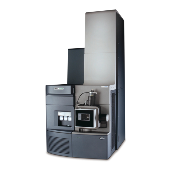
Waters Xevo G2-XS QTof Manuals
Manuals and User Guides for Waters Xevo G2-XS QTof. We have
3
Waters Xevo G2-XS QTof manuals available for free PDF download: Overview And Maintenance Manual, Quick Start Manual
Waters Xevo G2-XS QTof Overview And Maintenance Manual (283 pages)
Brand:
Waters
| Category:
Laboratory Equipment
| Size: 6.94 MB
Table of Contents
General Information
2
Trademarks
2
Customer Comments
3
Contacting Waters
3
Legal Manufacturer
4
Safety Considerations
4
Considerations Specific to the Device
4
Electrical Power Safety Notice
7
Safety Hazard Symbol Notice
7
Equipment Misuse Notice
7
Safety Advisories
7
Operating the Device
8
Applicable Symbols
8
Audience and Purpose
9
Intended Use of the Xevo G2-XS Qtof
9
Quality Control
9
Equipment Misuse Notice
10
EMC Considerations
10
FCC Radiation Emissions Notice
10
ISM Classification: ISM Group 1 Class a
10
EMC Emissions
11
Table of Contents
12
Waters Xevo G2-XS Qtof Overview
20
Waters Xevo G2-XS Qtof
20
Intellistart Technology
20
ACQUITY UPLC/MS Xevo G2-XS Qtof Systems
21
Software and Data System
25
Lockspray Source and Ionization Modes
26
Electrospray Ionization (ESI)
26
Atmospheric Pressure Chemical Ionization (APCI)
27
Combined Electrospray/Atmospheric Pressure Chemical Ionization (Esci)
27
Atmospheric Solids Analysis Probe (ASAP)
28
Nanolockspray Source and Ionization Modes
28
Combined APPI/APCI Source
29
Atmospheric Pressure Gas Chromatography (APGC)
30
Ionkey Source
30
Unispray Lockspray Source
30
Intellistart Fluidics System
31
Fluidics System Overview
31
Intellistart Fluidics System Physical Layout
31
System Operation
33
Ion Optics
33
Leak Sensors
35
Vacuum System
35
Preparing the Mass Spectrometer for Operation
36
Starting the Mass Spectrometer
36
Verifying the Instrument's State of Readiness
38
Monitoring the Mass Spectrometer Leds
38
Calibration
38
Flow Rates for the Xevo G2-XS Qtof System
38
Preparing the Fluidics System
39
Installing the Reservoir Bottles
39
Installing the Low-Volume Vials
40
Adjusting the Solvent Delivery Tube Positions
41
Purging the Pump
42
Rebooting the Mass Spectrometer
42
Leaving the Mass Spectrometer Ready for Operation
43
Emergency Shutdown
43
Configuring the Lockspray Source
44
Configuring the Lockspray II Source
44
Configuring for ESI Mode
44
Installing the ESI Probe
44
Removing the ESI Probe
48
Configuring for APCI Mode
48
Installing the Ionsabre II Probe
49
Removing the Ionsabre II Probe
51
Configuring for Esci Mode
51
Optimizing the ESI Probe for Esci Operation
52
Configuring the Nanolockspray Source
53
Overview of the Nanolockspray Source
53
Sample Sprayer
55
Lockspray Sprayer
55
Nanoflow Gas Supply
55
Purge Gas
55
Sprayer Platform Adjuster Assembly
55
Selecting and Configuring the Nanolockspray Source
56
Deploying the Sprayer Platform Adjuster Assembly
56
Moving the Sprayer Platform out of the Source
56
Moving the Sprayer Platform into the Source
57
Adjusting the Sprayer Tip Position
57
Setting up the Camera
57
Optional Glass Capillary Sprayer
59
Plumbing the Fluidics Sample Delivery System for Nanolockspray Operation
59
Installing and Removing the Ionkey Source
66
Ionkey Source
66
Installing the Ionkey Source
66
Installing the Ionkey Source
68
Installing Ionkey Source Software
75
Installing the Camera in the Ionkey Source
76
Removing an Ionkey Source
76
Flow Rates for the Xevo G2-XS Qtof System
78
Unispray Lockspray Source
79
Installing the Unispray Source
81
Installing the Unispray Lockspray Source
81
Removing the Unispray Source
84
Removing the Unispray Lockspray Source
84
Maintenance Procedures
86
Maintenance Schedule
86
Spare Parts
88
Safety and Handling
88
Preparing the Instrument for Working on the Source
89
Using Masslynx Software to Prepare the Instrument for Operations on or Inside Its Source
90
Using UNIFI Software to Prepare the Instrument for Working on the Source
90
Removing and Refitting the Source Enclosure
90
Removing the Source Enclosure from the Instrument
91
Fitting the Source Enclosure to the Instrument
92
Installing and Removing the Corona Pin
93
Installing the Corona Pin in the Source
93
Removing the Corona Pin from the Source
95
Operating the Source Isolation Valve
96
Closing the Source Isolation Valve
97
Opening the Source Isolation Valve
98
Removing O-Rings and Seals
99
O-Ring Removal Kit
99
Cleaning the Instrument Case
100
Emptying the Nitrogen Exhaust Trap Bottle
100
Maintaining the Roughing Pump
102
Maintaining the Oil-Filled Roughing Pump
103
Gas Ballasting the Oil-Filled Roughing Pump
104
Inspecting the Roughing Pump Oil Level
105
Adding Oil to the Roughing Pump
105
Replacing the Roughing Pump's Oil and Oil Demister Elements
107
Cleaning the Source Components
113
Cleaning the Sampling Cone Assembly
113
Removing the Sampling Cone Assembly from the Source
114
Disassembling the Sampling Cone Assembly
115
Cleaning the Sample Cone and Cone Gas Nozzle
118
Assembling the Sampling Cone Assembly
119
Fitting the Sampling Cone Assembly to the Source
120
Cleaning the Ion Block Assembly
121
Removing the Ion Block Assembly from the Source Assembly
122
Disassembling the Source Ion Block Assembly
123
Cleaning the Ion Block Components
128
Assembling the Source Ion Block Assembly
129
Fitting the Ion Block Assembly to the Source Assembly
130
Cleaning the Stepwave Ion Guide Assembly
131
Handling the Stepwave Ion Guide Assembly
131
Removing the Ion Block Support from the Source Assembly
131
Removing the Stepwave Assembly from the Source Assembly
133
Disassembling the Stepwave Ion Guide Assembly
137
Cleaning the Stepwave Ion Guide Assembly
139
Assembling the Stepwave Ion Guide Assembly
142
Fitting the Stepwave Assembly to the Source Assembly
143
Fitting the Ion Block Support to the Source
145
Maintaining the ESI Probe
146
Replacing the ESI Probe Tip and Gasket
146
Replacing the ESI Probe Capillary
149
Cleaning the Ionsabre II Probe Tip
167
Replacing the Ionsabre II Probe Sample Capillary
167
Removing the Existing Capillary
167
Installing the New Capillary
170
Replacing the Lockspray Reference Probe Capillary
172
Removing the Existing Capillary
173
Installing the New Capillary
175
Replacing the Lockspray II Reference Probe
178
Removing the Existing One-Piece Reference Probe
180
Installing the New Reference Probe
184
Replacing the Nanolockspray Reference Probe Tapertip Emitter or Capillary
188
Removing the Nanolockspray Reference Probe
188
Installing the New Tapertip Emitter and Capillary
190
Replacing the Ionkey Reference-Probe Capillary
192
Removing the Ionkey Reference-Probe Capillary
192
Cleaning or Replacing the Corona Pin
197
Maintaining the Unispray Impactor Pin
198
Cleaning or Replacing the Unispray Impactor Pin
199
Removing and Installing the Unispray Impactor Pin
199
Replacing the Unispray Probe Assembly
200
Removing the Unispray Probe Assembly
200
Installing the Unispray Probe Assembly
201
Replacing the Ionsabre II Probe Heater
203
Removing the Ionsabre II Probe Heater
203
Fitting the New Ionsabre II Probe Heater
205
Replacing the Ion Block Source Heater
206
Replacing the Source Assembly Seals
209
Removing the Probe Adjuster Assembly Probe and Source Enclosure Seals
210
Fitting the New Source Enclosure and Probe Adjuster Assembly Probe Seals
212
Replacing the Mass Spectrometer's Air Filters
213
Replacing the Air Filter Inside the Front Door
213
Replacing the Air Filters on the Sides of the Instrument
215
Replacing the Intellistart Fluidics Tubing
217
Replacing Intellistart Fluidics Tubing (Standard Configuration)
217
Intellistart Fluidics System Physical Layout
217
Removing the Intellistart Fluidics Tubing
219
Plumbing the Intellistart Fluidics Lockspray System
220
Plumbing the Intellistart Fluidics Sample Delivery System
227
Plumbing the Fluidics Sample Delivery System for Nanolockspray Operation
233
Replacing the Fluidic Lines of the Ionkey Source
239
Removing a Fluid Line
240
Installing a Fluid Line
241
Cleaning the Ionkey Source and Connectors
242
A Safety Advisories
245
Warning Symbols
245
Specific Warnings
246
Notices
247
Bottles Prohibited Symbol
248
Required Protection
248
Warnings that Apply to All Waters Instruments and Devices
248
Warnings that Address the Replacement of Fuses
252
Electrical Symbols
254
Handling Symbols
255
B External Connections
256
Mass Spectrometer External Wiring and Vacuum Connections
256
Connecting the Oil-Filled Roughing Pump
258
Making the Electrical Connections to the Oil-Filled Roughing Pump
262
Connecting the Edwards Oil-Free Roughing Pump
263
Making the Electrical Connections to the Edwards Oil-Free Roughing Pump
266
Connecting to the Nitrogen Gas Supply
267
Connecting to the Collision Cell Gas Supply
268
Connecting the Nitrogen Exhaust Line
269
Connecting Liquid Waste Lines
271
Connecting the Workstation (Systems with no ACQUITY LC)
272
Connecting to the Workstation
273
Connecting the Workstation to the Power Source
273
Connecting Ethernet Cables (Systems with ACQUITY LC)
273
Input/Output Signal Connectors
274
Signal Connections
276
Connecting the Contact-Closure Cable to an ACQUITY LC
278
Connecting to the Electricity Source
280
Connecting the Camera for the Nanolockspray Source or Ionkey Source
280
Installing the Camera Driver Software
281
C Materials of Construction and Compatible Solvents
282
Preventing Contamination
282
Items Exposed to Solvent
282
Solvents Used to Prepare Mobile Phases
283
Advertisement
Waters Xevo G2-XS QTof Overview And Maintenance Manual (306 pages)
Brand:
Waters
| Category:
Laboratory Equipment
| Size: 5.12 MB
Table of Contents
Copyright Notice
3
Trademarks
3
Customer Comments
4
Contacting Waters
4
Safety Considerations
5
Safety Hazard Symbol Notice
5
Electrical Power Safety Notice
9
Safety Advisories
9
Operating the Xevo G2-XS Qtof
10
Applicable Symbols
10
Audience and Purpose
11
Calibrating
11
Quality Control
12
Equipment Misuse Notice
12
EMC Considerations
13
Canada Spectrum Management Emissions Notice
13
ISM Classification: ISM Group 1 Class a
13
EC Authorized Representative
14
Table of Contents
15
1 Waters Xevo G2-XS Qtof Overview
23
Waters Xevo G2-XS Qtof
24
Intellistart Technology
25
ACQUITY Xevo G2-XS Qtof UPLC/MS Systems
26
Software and Data System
29
Lockspray Source and Ionization Modes
31
Electrospray Ionization (ESI)
32
Atmospheric Pressure Chemical Ionization (APCI)
32
Combined Electrospray/Atmospheric Pressure Chemical Ionization (Esci)
33
Atmospheric Solids Analysis Probe (ASAP)
33
Nanolockspray Source and Ionization Modes
34
Combined APPI/APCI Source
36
Atmospheric Pressure Gas Chromotography (APGC) Source
36
Ionkey Source
37
Intellistart Fluidics System
38
Intellistart Fluidics System Physical Layout
39
System Operation
40
Ion Optics
41
Leak Sensors
43
Vacuum System
43
2 Preparing the Mass Spectrometer for Operation
45
Starting the Mass Spectrometer
46
Verifying the Instrument's State of Readiness
48
Monitoring the Mass Spectrometer Leds
48
Calibration
48
Flow Rates for the Xevo G2-XS Qtof System
49
Preparing the Intellistart Fluidics System
49
Installing the Reservoir Bottles
49
Adjusting the Solvent Delivery Tube Positions
52
Purging the Pump
53
Rebooting the Mass Spectrometer
53
Leaving the Mass Spectrometer Ready for Operation
54
Emergency Shutdown of the Mass Spectrometer
54
3 Configuring the Lockspray Source
55
Configuring the Lockspray Source
56
Configuring for ESI Mode
57
Installing the ESI Probe
57
Removing the ESI Probe
61
Configuring for APCI Mode
62
Installing the Ionsabre II Probe
62
Removing the Ionsabre II Probe
65
Configuring for Esci Mode
66
Optimizing the ESI Probe for Esci Operation
66
4 Configuring the Nanolockspray Source
67
Overview of the Nanolockspray Source
68
Sample Sprayer
69
Lockspray Sprayer
69
Nanoflow Gas Supply
70
Purge Gas
70
Sprayer Platform Adjuster Assembly
70
Selecting and Configuring the Nanolockspray Source
71
Deploying the Sprayer Platform Adjuster Assembly
72
Adjusting the Sprayer Tip Position
73
Setting up the Camera
74
Optional Glass-Capillary Sprayer
75
5 Installing and Removing the Ionkey Source
77
Installing the Ionkey Source
78
Installing Ionkey Source Software
87
Installing the Camera in the Ionkey Source
87
Removing the Ionkey Source
88
6 Maintenance Procedures
91
Maintenance Schedule
93
Spare Parts
95
Troubleshooting with Connections INSIGHT
96
Safety and Handling
97
Preparing the Instrument for Working on the Source
99
Removing and Refitting the Source Enclosure
100
Removing the Source Enclosure from the Instrument
100
Fitting the Source Enclosure to the Instrument
102
Installing and Removing the Corona Pin
103
Installing the Corona Pin in the Source
103
Removing the Corona Pin from the Source
106
Operating the Source Isolation Valve
107
Removing O-Rings and Seals
110
Cleaning the Instrument Case
111
Emptying the Nitrogen Exhaust-Trap Bottle
112
Maintaining the Roughing Pump
115
Maintaining the Oerlikon Leybold Oil-Filled Roughing Pump
115
Gas Ballasting the Oerlikon Leybold Roughing Pump
116
Inspecting the Roughing Pump Oil Level
117
Adding Oil to the Roughing Pump
117
Replacing the Roughing Pump's Oil and Oil Demister Elements
120
Cleaning the Source Components
127
Cleaning the Sampling Cone Assembly
128
Removing the Sampling Cone Assembly from the Source
128
Disassembling the Sampling Cone Assembly
130
Cleaning the Sample Cone and Cone Gas Nozzle
133
Assembling the Sampling Cone Assembly
135
Fitting the Sampling Cone Assembly to the Source
136
Cleaning the Ion Block Assembly
138
Removing the Ion Block Assembly from the Source Assembly
138
Disassembling the Source Ion Block Assembly
141
Cleaning the Ion Block Components
147
Assembling the Source Ion Block Assembly
149
Fitting the Ion Block Assembly to the Source Assembly
151
Cleaning the Stepwave Ion Guide Assembly
152
Handling the Stepwave Ion Guide Assembly
152
Removing the Ion Block Support from the Source Assembly
152
Removing the Stepwave Assembly from the Source Assembly
154
Disassembling the Stepwave Ion Guide Assembly
158
Cleaning the Stepwave Ion Guide Assembly
161
Assembling the Stepwave Ion Guide Assembly
165
Fitting the Stepwave Assembly to the Source Assembly
167
Fitting the Ion Block Support to the Source
170
Replacing the ESI Probe Tip and Gasket
171
Removing the ESI Probe Tip and Gasket
171
Fitting the ESI Probe Tip and Gasket
174
Replacing the ESI Probe Sample Capillary
175
Removing the Existing Capillary
175
Installing the New Capillary
180
Cleaning the Ionsabre II Probe Tip
184
Replacing the Ionsabre II Probe Sample Capillary
184
Removing the Existing Capillary
184
Installing the New Capillary
187
Replacing the Lockspray Reference Probe Capillary
191
Removing the Existing Capillary
191
Installing the New Capillary
194
Replacing the Nanolockspray Reference-Probe Tapertip Emitter or Capillary
197
Removing the Nanolockspray Reference Probe
197
Installing the New Tapertip Emitter and Capillary
199
Replacing the Ionkey Reference-Probe Capillary
202
Removing the Ionkey Reference Probe
202
Installing the New Tapertip Emitter and Capillary
204
Cleaning or Replacing the Corona Pin
207
Replacing the Ionsabre II Probe Heater
208
Removing the Ionsabre II Probe Heater
208
Fitting the New Ionsabre II Probe Heater
210
Replacing the Ion Block Source Heater
211
Replacing the Lockspray Source's Assembly Seals
215
Removing the Probe Adjuster Assembly Probe and Source Enclosure Seals
215
Fitting the New Source Enclosure and Probe Adjuster Assembly Probe Seals
217
Replacing the Mass Spectrometer's Air Filters
219
Replacing the Air Filter Inside the Front Door
219
Replacing the Air Filters on the Sides of the Instrument
221
Replacing the Intellistart Fluidics Tubing
223
Replacing Intellistart Fluidics Tubing (Standard Configuration)
224
Removing the Intellistart Fluidics Tubing
225
Plumbing the Intellistart Fluidics Lockspray System
226
Plumbing the Intellistart Fluidics Sample Delivery System
235
Plumbing the Sample Fluidics Delivery System for Nanolockspray Operation
241
Replacing the Fluid Lines of the Ionkey Source
249
Removing a Fluid Line
250
Installing a Fluid Line
252
Cleaning the Ionkey Source and Connectors
254
A Safety Advisories
257
Warning Symbols
258
Specific Warnings
259
Notices
262
Prohibition Symbol
262
Warnings that Apply to All Waters Instruments and Devices
263
Warnings that Address the Replacing of Fuses
268
Electrical and Handling Symbols
270
Electrical Symbols
270
Handling Symbols
271
B External Connections
273
Mass Spectrometer: External Wiring and Vacuum Connections
274
Connecting the Oerlikon Leybold Oil-Filled Roughing Pump
275
Making the Electrical Connections to the Oerlikon Leybold Oil-Filled Roughing Pump
279
Connecting the Edwards Oil-Free Roughing Pump
280
Making the Electrical Connections to the Edwards Oil-Free Roughing Pump
283
Connecting to the Nitrogen Gas Supply
284
Connecting to the Collision Cell Gas Supply
285
Connecting the Nitrogen Exhaust Line
286
Connecting Liquid Waste Lines
288
Connecting the Workstation (Systems with no ACQUITY LC)
291
Connecting Ethernet Cables (Systems with ACQUITY LC)
292
Input/Output Signal Connectors
292
Signal Connections
295
Connecting the Contact-Closure Cable to an ACQUITY LC
298
Connecting to the Electricity Source
300
Connecting the Camera for the Nanolockspray Source or Ionkey Source
301
Installing the Camera Driver Software
301
C Materials of Construction and Compatible Solvents
303
Preventing Contamination
303
Items Exposed to Solvent
304
Solvents Used to Prepare Mobile Phases
305
Waters Xevo G2-XS QTof Quick Start Manual (2 pages)
No flow from fluidics
Brand:
Waters
| Category:
Laboratory Equipment
| Size: 0.04 MB
Table of Contents
Symptoms
1
Environment
1
Cause
2
FIX or WORKAROUND
2
Additional Information
2
Advertisement
Advertisement
Related Products
Waters Xevo G2 QTof
Waters GCT Premier
Waters 2707
Waters 717plus
Waters Categories
Laboratory Equipment
Security Sensors
Control Unit
Measuring Instruments
Water Pump
More Waters Manuals
Login
Sign In
OR
Sign in with Facebook
Sign in with Google
Upload manual
Upload from disk
Upload from URL