Table of Contents
Advertisement
Advertisement
Table of Contents
Troubleshooting

Related Manuals for Ciena LE-427


Summary of Contents for Ciena LE-427
- Page 2 Ciena Corporation will not be liable for any damages of any kind arising from the use of this User Guide, including but not limited to direct, indirect, incidental punitive, and consequential damages.
- Page 3 Ciena Corporation and is protected by U.S. and international copyright laws. All software mentioned in this User Guide is the property Ciena Corporation or its software suppliers and protected by U.S. and international copyright laws. The content in this User Guide may be used as a resource.
- Page 4 Those that are registered with the United States Patent and Trademark Office (USPTO). Those that are being used, but have not yet completed the registration process. Both categories are protected, although those that are registered provide visible notice of the corporation’s rights and stronger enforcement provisions.
- Page 5 ISO Compliance LE-3xx/LE-4xx Hardware Installation & User Guide...
-
Page 6: Important Safety Information
Important Safety Information This equipment is to be installed and maintained by qualified service WARNING: personnel only. WARNUNG: Dieses Gerät darf nur von qualifiziertem Wartungspersonal installiert und gewartet werden. AVERTISSEMENT: Cet équipement doit être installé et entretenu uniquement par un personnel de service qualifié. Installation och underhåll av utrustningen får endast ske av utbildad VARNING: servicepersonal. -
Page 7: Table Of Contents
LE-427......... - Page 8 Removable Power Supplies ........24 Power Cord and Power Cord Restraints ......25 Power Supply LED .
- Page 9 E-mail Address ......... .81 Telephone and Fax.
- Page 10 LE-3xx/LE-4xx Hardware Installation & User Guide...
-
Page 11: About This Guide
Introduction to this Guide This User Guide is designed to help network technicians and system administrators install and manage the LightningEdge 3xx Service Delivery Switch, the LightningEdge 3xx Service Concentration Switch, and the LightningEdge 4xx Service Concentration Switch from Ciena Corporation. Intended Audience This publication is intended for users, such as network technicians and system administrators, who will install these devices into a services distribution infrastructure. - Page 12 Symbols denote text that requires special attention. The information contained alongside a symbol corresponds to one of three levels: WARNING: This symbol is used to highlight information so the user can avoid personal injury. This symbol is used to highlight information so the user can avoid CAUTION: equipment damage or data loss.
-
Page 13: Chapter 1: Overview
Model Numbers and Product Numbers may overlap. For example, Model Number “LEAC-0311VB” and Product Number “LE-311v” are the same. The Ciena/World Wide Packets Service Concentration Switch (SCS) and Service Delivery Switch (SDS) family of products provide Ethernet connectivity to buildings and residences for the purpose of delivering high-speed voice, video, and data connectivity. -
Page 14: Interconnectivity
NTERCONNECTIVITY The LE-4xx SCS is designed to work in concert with the other members of the Ciena/World Wide Packets family of products to deliver complete, integrated service offerings from a single provider or multiple providers. LE-4xx SCS devices are specifically designed to aggregate subscribers, either directly connected using an SDS or an aggregation device such as another device. - Page 15 Abonnentporter på alle LE-3xx SCS/SDS- og LE-4xx SCS-enhetene er beregnet på sammenkobling bare innenfor leverandørens nettverk. Koblingen til flere leverandørers nettverk (eller PSTN - det offentlige svitsjede telefoninettet) kan gjøres med andre løsninger som er tilgjengelige fra Ciena/World Wide Packets produktfamilie. ATTENZIONE:...
-
Page 16: Snmp
• Device Manager The LE-4xx SCS is managed directly using the Ciena/World Wide Packets Ethernet Services Manager (ESM). The LE-4xx SCS can also be managed using any SNMP manager. Services can be provisioned in real time without requiring software reloads or network outages. Alarms are also managed using NMS. -
Page 17: Radius
NTERCONNECTIVITY RADIUS Remote Authentication Dial-In User Service (RADIUS) protocol that authenticates dial-in users and authorizes their access to the requested device or service. This type of authentication provides added security, ensuring that only the authenticated administrator can access the LE- 4xx SCS for management configuration. -
Page 18: Igmp
Power and Redundancy The LE-310 is only available as an AC-powered device. The LE-311, LE-311v, LE-327, and LE-427 feature hot-swappable power supplies. One power supply is required for normal operation while a second power supply can be added for redundancy. These removable power supplies can be ordered as either AC or DC devices. -
Page 19: Hardware Description
ARDWARE ESCRIPTION Hardware Description The following LE-3xx SCS/SDS models are currently available: Table 1-1: The 3xx SCS/SDS Family of Products Model Interfaces Location of Rack Units Power Connectors LE-310 • 8 10/100BASE-TX Ethernet ports on front, • 3 100/1000 SFP power connections on rear •... -
Page 20: Le-310
1 10/100BASE-TX power connections on rear of device The LE-427 chassis occupies only one rack unit (RU) of a standard 19-inch equipment rack, allowing up to 42 devices to share a single rack (without redundant power supplies). LE-310 On the LE-310, the Status LEDs for the 10/100/1000Base-TX ports are located in a bank to the right of the actual ports. -
Page 21: Le-327
ARDWARE ESCRIPTION On the LE-311 and LE-311v, the Status LEDs for the 10/100 Mbps ports are located in a bank directly above them. The status LEDs for the 4 SFP Gigabit uplink ports are located to the right of each port. Gig Status 10/100 Mbps LEDs (x4) -
Page 22: 1000Base-X Uplink Ports
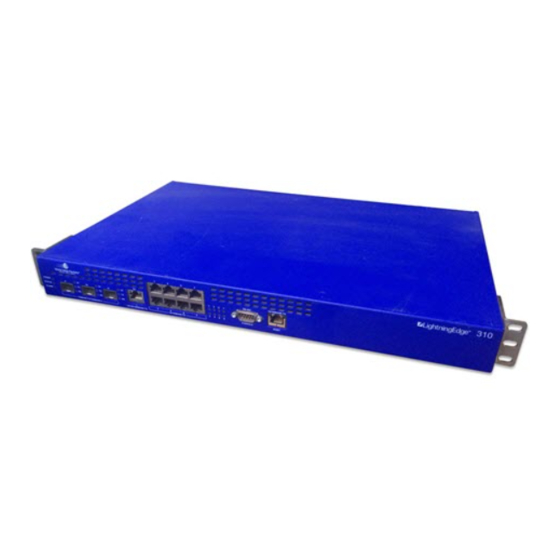
ESCRIPTION LE-427 The LE-427 has 16 1000 Mbps SFP ports and has the same 1 RU height as most of the other devices. Status LEDs for the 1000 Mbps ports are located immediately above each port. The unit status LEDs are located on the left side of the device. -
Page 23: Leds
ARDWARE ESCRIPTION The LE-311, LE-311v, and LE-327 devices also include an external serial console port for RS-232 communication on the front of the device labeled RS-232 Console. The console port can be used to attach a terminal or a PC to the device for out-of-band management. The RS-232 port connector utilizes a standard DB-9 connector that follows standard DTE wiring pin assignment. - Page 24 ARDWARE ESCRIPTION The unit status LEDs communicate system operational status. They are located to the left of the 1000BASE-X ports, as seen in the following graphic. POWER STATUS ALARM Figure 1-5: Unit status LEDs Table 1-4: Unit status LEDs, 3.0 System Software State Indication POWER...
- Page 25 Port is active and available for use. Port is transmitting 802.3x flow control Pause Frames. The LEDs on the LE-427 are located above each port. These LEDs indicate the status of each of the Gigabit ports. Table 1-6: 100BASE-TX Status LEDs...
-
Page 26: Power Supply
Ethernet packets. Power Supply The AC power supply for all models, except the LE-427, operates from 90-240 VAC, drawing 1.5- .75 Amps AC, 50/60 Hz. The DC power supply operates from -38 VDC to -72 Volts VDC. LE-3xx/LE-4xx Hardware Installation & User Guide... -
Page 27: Fans
LE-31 1, LE-31 1v, LE-327, and LE-427 Power Supply The power supplies on the LE-311, LE-311v, LE-327, and LE-427 are 1+1 redundant and can be hot swapped. The LE-311, LE-311v, LE-327, and LE-427 can also be ordered with pluggable DC power supplies. - Page 28 EFAULT ONFIGURATION LE-3xx/LE-4xx Hardware Installation & User Guide...
-
Page 29: Chapter 2: Getting Started
Chapter Getting Started • • • • • • At a Glance: • Package Contents • Removable Power Supplies • Power Supply LED • Power Cord and Power Cord Restraints • Power Supply LED Power Supply Fan • Installing an AC Power Supply •... -
Page 30: Installing The Scs/Sds Device
SCS/SDS D NSTALLING THE EVICE Installing the SCS/SDS Device The SCS/SDS device can be mounted in a standard equipment rack that has been properly mounted to the building infrastructure or it can be placed on a desktop. Read all installation instructions before connecting LightningEdge WARNING: devices to a power source. -
Page 31: Dc Power Connections
SCS/SDS D NSTALLING THE EVICE Affix the self-adhesive rubber feet to the bottom of the SCS/SDS, near the corners. Place the device in the desired location on shelf or tabletop. Leave adequate space in front and behind the device for cable attachments and cooling vents. For AC devices, connect the AC power cord to the device, then plug it into a power source. - Page 32 を確認してください。DC 回路に対するパネル基板のブレーカを OFF の位置に します。回路が誤って接続されないよう、ブレーカのスイッチを OFF の位置 にテープで止めてください。 NOTE: Ciena/World Wide Packets recommends that 14-AWG copper conductors be used for the DC-input wires and 10 - 12 AWG copper conductor for the ground wire. Connecting to a DC power source Verify that power is off to the DC-input circuit.
- Page 33 SCS/SDS D NSTALLING THE EVICE Wire the DC-input power supply to the J-9 terminal connector (supplied) according to the label on the outside of the chassis (see Figure 2-2 ), ensuring that all connections are secure: Connect the -48V input wire to the -48V_A pin. •...
-
Page 34: Removable Power Supplies
This section provides instructions for installing the power supplies into an LE-310, LE-311, LE- 311v, LE-327, and LE-427 devices. In general, the DC power supply has the same characteristics as the AC version. When two power supplies are installed, the power supplies provide system power simultaneously (load sharing). -
Page 35: Power Cord And Power Cord Restraints
OWER ORD AND OWER ESTRAINTS VARNING: Håll händer och fingrar borta från strömaggregaten eftersom strömställarplattan är strömförande när systemet är i bruk. DUTCH: Houd uw handen en vingers uit de buurt van de voedingscompartimenten wanneer het systeem functioneert en de achterkant van de ethernetswitch onder spanning staat. - Page 36 For devices with a fixed power supply, a cord saddle retainer is snapped into the fan outlet grid. For devices with removable power supplies, a twistable cord retainer is used. Contact Ciena/World Wide Packets Sales to purchase these retainer clips.
-
Page 37: Power Supply Led
OWER UPPLY Twistable Cord Retainer Installation (removable power supplies): Figure 2-5: Twistable Cord Retainer Installation Twist one end of the retainer around the handle of the power supply (see Figure Plug the power cord firmly into the device's power receptacle. Twist the other end of the clip around the power cord as shown in Figure 2-5 The power cord may now be plugged into a power source. - Page 38 AC P NSTALLING AN OWER UPPLY Um Schäden durch statische Entladungen an den WARNUNG: Elektronikkomponenten zu vermeiden, tragen Sie bei der Handhabung der Module oder wenn Sie mit internen Komponenten von SDS/SCS in Kontakt geraten stets eine Erdungsmanschette am Handgelenk. Pour empêcher la détérioration des composants AVERTISSEMENT: électroniques due aux pointes de tension, veillez toujours à...
-
Page 39: Removing An Ac Power Supply
AC P EMOVING AN OWER UPPLY Removing an AC Power Supply Disconnect the power cord from the power source and from the power supply. Use a phillips screwdriver to loosen the power supply’s two captive hold-down screws. Grasp the power supply handle and pull the supply straight out of the slot, supporting the supply with your other hand. - Page 40 DC P NSTALLING A OWER UPPLY prima di eseguire la procedura assicurarsi che l'alimentazione al circuito Italian: CC sia spenta. Individuare l'interruttore di sicurezza sul quadro strumenti che alimenta il circuito CC e portarlo in posizione OFF. Fissare la leva dell'interruttore di sicurezza in posizione OFF con nastro adesivo per impedire la chiusura accidentale del circuito.
-
Page 41: Removing A Dc Power Supply
DC P EMOVING A OWER UPPLY WARNUNG: Wenn Sie an der Klemmleiste Leitungen anschließen, stellen Sie sicher, dass keine abstehenden Litzenadern der angeschlossenen Leitung mit anderen Teilen der Klemmleiste in Kontakt geraten. AVERTISSEMENT: Lors de procédures de branchement au bloc de jonction, veillez à... - Page 42 DC P EMOVING A OWER UPPLY schalten Sie diesen in die AUS-Stellung (OFF). Fixieren Sie den Schalthebel des Trennschalters mit Klebeband in der AUS-Position, um ein versehentliches Einschalten zu vermeiden. AVERTISSEMENT: Avant d’effectuer la procédure, assurez-vous de la mise hors tension complète du circuit en courant continu.
-
Page 43: Transceiver Installation
RANSCEIVER NSTALLATION Use a phillips screwdriver to loosen the power supply’s two captive hold-down screws. Grasp the power supply handle and pull the supply straight out of the slot, supporting the supply with your other hand. Install a cover plate if the bay is to remain empty for any length of time. Transceiver Installation Each LE-4xx SCS has 16 slots available for Gigabit Ethernet small form factor pluggable (SFP) optics. -
Page 44: Cable Installation And Guidelines
ABLE NSTALLATION AND UIDELINES Gently pull on the optic to make sure that it has seated properly. WARNING: Optic operation should be verified by observing the status LEDs. Do not look into the laser to verify operation. For additional laser safety information, refer to Appendix B, Regulatory Compliance and Safety. -
Page 45: Connecting Cables To The Device
ABLE NSTALLATION AND UIDELINES This guide assumes that the site's data cables have been properly installed in a centrally wired distribution configuration. When installing fiber optics cables and other network cabling, always have them installed and tested by a technician who is certified by the Electronics Industry Association/Telecommunications Industry Association (EIA/TIA). -
Page 46: Initial Configuration
10BASE-T/100BASE-TX Ethernet uses four wires to communicate, leaving four wires unused. However, all four pairs should be terminated. While Cat 5 cable is sufficient, Ciena/World Wide Packets recommends using Category 5e+ cable or better. All Ethernet cables must be shielded to meet the class B radiated emissions requirements. - Page 47 NITIAL ONFIGURATION réseau, la communication avec l'appareil risque de ne plus être possible. Si toutes les autres méthodes de dépannage ont été essayées, une récupération peut être tentée à l’aide du bouton Reset. VARNING: Var försiktig när du anger IP-adressen eller subnätmasken eftersom det nya värdet verkställs omedelbart.
- Page 48 NITIAL ONFIGURATION LE-3xx/LE-4xx Hardware Installation & User Guide...
-
Page 49: Chapter 3: Troubleshooting
Chapter Troubleshooting • • • • • • At a Glance: LED POST Error Conditions • Troubleshooting Checklist • Reset Button • This section provides information that will help solve problems that may occur with LE-3xx SCS/SDS and LE-4xx SCS devices. For information on troubleshooting specific appliances, refer to their respective user manuals. - Page 50 LED POST E RROR ONDITIONS Table 3-1: LED Error Conditions ON/OFF/6 blinks Flash failed. Cannot use file system or Unit will reboot download application files. ON/OFF/7 blinks System image missing or bad checksum. Unit will reboot Cannot load operating system. POST 2 PWR/STATUS/ Indication...
-
Page 51: Troubleshooting Checklist
ROUBLESHOOTING HECKLIST Troubleshooting Checklist Table 3-2: Troubleshooting Checklist If the problem is: Do the following: No link Make sure the port connections are securely connected. Make sure all optics are properly installed. If using the patch panel, verify that the connectors are properly installed. - Page 52 ROUBLESHOOTING HECKLIST Table 3-2: Troubleshooting Checklist Power loss Check to ensure power outage was not due to breaker or outlet operation by checking for tripped breakers and/or the outlet's ground fault indicator (GFI). If a breaker or GFI is tripped, reset it and check the device for power restoration.
-
Page 53: Reset Button
ESET UTTON Table 3-2: Troubleshooting Checklist Unit does not boot (Status LED is off or Disconnect the device blinks for more than 5 minutes) from its power source at the wall outlet. After 10 seconds, plug the power cable back into the wall outlet. - Page 54 ESET UTTON A small unlabeled hole to the right of the MGMT port provides access to a reset button just inside the chassis. Inserting a small flat-tipped object, such as a straightened paper clip, and pressing the reset button causes the LE-4xx SCS to perform one of the following: Pushing the reset button one time will shut down and reboot the device.
- Page 55 ESET UTTON UPOZORNENIE: Vynulovanie systému by sa malo vykona″ IBA ak všetky ostatné snahy na vyriešenie problému zlyhali. Stlaèením tlaèidla Reset (Vynulovanie) rebootujete procesor jednotky. Vymaže sa flash pamä″ vrátane dát aplikácie a konfigurácie. Zariadenie sa vráti na základné výrobné nastavenie. Efetue a reinicialização do sistema SOMENTE quando todas as ADVERTÊNCIA: outras tentativas de solução do problema falharem.
- Page 56 ESET UTTON The device will then begin System shutdown, which could take as long as 2 minutes if the system is busy, during which time the Power LED will blink. If a system reset fails to correct the problem, a Reset to Factory Defaults can be attempted.
-
Page 57: Appendix A: Technical Specifications
Appendix Technical Specifications • • • • • • Device Specifications For LE-3xx SCS/SDS and LE-4xx SCS devices: Table A-1: Specifications Feature Specification Fault Tolerance Redundant fans and power supplies (optional) Power System AC Input Power LE-310: 100-240 VAC All others 85-264 VAC, 47/63 Hz, Amps: LE-310, 0.6/0.3;... -
Page 58: Power Consumption
44.2 mm H x 444.5 mm W x 393.7 mm D (1.74 in H x 17.5 in W x 15.5 in) LE-327/LE-427 44.2 mm H x 444.5 mm W x 368.3 mm D (1.74 in H x 17.5 in W x 14.5 in) Weight LE-310: 9 lbs (4.08 kg) - Page 59 57.6 LE-311/311v Min Load 55.8 55.2 57.6 Max Load 63.9 63.6 64.8 LE-327 Min Load 66.3 66.5 67.7 Max Load 91.8 90.7 91.0 LE-427 Min Load 79.2 82.8 100.8 Max Load 93.6 98.4 115.2 LE-3xx/LE-4xx Hardware Installation & User Guide...
-
Page 60: Snmp Traps
SNMP T RAPS SNMP Traps The following table lists standard SNMP traps on the device. Table A-3: SNMP Traps Trap MIB Type Description Cold Start MIB II Trap generated after device successfully reboot. Authentication Failure MIB II Trap generated when values are attempted to be set using incorrect community string. -
Page 61: Console Port Pin Assignments
ONSOLE SSIGNMENTS Console Port Pin Assignments The RS-232 serial console port located on the front of the device uses a common 9-pin, D-type connector for attachment. The DB-9 connector on the device is a male connector. The cord used to connect to the device should be a standard null modem cable with a female DB-9 connector. - Page 62 ONSOLE SSIGNMENTS LE-3xx/LE-4xx Hardware Installation & User Guide...
-
Page 63: Appendix B: Regulatory Compliance And Safety
Appendix Regulatory Compliance and Safety • • • • • • This chapter lists the different agency approval declarations for LE-3xx SCS/SDS and LE-4xx SCS devices. It also includes installation safety notes. Table B-1: Regulatory Approval Declarations Issue Approval Declaration Safety UL 60950-1:2003, First Edition IEC 60950-1 (2001) First Edition... - Page 64 LASS ASER RODUCT Laserproduct van Klasse 1. WAARSCHUWING: Klasse 1 laserprodukt. ADVARSEL: prodotto laser della Classe 1. AVVERTENZA: Laserový produkt triedy 1. UPOZORNENIE: ADVERTÊNCIA: Produto a laser classe 1. 警告:Class 1 レーザー製品です。 WARNING: Install only lasers that have been demonstrated to meet Class 1 eye safe levels by a Nationally recognized Authority(s) such as The Food and Drug administration's 21CFR1040 Laser Energy Source, UL 60950 Information Technology equipment and European norms EN60825-1 and EN60825-2.
-
Page 65: Radiation From Open Port Aperture
ADIATION FROM PERTURE Unnlater man å bruke laser transceivere som møter disse standardene, kan det føre til øyenskade for brukere eller vedlikeholdspersonell som arbeider rundt utstyret. AVVERTENZA: installare unicamente laser conformi ai livelli di sicurezza visiva della Classe 1 ai sensi dei criteri stabiliti da un ente nazionale preposto, ad esempio 21CFR1040 Sorgente di energia laser e UL 60950 apparecchiature informatiche della Food and Drug Administration oppure le norme EN60825-1 e EN60825-2 dell'UE. -
Page 66: Eu Declaration Of Conformity
目に見えない電磁波が放射されている場合がありますので、照射を受けない ようにし、また開口部を直接見ないようにしてください。 EU Declaration of Conformity A signed copy of the European Declaration of Conformity is available from Ciena/World Wide Packets headquarters office. Une copie signée de la Déclaration européenne de conformité est disponible dans les bureaux du siège de Ciena/World Wide Packets. -
Page 67: Fcc Statement
If necessary, the user should consult the dealer or an experienced radio/television technician for additional suggestions. Modifications to this product not authorized by Ciena/World Wide Packets could void the FCC approval and negate your authority to operate the product. LE-3xx/LE-4xx Hardware Installation & User Guide... -
Page 68: Fcc-Erklrung
Au besoin, l’utilisateur peut consulter le revendeur ou un technicien radio/télévision expérimenté pour obtenir d’autres suggestions. Toute modification apportée à ce produit non autorisée par Ciena/World Wide Packets peut entraîner l’annulation de l’approbation par la FCC et de votre droit d'utiliser le produit. -
Page 69: Fcc-Verklaring
Du bör vid behov rådfråga handlaren eller en erfaren radio-/tv-tekniker för ytterligare förslag. Ändringar i den här produkten som inte godkänts av Ciena/World Wide Packets kan medföra att produkten inte uppfyller FCC-kraven och att du inte längre har tillåtelse att använda produkten. -
Page 70: Oznámenie Fcc
Se necessário, o usuário deve consultar o vendedor ou um técnico de rádio/televisão experiente para sugestões adicionais. Modificações neste produto não autorizadas pela Ciena/World Wide Packets podem invalidar a aprovação da FCC e negar sua autoridade para operar o produto Oznámenie FCC... -
Page 71: Dichiarazione Fcc
Om nødvendig bør brukeren konsultere forhandleren eller en erfaren radio/televisjons-tekniker for ytterligere råd. Endringer av dette produktet som ikke er godkjente av Ciena/World Wide Packets kan ugyldiggjøre FCC-godkjennelsen og oppheve din autoritet til å bruke produktet. Dichiarazione FCC Quest'apparecchiatura è conforme al Comma 15 delle normative FCC. Il suo utilizzo è soggetto alle condizioni seguenti: L'apparecchiatura non deve provocare interferenze dannose. -
Page 72: Canada
機器と受信機の距離を離す。 受信機が接続されているコンセントとは回路が異なるコンセントに機器を接続する。 • 必要に応じてユーザーは販売店またはラジオ / テレビの専門技術者に問い合わせ指示を受けて てください。 Ciena/World Wide Packets に承認をうけずにこの製品に変更を加えると、FCC 認可が無効になり、 この製品を操作するユーザー似対する許可も無効となります。 Canada This Class B digital apparatus complies with Canadian ICES-003. Cet appareil numérique de la classe B est conforme à la norme NMB-003 du Canada. Le Présent appareil n'émet pas de bruits radioélectriques dépassant les limites applicables aux appareils de la classe B prescrites par le règlement de brouillage radioélectrique dicté... - Page 73 Abonnentporter på alle LE-3xx SCS/SDS- og LE-4xx SCS-enhetene er beregnet på sammenkobling bare innenfor leverandørens nettverk. Koblingen til flere leverandørers nettverk (eller PSTN - det offentlige svitsjede telefoninettet) kan gjøres med andre løsninger som er tilgjengelige fra Ciena/World Wide Packets produktfamilie. ATTENZIONE:...
-
Page 74: Safety Warning Translations
(alebo PSTN) sa dá uskuto č nit´ s pou itím iných riešení, ž ktoré sú dostupné v rámci produktov skupiny Ciena/World Wide Packets. CUIDADO: As portas do assinante em todos os dispositivos LE-3xx SCS/SDS e LE-4xx SCS destinam-se somente interconexo dentro da rede do provedor. A conexo a mltiplas redes de provedores (ou da RTPC) pode ser obtida por meio de outras solues disponveis na famlia de produtos Ciena/World Wide Packets. -
Page 75: Restricted Access Location/Qualified Personnel
ESTRICTED CCESS OCATION UALIFIED ERSONNEL WAARSCHUWING: Deze waarschuwing duidt op gevaar. U bevindt zich in een situatie die lichamelijk letsel kan veroorzaken. Voordat u met apparatuur aan de slag gaat, moet u zich bewust zijn van alle risico's die elektrische circuits opleveren en vertrouwd zijn met de standaardpraktijken om ongevallen te voorkomen. -
Page 76: Jewelry Removal
EWELRY EMOVAL Dette utstyret skal installeres i et Begrenset Adkomst Område (BAO) ADVARSEL: og kun vedlikeholdes av kvalifisert servicepersonale. AVVERTENZA: l'apparecchiatura deve essere installata in un luogo con ingresso vietato ai non addetti e la sua manutenzione deve essere affidata unicamente al personale di assistenza qualificato. -
Page 77: Installation
NSTALLATION ADVARSEL: Før du arbeider på utstyr som er koblet til kraftledninger, fjern smykker (inkludert ringer, kjeder og klokker). Metallobjekter vil varmes opp når du er koblet til strøm og jord, og det kan forårsake alvorlige forbrenninger, eller metallgjenstanden kan bli sveiset til terminalene. prima di intervenire sull'apparecchiatura collegata a una fonte di AVVERTENZA: alimentazione, togliersi qualsiasi monile (orologio, anelli, collane e braccialetti). -
Page 78: Equipment Stacking
QUIPMENT TACKING Leia as instruções de instalação antes de conectar o sistema à ADVERTÊNCIA: sua fonte de alimentação. 警告:システムを電源に接続する前にインストール手順をお読みください。 WARNING: Secure all power cabling when installing this unit to avoid disturbing field wiring connections. WARNUNG: Achten Sie bei der Installation dieses Geräts darauf, dass alle Stromkabel gesichert sind, um eine Unterbrechung der Feldverkabelung zu vermeiden. -
Page 79: Copper Conductors
OPPER ONDUCTORS WARNUNG: Achten Sie beim Gestelleinbau darauf, dass Sie keine anderen Gegenstände auf diesem Gerät platzieren. Die im Lieferumfang dieses Geräts enthaltenen Halteklammern sind ausschließlich für das Gewicht dieses Geräts ausgelegt. Bei einem Bruch aufgrund von Übergewicht kann es zu Personenschäden und Beschädigungen des Geräts kommen. -
Page 80: Maintenance
AINTENANCE When installing the unit, use copper conductors only. WARNING: Verwenden Sie bei der Installation des Geräts ausschließlich WARNUNG: Kupferleiter. AVERTISSEMENT: Lors de l’installation de l’unité, utilisez uniquement des conducteurs en cuivre. VARNING: Använd endast kopparledare när du installerar enheten. WAARSCHUWING: Gebruik voor de installatie van deze eenheid alleen koperen geleiders. - Page 81 AINTENANCE VARNING: Kontrollera att all ström är bortkopplad från enheten innan du utför underhåll på enheten. Dra ut strömsladden på alla växelströmsenheter. Kontrollera att all ström är av på likströmsenheter genom att leta reda på nätströmbrytaren på strömpanelen och slå AV (OFF) strömmen och tejpa fast strömbrytaren i läget AV (OFF).
-
Page 82: Dc Power Warnings
DC P OWER ARNINGS Bei der Installation oder Wartung des Geräts muss der Erdanschluss WARNUNG: immer als erstes an- und als letztes abgeklemmt werden. AVERTISSEMENT: Lors de l’installation ou de l'entretien de l'unité, la mise à la terre doit toujours être connectée en premier et déconnectée en dernier. VARNING: Jordledningen måste alltid göras först och kopplas från sist vid installation och underhåll på... - Page 83 DC P OWER ARNINGS VARNING: Lätt åtkomliga och korrekt märkta strömbrytare för likström måste installeras i den fasta kopplingen mellan likströmskällan i anläggningen och denna utrustning. Brytarna och kopplingen måste installeras av utbildad servicepersonal enligt alla lokala och nationella bestämmelser om elektricitet. Installeer goed toegankelijke gelijkstroomonderbrekers van WAARSCHUWING: de juiste nominale waarde in de vaste bedrading tussen de gelijkstroombron van...
- Page 84 DC P OWER ARNINGS Une fois l'alimentation en courant continu connectée, retirez AVERTISSEMENT: le ruban adhésif servant à bloquer l’interrupteur du disjoncteur et rétablissez le courant en plaçant l’interrupteur en position de marche (ON). VARNING: Ta bort tejpen från strömbrytaren när likströmskällan har anslutits och slå...
-
Page 85: Lightning Activity
IGHTNING CTIVITY AVVERTENZA: collegare l'unità esclusivamente a una presa di corrente continua rispondente ai requisiti SELV (Safety Extra-Low Voltage) in base alle norme di sicurezza EN60950 e UL 60950. UPOZORNENIE: Zariadenie pripájajte len k jednosmernému napájaniu, ktoré spåòa požiadavky na mimoriadnu bezpeènos″ – nízkonapä″ovú (SELV) v normách EN60950 a UL 60950 na základe bezpeènostných noriem. - Page 86 OWER UPPLY ISCONNECTION Before working on a chassis or working near power supplies, unplug WARNING: the power cord on AC units; disconnect the power at the circuit breaker on DC units. Ziehen Sie bei Wechselstromgeräten das Netzkabel bzw. WARNUNG: unterbrechen Sie bei Gleichstromgeräten die Stromzufuhr an der Gleichstromsicherung, bevor Sie am Gehäuse oder in der Nähe der Stromversorgung arbeiten.
-
Page 87: Rack Mounting And Servicing
OUNTING AND ERVICING AVERTISSEMENT: Il est possible que cette unité soit munie de plusieurs connexions électriques. Il faut donc débrancher ou éteindre toutes les connexions avant d’entreprendre toute maintenance. VARNING: Denna enhet har fler än en nätanslutning. Alla anslutningar måste tas bort eller avmagnetiseras före service. - Page 88 OUNTING AND ERVICING Jednotky SCS/SDS musia by″ nainštalované na stojane, ktorý je UPOZORNENIE: zaistený k stavebnej konštrukcii. ADVERTÊNCIA: Unidades SDS/SCS devem ser instaladas em um rack fixado na estrutura do prédio. 警告:SDS/SCS 装置は建物の構造に固定されたラックに設置しなければなりませ ん。 To prevent bodily injury when mounting or servicing this unit in a WARNING: rack, you must take special precautions to ensure that the system remains stable.
- Page 89 OUNTING AND ERVICING instructies van de fabrikant. Wanneer u de eenheid in een gedeeltelijk gevuld rek monteert, moet u het rek van beneden naar boven laden en de zwaarste component ondereen in het rek plaatsen. Als het rek met stabilisatoren is geleverd, moet u de stabilisatoren aanbrengen voordat u de eenheid in het rek aanbrengt of onderhoudt.
-
Page 90: Tn Power (Ac Units Only)
TN P (AC U OWER NITS を設置する際には、最も重いものが最下段になるよう、下から上へと設置を行っ てください。 ラックに安定器具が付属している場合には、本装置をラックに設 置、またはラック上での作業を行う前に安定器具を取り付けてください。 TN Power (AC Units Only) WARNING: The device is designed to work with TN power systems. Use only a power supply cord suitable for the application and subject to the country’s national code and regulations, bearing the appropriate safety mark. -
Page 91: Appendix C: Service And Support
Service and Support • • • • • • To receive technical support for the LightningEdge family of products, contact Ciena/World Wide Packets Customer Support using any of the following methods. Address Ciena Corporation 1201 Winterson Road Linthicum, MD 21090... - Page 92 ELEPHONE AND Telephone and Fax For technical support on the LightningEdge family of products contact the Ciena/World Wide Packets Technical Support department by phone or fax: North America 800-Ciena24 (1-800-243-6224) or 1-410-865-4961 EMEA 800-Ciena24-7 (800-243-6224-7) or +44-207-012-5508 APAC 800-Ciena24-7 (800-243-6224-7) or +81-3-3248-4743...
- Page 93 Condition refers to an occurrence within the found throughout Ciena/World Wide Packets system that exists for a period of time that may documentation. be of interest to the user or operator. A condition that persists for an extended period of time may be re-classified as an Event.
- Page 94 Spanning Tree Domains is used in a network that employs RSTP, a Spanning Tree Domain Ingress refers to network traffic entering a limits the reach of RSTP to certain areas of the network device or the point on a device where network.
Need help?
Do you have a question about the LE-427 and is the answer not in the manual?
Questions and answers