Advertisement
Table of Contents
Harbor Breeze® is a registered trademark
of LF, LLC. All Rights Reserved.
ATTACH YOUR RECEIPT HERE
Serial Number _________________________
Questions, problems, missing parts? Before returning to your retailer, call our customer
service department at 1-800-643-0067, 8 a.m. - 6 p.m., EST, Monday - Thursday, 8 a.m. - 5 p.m.,
EST, Friday.
EB1690
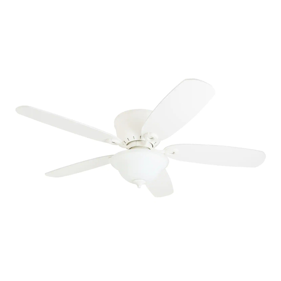
PAWTUCKET CEILING FAN
Purchase Date _________________________
1
ITEM #0803775, 0721899, 0807427
MODEL #40958, 40959, 40047
Español p. 20
Advertisement
Table of Contents

Related Manuals for Harbor Breeze 40959


Summary of Contents for Harbor Breeze 40959
- Page 1 ITEM #0803775, 0721899, 0807427 PAWTUCKET CEILING FAN MODEL #40958, 40959, 40047 Español p. 20 Harbor Breeze® is a registered trademark of LF, LLC. All Rights Reserved. ATTACH YOUR RECEIPT HERE Serial Number _________________________ Purchase Date _________________________ Questions, problems, missing parts? Before returning to your retailer, call our customer service department at 1-800-643-0067, 8 a.m.
-
Page 2: Table Of Contents
TABLE OF CONTENTS Package Contents . . . . . . . . . . . . . . . . . . . . . . . . . . . . . . . . . . . . . . . . . . . . . . . . . . . . . . . . . . . . . . . . . 3 Hardware Contents . -
Page 3: Package Contents
PACKAGE CONTENTS PART DESCRIPTION QUANTITY Motor Housing Upper Mounting Bracket Receiver (preassembled to Upper Mounting Bracket [B]) Lower Mounting Bracket (preassembled to Motor [E]) Motor Switch Housing (preassembled to Motor [E]) Switch Housing Cap (preassembled to Light Kit [H]) Light Kit Finial Cap (preassembled to Light Kit [H]) Finial (preassembled to Light Kit [H]) Glass Shade... -
Page 4: Hardware Contents
HARDWARE CONTENTS (shown actual size) Plug Button Blade Screw Blade Washer Wire Connector Qty . 1 Qty . 15 Qty . 15 Qty . 2 + 1 extra + 1 extra... -
Page 5: Safety Information
SAFETY INFORMATION Please read and understand this entire manual before attempting to assemble, operate or install the product . • Before you begin installing the fan, disconnect the power by removing fuses or turning off the circuit breakers . • Make sure all electrical connections comply with local codes, ordinances, the National Electrical Code and ANSI/NFPA 70-199. Hire a qualified electrician or consult a do-it-yourself wiring handbook if you are unfamiliar with installing electrical wiring . • Make sure the installation site you choose allows a minimum clearance of 7 ft . -
Page 6: Preparation
SAFETY INFORMATION CAUTION: Read all instructions and safety information before installing your new fan . Review the accompanying assembly diagrams . CAUTION: Be sure the outlet box is properly grounded or that a ground (green or bare) wire is present . CAUTION: Carefully check all screws, bolts and nuts on the fan motor assembly to ensure they are secured . -
Page 7: Initial Installation
INITIAL INSTALLATION 1 . Turn off the circuit breakers and the wall switch to the fan supply line leads . DANGER: Failure to disconnect the power supply prior to installation may result in serious injury or death . 2 . Ensure the blades (M) will be at least 30 in . from any obstructions and will be at least 7 ft. above the floor. - Page 8 INITIAL INSTALLATION WARNING: To reduce the risk of fire, electrical shock or personal injury, wire connectors provided with this fan are designed to accept only one 12-gauge house wire and two lead wires from the fan . If your house wire is larger than 12-gauge and/or there is more than one house wire to connect to the two fan lead wires, consult an electrician for the proper size wire connectors to use .
- Page 9 INITIAL INSTALLATION 7 . Remove the mounting bracket screws (R) and spring washers (W) from underneath the lower mounting bracket (D) . Also remove the motor screws (V) from the bottom of the motor (E) . Retain for later use . Note: Make sure to keep loose hardware separate to avoid confusion during installation .
-
Page 10: Fan Wiring
FAN WIRING WARNING: To reduce the risk of fire, electrical shock or personal injury, wire connectors provided with this fan are designed to accept only one 12-gauge house wire and two lead wires from the fan . If your house wire is larger than 12-gauge and there is more than one house wire to connect to the two fan lead wires, consult an electrician for the proper size wire connectors to use . -
Page 11: Final Installation
FINAL INSTALLATION 1 . Temporarily lift the motor housing (A) to the upper mounting bracket (B) to determine which two motor housing screws (T) in the sides of the upper mounting bracket (B) align with the slotted holes in the top edge of the motor housing (A) . - Page 12 FINAL INSTALLATION 4 . Install the blade arm (L) to the underside of the motor (E) with motor screws (V) previously removed (Step 7, page 9) . Tighten with Phillips screwdriver . Repeat for each blade arm (L) . Note: If you wish to install the fan without the light kit, proceed to Step 10.
- Page 13 FINAL INSTALLATION 7 . Install bulbs (N) into the sockets on the light kit (H) . Important: Make sure you allow the bulbs (N) and light kit (H) to cool before you replace the bulbs . 8 . Remove the preassembled large washer (P), hex nut (Q), finial cap (I) and finial (J) from the light kit (H).
- Page 14 FINAL INSTALLATION 10 . To install the fan without the light kit (H), remove Hex Nut Lock Washer the hex nut and lock washer from the rod on the inside of the switch housing cap (G) . Remove light kit (H) from the switch housing cap (G) and discard, then install the plug button (AA) into the center hole of the switch housing cap (G) .
-
Page 15: Operating Instructions
OPERATING INSTRUCTIONS 1 . Remove the battery cover from the back of the remote found in remote pack (O) . Insert the battery from Remote remote pack (O) into the remote; ensure polarity of battery matches the polarity indicated in the battery compartment -- positive (+) to positive (+) and negative Battery (-) to negative (-) . -
Page 16: Care And Maintenance
CARE AND MAINTENANCE At least twice each year, tighten all screws on the fan . Clean the motor housing with only a soft brush or lint-free cloth to avoid scratching the finish. Bulb Replacement: Use 60-watt max . E26-base LED, CFL or incandescent bulbs . Halogen bulbs are not recommended for this item . - Page 17 TROUBLESHOOTING PROBLEM POSSIBLE CAUSE CORRECTIVE ACTION 1 . The blades are loose . 1 . Check and tighten all screws that hold the fan blades to the blade arms and the motor . 2 . There is a cracked blade . 2 .
-
Page 18: Limited Lifetime Warranty
LIFETIME LIMITED WARRANTY The manufacturer warrants this fan to be free from defects in workmanship and materials present at time of shipment from the factory for a lifetime from the date of purchase by the original purchaser . The retailer also warrants that all other fan parts, excluding any glass or plastic blades, to be free from defects in workmanship and material at the time of shipment from the factory for a period of one year after the date of purchase by the original purchaser . -
Page 19: Replacement Parts List
REPLACEMENT PARTS LIST For replacement parts, call the customer service department at 1-800-643-0067, 8 a .m . - 6 p .m ., EST, Monday - Thursday, 8 a .m . - 5 p .m ., EST, Friday . PART DESCRIPTION #0803775 #0721899 #0807427...
Need help?
Do you have a question about the 40959 and is the answer not in the manual?
Questions and answers