Advertisement
Table of Contents
- 1 Table of Contents
- 2 Package Contents
- 3 Hardware Contents
- 4 Safety Information
- 5 Preparation
- 6 Initial Installation
- 7 Standard or Angle Mounting Instructions
- 8 Closemount Installation
- 9 Wiring
- 10 Final Installation
- 11 Operating Instructions
- 12 Care and Maintenance
- 13 Troubleshooting
- 14 Limited Lifetime Warranty
- 15 Replacement Parts List
- Download this manual
Harbor Breeze® is a registered trademark
of LF, LLC. All Rights Reserved.
ATTACH YOUR RECEIPT HERE
Purchase Date ___________________________
Questions, problems, missing parts? Before returning to your retailer, call our customer
service department at 1-800-643-0067, 8 a.m. - 6 p.m., EST, Monday - Thursday, 8 a.m. - 5 p.m.,
EST, Friday.
AB171039
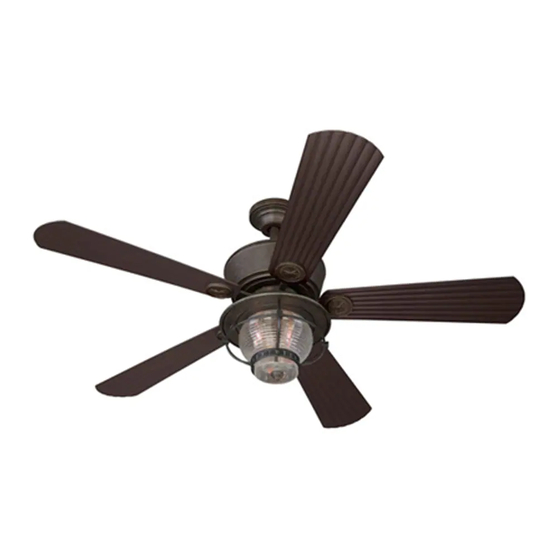
MERRIMACK CEILING FAN
1
ITEM #0080443
MODEL #40942
Español p. 24
LISTED FOR
WET LOCATION
Advertisement
Table of Contents

Related Manuals for Harbor Breeze MERRIMACK 40942


Summary of Contents for Harbor Breeze MERRIMACK 40942
- Page 1 ITEM #0080443 MERRIMACK CEILING FAN MODEL #40942 Español p. 24 Harbor Breeze® is a registered trademark of LF, LLC. All Rights Reserved. LISTED FOR WET LOCATION ATTACH YOUR RECEIPT HERE Purchase Date ___________________________ Questions, problems, missing parts? Before returning to your retailer, call our customer service department at 1-800-643-0067, 8 a.m.
-
Page 2: Table Of Contents
TABLE OF CONTENTS Package Contents ..............3 Hardware Contents . -
Page 3: Package Contents
PACKAGE CONTENTS PART DESCRIPTION QUANTITY Mounting Bracket (preassembled to Canopy [B]) Canopy Canopy Cover (preassembled to Canopy [B]) Yoke Cover Downrod Downrod Clip (preassembled to Downrod [E]) Downrod Pin (preassembled to Downrod [E]) Blade Arm Blade Medallion Glass Globe Blade Motor Assembly Fitter Plate (preassembled to Motor Assembly [L]) Light Pan... -
Page 4: Hardware Contents
HARDWARE CONTENTS (shown actual size) Wire Connector Blade Screw Motor Screw Qty. 3 + 1 extra Qty. 15 + 1 extra 1 extra... -
Page 5: Safety Information
SAFETY INFORMATION Please read and understand this entire manual before attempting to assemble, operate or install the product. • Before you begin installing the fan, disconnect the power by removing fuses or turning off the circuit breakers. • Make sure all electrical connections comply with local codes, ordinances, the National Electrical Code and ANSI/NFPA 70-199. Hire a qualified electrician or consult a do-it-yourself wiring handbook if you are unfamiliar with installing electrical wiring. -
Page 6: Preparation
SAFETY INFORMATION CAUTION: Read all instructions and safety information before installing your new fan. Review the accompanying assembly diagrams. CAUTION: Be sure the outlet box is properly grounded or that a ground (green or bare) wire is present. CAUTION: Carefully check all screws, bolts and nuts on the fan motor assembly to ensure they are secured. -
Page 7: Initial Installation
INITIAL INSTALLATION 1. Turn off the circuit breakers and the wall switch to the fan supply line leads. DANGER: Failure to disconnect the power supply prior to installation may result in serious injury or death. 2. Determine the mounting method to use. Standard mounting is best suited for ceilings 8 ft. - Page 8 INITIAL INSTALLATION 4. Loosen all four mounting brackets screws (Z), then completely remove the two mounting bracket screws (Z) from the round holes of canopy (B). Set aside for later use. Note: Make sure to keep loose hardware separate to avoid confusion during installation.
-
Page 9: Standard Or Angle Mounting Instructions
STANDARD OR ANGLE MOUNTING INSTRUCTIONS 1. Partially loosen the two set screws (X) in the yoke at the top of the motor assembly (L) to allow for installation of the downrod (E). Yoke 2. Remove the downrod clip (F) and downrod pin (G) from the downrod (E). - Page 10 STANDARD OR ANGLE MOUNTING INSTRUCTIONS 4. If installing the fan outdoors (optional), feed the fan wires through the holes in the downrod gasket (U). Then, slide the downrod gasket (U) over the top of the downrod (E). Note: If installing indoors, discard the downrod gasket (U) and proceed to step 5.
-
Page 11: Closemount Installation
CLOSEMOUNT INSTRUCTIONS 1. Remove and discard the canopy cover (C) from the bottom of the canopy (B). Note: The downrod (E) and canopy cover (C) are not used in this type of installation. 2. If installing the fan outdoors (optional), feed the fan wires and antenna from yoke of the motor assemby (L) through the holes in the yoke gasket (T) and the canopy (B). - Page 12 CLOSEMOUNT INSTRUCTIONS 4. Raise the fan and place the canopy (B) on the hook on the mounting bracket (A), temporarily leaving hands free for the wiring process.
-
Page 13: Wiring
WIRING WARNING: To reduce the risk of fire, electrical shock or personal injury, wire connectors provided with this fan are designed to accept only one 12-gauge house wire and two lead wires from the fan. If your house wire is larger than 12 gauges and/or there is more than one house wire to connect to the two fan lead wires, consult an electrician for the proper size wire connectors to use. -
Page 14: Final Installation
FINAL INSTALLATION Helpful Hint: The downrod (E), canopy cover (C) and yoke cover (D) are not used in this type of installation. 1. Align the canopy (B) over the loose mounting bracket screws (Z) preassembled on mounting bracket (A). Place the keyholes of the canopy (B) onto the mounting bracket screws (Z) and rotate the canopy (B) clockwise. - Page 15 FINAL INSTALLATION 4. Install the blade arm (H) to the underside of the motor assembly (L) with motor screws (Y) previously removed (Step 6, page 8). Tighten with Phillips screwdriver (not included). Repeat for each blade arm (H). 5. Remove one of the three fitter plate screws (AB) from the fitter plate (M) and save. Loosen but do not remove the other two fitter plate screws (AB).
- Page 16 FINAL INSTALLATION 7. Remove one light pan screw (AC) from one of the three brackets below the light pan (N) and save. Loosen but do not remove the other two screws on the other two brackets. Note: Make sure to keep loose hardware separate to avoid confusion during installation.
- Page 17 FINAL INSTALLATION 10. Install the bulbs (W) into the sockets on the light kit (O). Then remove the finial (R), rubber washer (P) and hex nut (Q). 11. Lift the glass globe (J) over the threaded rod on light kit (O). Re-install rubber washer (P) and hex nut (Q), securing with finial (R).
- Page 18 FINAL INSTALLATION 13.Remove the battery cover from the back of the Remote remote found in remote pack (V). Insert the battery from remote pack (V) into the remote; ensure LED Indicator polarity of battery matches the polarity indicated in the battery compartment -- positive (+) to positive (+) and negative (-) to negative (-).
-
Page 19: Operating Instructions
OPERATING INSTRUCTIONS 1. To operate the fan using the remote, press and release the following buttons: 1 - High fan speed LED Indicator 2 - Medium fan speed 3 - Low fan speed 4 - Fan Power - Turns the fan off. Light Delay Off mode - Press and hold the fan power button (4) for five seconds, which will turn off light after one minute. -
Page 20: Care And Maintenance
CARE AND MAINTENANCE At least twice each year, tighten all screws on the fan. Clean the motor housing with only a soft brush or lint-free cloth to avoid scratching the finish. Clean the blades with a lint-free cloth. Bulb Replacement: Use 40-watt max. candelabra-base bulbs or CFL equivalent. Battery Replacement for Remote: Use A23 12-volt battery. Important: Shut off the main power supply before you begin any maintenance tasks. - Page 21 TROUBLESHOOTING PROBLEM POSSIBLE CAUSE CORRECTIVE ACTION 1. The blades are loose. 1. Check and tighten all screws that hold the fan blades to the blade arms and the motor. 2. There is a cracked blade. 2. Replace the cracked blade. 3.
-
Page 22: Limited Lifetime Warranty
LIFETIME LIMITED WARRANTY The manufacturer warrants this fan to be free from defects in workmanship and materials present at time of shipment from the factory for a lifetime from the date of purchase by the original purchaser. The retailer also warrants that all other fan parts, excluding any glass or plastic blades, to be free from defects in workmanship and material at the time of shipment from the factory for a period of one year after the date of purchase by the original purchaser. -
Page 23: Replacement Parts List
REPLACEMENT PARTS LIST For replacement parts, call the customer service department at 1-800-643-0067, 8 a.m. - 6 p.m., EST, Monday - Thursday, 8 a.m. - 5 p.m., EST, Friday. PART DESCRIPTION PART # Mounting Bracket 4L000002480 Canopy 4L000002490 Canopy Cover 4L000002500 Yoke Cover 4L000002510...
Need help?
Do you have a question about the MERRIMACK 40942 and is the answer not in the manual?
Questions and answers