Table of Contents
Advertisement
Quick Links
Download this manual
See also:
Reference Manual
^1
USER'S MANUAL
^2
Power PMAC
Single Source Machine Control
21314 Lassen St. Chatsworth, CA 91311 // Tel. (818) 998-2095 Fax. (818) 998-7807 //
^3
Power PMAC User's Manual
^4
050-PRPMAC-0U0
^
5
January 6, 2015
..............................................................................
DELTA TAU
Data Systems, Inc.
NEW IDEAS IN MOTION ...
Power // Flexibility // Ease of Use
www.deltatau.com
Advertisement
Table of Contents

Related Manuals for Delta Tau Power PMAC


Summary of Contents for Delta Tau Power PMAC
- Page 1 USER’S MANUAL Power PMAC Power PMAC User’s Manual 050-PRPMAC-0U0 January 6, 2015 DELTA TAU Data Systems, Inc. NEW IDEAS IN MOTION … ……………………………………………..…...………………. Single Source Machine Control Power // Flexibility // Ease of Use 21314 Lassen St. Chatsworth, CA 91311 // Tel. (818) 998-2095 Fax. (818) 998-7807 //...
- Page 2 Copyright Information © 2015 Delta Tau Data Systems, Inc. All rights reserved. This document is furnished for the customers of Delta Tau Data Systems, Inc. Other uses are unauthorized without written permission of Delta Tau Data Systems, Inc. Information contained in this manual may be updated from time-to-time due to product improvements, etc., and may not conform in every respect to former issues.
- Page 3 Power PMAC User’s Manual Safety Instructions Qualified personnel must transport, assemble, install, and maintain this equipment. Properly qualified personnel are persons who are familiar with the transport, assembly, installation, and operation of equipment. The qualified personnel must know and observe the following standards and regulations: IEC364resp.CENELEC HD 384 or DIN VDE 0100...
-
Page 4: Updating The Manual For Firmware Version 1.6 Release
Power PMAC User’s Manual REVISION HISTORY REV. DESCRIPTION DATE APPVD New Manual Generated 11/28/2011 Curt Wilson Updating Table of Contents 01/19/2012 Curt Wilson Updating the manual for firmware version 1.5 release 08/10/2012 Curt Wilson Updating the manual for firmware version 1.6 release... -
Page 6: Table Of Contents
Power PMAC User’s Manual TABLE OF CONTENTS Contents POWER PMAC FAMILY OVERVIEW ....................27 What Is Power PMAC? ..........................27 Power PMAC Configurations ........................27 Power UMAC............................27 Compact Power UMAC ......................... 28 Power PMAC Etherlite .......................... 28 Power Brick Configurations ........................28 Power Clipper ............................ - Page 7 Power PMAC User’s Manual Communicating with the Power PMAC Control Application ..............42 Establishing Communications with the IDE ....................44 Startup Communications Control Window .................... 44 Embedded Communications Control Window ..................45 Changing the Power PMAC IP Address ....................46 Finding an Unknown IP Address ......................
- Page 8 Power PMAC User’s Manual SETTING UP THE MACRO RING ....................... 75 MACRO Ring Overview ..........................75 Power PMAC MACRO Interfaces ......................75 ACC-5E MACRO Interface for UMAC ....................75 ACC-5E3 MACRO Interface for UMAC ....................75 ACC-5EP3 MACRO Interface for Etherlite ................... 76 MACRO Interface for Power Brick .......................
- Page 9 Commutation Addresses ........................93 Setting Up a Motor as a Network Slave ...................... 95 Command Modes ........................... 95 Coordinating Power PMAC Motor Setup ....................96 Network-Slave Power PMAC Motor Setup .................... 99 SETTING UP FEEDBACK AND MASTER POSITION SENSORS ..........102 Setting Up Digital Quadrature Encoders ....................
- Page 10 Power PMAC User’s Manual Signal Format ............................163 Hardware Setup ........................... 163 Hardware Control Parameter Setup ....................163 Using the Resulting Position Information ................... 164 Setting Up Analog Data Position Inputs ....................166 Signal Format ............................166 Hardware Setup ........................... 167 Hardware Control Parameter Setup ....................
- Page 11 Amplifier Enable Flag Address: Motor[x].pAmpEnable, AmpEnableBit..........215 Absolute Power-On Position Address: Motor[x].pAbsPos ..............216 Is Power PMAC Commutating or Closing the Current Loop for This Motor? ......... 217 Setting Up Power PMAC for Velocity or Torque Control ............... 217 Hardware Setup ........................... 217 ASIC Programmable Signal Setup .......................
- Page 12 Establishing a Phase Reference (Synchronous Motors)................270 Absolute Phasing Reads ........................272 Correcting an Approximate Phase Reference..................278 Finishing Setting Up Power PMAC Commutation (Direct PWM or Sine Wave), Asynchronous (Induction) Motors ............................ 279 Calculating Motor[x].DtOverRotorTc Slip Constant ................279 Setting Motor[x].IdCmd Magnetization Current .................
- Page 13 Power PMAC User’s Manual Standard Servo Algorithm ........................293 Polynomial Filters ..........................293 Integration Mode ..........................296 Friction Feedforward .......................... 296 Acceleration Feedback ........................296 Input Deadband Compensation ......................296 Output Hysteretic Deadband ....................... 298 Adaptive Servo Control ..........................299 Selecting the Adaptive Control Algorithm ...................
- Page 14 Power PMAC User’s Manual SETTING UP COMPENSATION TABLES ..................332 Table Data Structure ..........................332 Reserving Memory for the Tables ......................333 Defining the Table Structure ........................334 Dimension Indices ..........................334 Number of Active Dimensions: Nx[n] > 0 ................... 334 Source Motors for Each Dimension: Source[n] ..................
- Page 15 Reporting Motor Position with Cam Table Motion .................. 365 Disabling the Cam Tables ......................... 365 Switching Between Cam Tables ....................... 365 MAKING YOUR POWER PMAC APPLICATION SAFE ............... 366 Watchdog Timer ............................366 Soft Watchdog Trips ..........................366 Hard Watchdog Trips .......................... 368 Global Abort-All Input ..........................
- Page 16 Power PMAC User’s Manual Software Setup ............................. 369 Action on Trip ............................369 Voltage Interlock Circuits ......................... 370 Following Error Limits ..........................370 Fatal Following Error Limit ........................ 370 Warning Following Error Limit ......................372 Position (Overtravel) Limits ........................372 Software Overtravel Limit Parameters ....................
- Page 17 Power PMAC User’s Manual Motor Move Jerk Command ........................ 403 Commanded Safety Stops ......................... 404 Abort: Controlled Stop ........................404 Disable: Uncontrolled Stop ......................... 404 Hybrid Abort/Disable .......................... 405 EXECUTING INDIVIDUAL MOTOR MOVES ................. 406 Jogging Move Control ..........................406 Jog Speed Control ..........................
- Page 18 Axis Target Position and Distance-to-Go Reporting ................472 Setting Up the Target Position Buffer ....................472 Querying the Target Position Data ..................... 473 POWER PMAC COMPUTATIONAL FEATURES ................476 Computational Priorities ........................... 476 Phase (Commutation) Update ......................476 Servo Update ............................476 Real-Time Interrupt Tasks ........................
- Page 19 Explicit Comparisons ........................... 505 Compound Conditions ......................... 505 Condition Negation ..........................506 USING GENERAL-PURPOSE DIGITAL I/O WITH POWER PMAC ........... 507 Note on Using “Dedicated” I/O for General Purpose Use ................ 507 Digital I/O Hardware and Configuration ....................507 UMAC Digital I/O Boards ........................507 Compact UMAC ACC-11C Digital I/O ....................
- Page 20 Power Clipper Digital I/O ........................537 ACC-34 Family Multiplexed Digital I/O ..................... 538 USING GENERAL-PURPOSE ANALOG I/O WITH POWER PMAC ........... 539 Note on Using “Dedicated” I/O for General Purpose Use ................ 539 Analog I/O Hardware and Configuration ....................539 UMAC ACC-28E ADC Board ......................
- Page 21 Power Clipper Optional On-Board Filtered-PWM Analog Output ............ 574 Power Clipper with ACC-28B ADCs ....................575 Power Clipper with ACC-8AS True-DAC Analog Outputs ..............577 WRITING AND EXECUTING SCRIPT PROGRAMS IN THE POWER PMAC ......579 Classes of Script Programs ........................579 Table of Contents...
- Page 22 Stopping Script PLC Program Execution .................... 615 Implementing an RS-274 Style Motion Program ..................617 G, M, T, and D-Codes .......................... 617 Standard G-Codes ..........................618 POWER PMAC MOVE MODE TRAJECTORIES ................626 Modal Move-Rule Commands ........................626 Move Commands ............................626 Table of Contents...
- Page 23 PVT Mode Declaration ........................686 Position or Distance Specification ...................... 686 Velocity Specification .......................... 686 Power PMAC Calculations ........................686 Use of PVT Mode in Contouring ......................688 Lookahead with PVT Moves ........................ 689 Blending PVT Moves with Linear and Circle Moves................689...
- Page 24 Stopping While in Lookahead ......................706 Reversal While in Lookahead ......................708 Feedrate Override with Lookahead ..................... 709 SYNCHRONIZING POWER PMAC TO EXTERNAL EVENTS ............ 711 A Note on “Master/Slave” Techniques ..................... 711 Processing the Master Position Signal ...................... 712 Processing a Quadrature Encoder with a PMAC2-Style IC ...............
- Page 25 Converting from Motor and Axis Coordinates ..................748 WRITING C FUNCTIONS AND PROGRAMS IN POWER PMAC ..........751 Priorities for C Programs and Routines in Power PMAC ................. 751 Creating C Functions and Programs ......................752 Accessing Shared Memory and Structures ....................753 Accessing ASIC Hardware Registers .......................
- Page 26 Power PMAC User’s Manual Declaration ............................762 Automatic Preparation of Input Values ....................763 Automatic Processing of Returned Value .................... 763 Basic Example Routine ........................763 Multi-Motor Routines .......................... 764 Compiling and Downloading ....................... 765 Real-Time Interrupt C PLC Routine ......................765 Background C PLC Routines ........................
-
Page 27: Power Pmac Family Overview
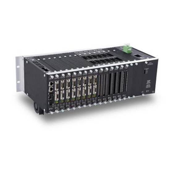
Power UMAC The Power UMAC is a modular rack-mounted configuration of the Power PMAC. It consists of a set of 3U-format (100mm x 160mm) boards in a Euro-Card rack. Along with the required Power PMAC CPU board, a customized set of interface boards can be added, communicating over a common backplane. -
Page 28: Compact Power Umac
Power PMAC User’s Manual Compact Power UMAC Starting in early 2014, the Power PMAC will also be available in the “Compact Power UMAC” configuration. This is similar to the standard Power UMAC, with 3U-format (100mm x 160mm) boards on a common backplane. However, the field wiring is distributed behind the backplane, as in the Compact PCI format (but there is no PCI interface). -
Page 29: Power Clipper
Power Brick AC 4-Axis Configuration Power Brick LV The Power Brick LV combines a Power PMAC controller with integrated motor amplifier circuits for 2-phase and 3-phase motors for 4 or 8 axes. It accepts a DC power input for the amplifiers of up to 60VDC. -
Page 30: Soft Power Pmac
Execute Sequenced Motion Programs The most obvious task of Power PMAC is executing sequences of motions given to it in a motion program written in the Power PMAC Script language. When told to execute a motion program, Power PMAC works through the program one move at a time, performing all the calculations up to that move command (including non-motion tasks) to prepare for actual execution of the move. -
Page 31: Process Feedback And Master Position Data
See Setting Up Commutation for more details. Close Motor Current Loops If Power PMAC is configured to perform digital current-loop closure for a motor (as part of the commutation algorithm), each commutation update it will automatically read the motor phase... -
Page 32: Provide Synchronous Data Gathering
PWM signals directly driving the amplifier power transistors. Provide Synchronous Data Gathering Every servo cycle (or every “n” servo cycles), Power PMAC can automatically log the values of up to 128 user-specified hardware and/or software registers into a data buffer for later analysis. -
Page 33: Key Hardware Components
CPU Section The core of the Power PMAC is the central processing unit (CPU), consisting of a microprocessor, active memory, and non-volatile memory. The following figure shows the block diagram of the Power PMAC CPU for the UMAC rack-mounted controller. Other configurations are similar. -
Page 34: Machine Interface Ics
Power PMAC User’s Manual Active Memory (RAM) The active memory in Power PMAC is DDR2 class RAM, typically with a capacity of 1 – 2 gigabytes (GB). This is error-correcting RAM to ensure the highest possible memory integrity. Non-Volatile Memory (Flash) The non-volatile memory provided with Power PMAC is solid-state flash memory. - Page 35 Clock, PLL 24-bit 6-bit DATA BUS ADDRESS BUS PMAC2-Style “DSPGATE1” Servo IC The DSPGATE1 IC is presently provided on the following Power PMAC products: ACC-24E2 UMAC PWM Axis-Interface Board ACC-24E2A UMAC Analog Axis-Interface Board ACC-24E2S UMAC Stepper Axis-Interface Board ...
- Page 36 The DSPGATE2 IC also has on-board software-configurable clock generation circuitry. It can generate the “servo” and “phase” clocks for the entire Power PMAC system (only one IC will do this; the others will accept these as inputs).
- Page 37 Power PMAC User’s Manual PMAC3-Style “DSPGATE3” Machine Interface IC The PMAC3-style “DSPGATE3” machine interface IC provides servo, MACRO, and I/O interfaces in a single IC. In different products, different parts of this interface are used. It appears to the processor as 512 memory-mapped 32-bit registers.
- Page 38 Finally, it has on-board software-configurable clock generation circuitry. It can generate the “servo” and “phase” clocks for the entire Power PMAC system (only one IC will do this; the others will accept these as inputs).
-
Page 39: Talking To Power Pmac
(IPv6), and Internet Control Message Protocol (ICMP). Power PMAC employs Internet Protocol Version 6 (IPv6). Each Power PMAC has an IP address. This is set at the factory to the default IP address of 192.168.0.200. The user can change this address. -
Page 40: Low-Level Terminal Communications
“terminal window”, but this can be changed to Telnet by the user. Power PMAC uses the FTP protocol for transfers of files to and from the Power PMAC, including the applications project files, and gathered-data files. Power PMAC’s “web server”... -
Page 41: Terminal Emulator Programs
Establishing First Communications The first step is to tell the program to establish communications with the Power PMAC at its IP address. In Windows Command Prompt, this is done by typing “telnet” followed by the IP... -
Page 42: Communicating With The Power Pmac Control Application
Communicating with the Power PMAC Control Application Once you have established communications with the Linux computer, you can communicate with the Power PMAC control application within the computer by starting the basic communications application gpascii. This application is in the opt/ppmac directory, so with the Linux prompt (#) at this directory (which it will be as you first establish communications), type “gpascii”... - Page 43 Power PMAC User’s Manual Starting Communications with the Power PMAC Control Application At this point, you are talking to the Power PMAC control application within the computer, and you can issue Power PMAC commands and view the responses. You might start by issuing several query commands to find out basic information about the Power PMAC.
-
Page 44: Establishing Communications With The Ide
Power PMAC. The IP address shown in the control must match that of your Power PMAC. You can enter a new IP address in this control if the address shown here does not match that of your Power PMAC. Note that the address you enter here simply specifies the IP address at which the IDE will attempt to communicate;... -
Page 45: Embedded Communications Control Window
If you want to view or change these settings after the start of execution of the IDE, select “Tools” on the top menu bar, then “Options” from the pull-down menu. When the Options control window appears, select Power PMAC. This will give you access to the same configuration choices as the start up control window, as shown below. -
Page 46: Changing The Power Pmac Ip Address
Changing the Power PMAC IP Address The IDE can also be used to change the IP address of the Power PMAC. To do this, select “Tools” on the top menu bar, then “Options” from the pull-down menu. When the Options control window appears, expand the “Power PMAC”... -
Page 47: Finding An Unknown Ip Address
Finding an Unknown IP Address If you do not know the IP address of your Power PMAC, it is of course impossible to ask for the address using Ethernet communications. If you find yourself in this situation, you have two methods for finding the address. -
Page 48: Power Pmac Commands
On-Line (Immediate) Commands Many of the commands given to Power PMAC are on-line commands; that is, they are executed immediately by Power PMAC, to cause some actions, change some variable value, or report some information back to the host. - Page 49 You can then simply type j/ to stop this same motor, as Motor 1 is still the addressed motor in the thread. However, when generating motor-specific on-line commands in software for Power PMAC, you are strongly advised to address the motor before each command to avoid possible intervening changes in the modally addressed motor.
-
Page 50: Buffered Program Commands
1. Buffered Program Commands As their name implies, Power PMAC Script buffered program commands are not acted on immediately, but held (buffered) for later execution. Sending a buffered program command to Talking to Power PMAC... -
Page 51: Power Pmac Processing Of Commands
Power PMAC User’s Manual Power PMAC merely causes the command to be loaded into the open program buffer; the command will not actually be executed until that program is run. Power PMAC has many Script program buffers – 1023 regular motion program buffers, 1 rotary... - Page 52 When the value of a variable or data structure element, or the definition of a pointer variable (I or M-variable), is queried, Power PMAC can either “echo” the query command as part of the response, or not. If the query command is echoed in the response, the response is of a form that could then be used as a command to set the value or definition.
- Page 53 “Properties”, “Control”, and “General”. Error Reporting If there is an error in the command, the Power PMAC will return an error message with error number and error type. For example: nonsensecommand stdin:3:1: error #20: ILLEGAL CMD: nonsensecommand motor[333].JogSpeed...
- Page 54 Power PMAC User’s Manual Reserved MOTOR NOT ACTIVE 46..49 Reserved MACRO COM TIMEOUT MACRO PORT NOT OPEN MACRO RING SELECTED NOT AVAILABLE OR PPMAC NOT SYNCH MASTER MACRO NOT AVAILABLE, NO MACRO ICs MACRO ASCII REQUEST EXCEEDED BUFFER SIZE MACRO ASCII COM TIMEOUT...
-
Page 55: Power Pmac System Configuration
General Configuration A Power PMAC system can report key aspects of its configuration to the user. Typically the best way to see this information is in the “CPU Information” window of the IDE’s Task Manager (selected from the “Tools” menu). A sample is shown here:... -
Page 56: Interface Ics Present
Power PMAC User’s Manual Interface ICs Present Power PMAC will report the interface ICs (“Gates”) of each type that it has found in the following status data structure elements: Sys.Gate1AutoDetect DSPGATE1 PMAC2-style Servo ICs Sys.Gate2AutoDetect DSPGATE2 PMAC2-style MACRO ICs ... -
Page 57: Change In Configuration
Power PMAC System Clock Source In a Power PMAC system, the system phase and servo clocks, which interrupt the processor and latch key input and output data for the servos, come from one (and only one) of the Servo ICs or MACRO ICs in the system. -
Page 58: Distribution Of Clock Signals
PSD = 0 PSD: Gaten[i].PhaseServoDir Power PMAC System Clock Generation Example Saved setup element Gaten[i].PhaseServoDir controls the “direction” of the clock signal for each of these DSPGATEn ICs. If the variable value is 0, the IC generates its own clock signals and outputs them. -
Page 59: Re-Initialization Clock Actions
UBUS backplane. Re-Initialization Clock Actions On re-initialization of a Power PMAC system with the $$$*** command, the CPU searches all possible locations of Servo ICs and MACRO ICs to see which are present. It selects one as the clock source based on the following priority:... -
Page 60: Changing The Clock Source From Default
1 when the IC is a source, so it can output the clock signals. The Software Reference Manual chapter Power PMAC I/O Address Offsets has a table of the x index values for all Gaten[i] IC values. The most commonly used are Cid[2] for Gate1[4] and Cid[4] for Gate2[0]. -
Page 61: Phase-Clock Software Tasks
Power PMAC User’s Manual Communication over MACRO ring (phase clock) Phase-Clock Software Tasks The software tasks that are driven by the phase clock signal include: Digital current loop closure Motor phase commutation Demuxing of muxed A/D converters ... -
Page 62: Real-Time Interrupt Software Tasks
*Can be delayed with non-zero value for Sys.CompMotor Real-Time Interrupt Software Tasks The “real-time interrupt” in Power PMAC is a software interrupt that occurs every (Sys.RtIntPeriod + 1) servo interrupts. At the end of the servo tasks for these cycles, the real- time interrupt software tasks are performed. -
Page 63: Background Tasks
Watchdog timer reset Each background cycle, Power PMAC repeats a loop of executing one scan of one active background Script PLC program, then one scan of all active background C PLC programs until all of the active background Script PLC programs have executed, followed by one pass of the background housekeeping and status update tasks. -
Page 64: Multi-Tasking Example
10.0 milliseconds, with a default of 1.0 millisecond. Multi-Tasking Example The following time-line drawing provides an example of how Power PMAC allocates time for different tasks. The top line shows one phase cycle, with the phase tasks highlighted in red at the beginning of the cycle, immediately following the interrupt. -
Page 65: Using The Ide To Set Phase And Servo Clock Frequencies
Once you have entered the settings you want, click on the “Accept” button on the right to load the appropriate settings into the Power PMAC. The following sections explain how to make these settings manually and directly, both for understanding and to permit other avenues for specifying these settings. - Page 66 Power PMAC User’s Manual In this description, n is 1 for a DSPGATE1 Servo IC, or 2 for a DSPGATE2 MACRO IC. The following figure shows the block diagram for the circuits that generate these clock signals, as well as the “hardware clock” signals in a PMAC2-style IC.
- Page 67 Power PMAC User’s Manual Gaten[i].PhaseClockDiv: Phase Clock Frequency Control From the internal “MaxPhase” clock signal, the phase clock signal is generated with a frequency divider circuit that is controlled by Gaten[i].PhaseClockDiv. The phase clock frequency is equal to the “MaxPhase” clock frequency divided by (Gaten[i].PhaseClockDiv + 1).
-
Page 68: Setting Phase And Servo Clock Frequencies In Pmac3-Style Ics
Power PMAC User’s Manual Setting Phase and Servo Clock Frequencies in PMAC3-Style ICs In a PMAC3-style “DSPGATE3” machine-interface IC, the internally generated phase and servo clock frequencies are determined by the setting of two saved setup elements for the IC: ... -
Page 69: Clock-Related Software Settings
Sys.PhaseOverServoPeriod: Ratio of Phase to Servo Period If a Power PMAC motor has been set up to close its servo loop under the phase interrupt by setting bit 3 (value 8) of Motor[x].PhaseCtrl to 1, it must compute a new desired position every software phase update with a “sub-interpolation”... -
Page 70: Setting The Phase And Servo Clock Period In The Cpu
Setting the Phase and Servo Clock Period in the CPU If there are no DSPGATEn ICs in the Power PMAC system to generate system phase and servo clocks to interrupt the processor, the processor can be set up to generate its own interrupt internally. -
Page 71: Diagnosing Issues With Clock Settings
Missing Clock Signals At power-up/reset, if the Power PMAC is expecting to receive hardware phase and servo clock signals (that is, the saved value of Sys.CpuTimerIntr is 0) but does not receive them, it will set global status bit Sys.NoClocks to 1. When this occurs, the processor continues to operate, but no motors may be enabled. - Page 72 The user can set the Sys.MinPhaseTime and Sys.MaxPhaseTime elements to 0.0 to “reset” them, and Power PMAC will restart its evaluation of the lowest and highest times, respectively, from this point. This is useful when a change in configuration is made.
- Page 73 The user can set the Sys.MinRtIntTime and Sys.MaxRtIntTime elements to 0.0 to “reset” them, and Power PMAC will restart its evaluation of the lowest and highest times, respectively, from this point. This is useful when a change in configuration is made.
- Page 74 Power PMAC User’s Manual The background cycle does not have a fixed period. After a background cycle’s tasks complete, the background execution thread “sleeps” for the time set by Sys.BgSleepTime (1.0 millisecond by default) before it will look to start the next cycle. This interval provides independent C applications with time to execute.
-
Page 75: Setting Up The Macro Ring
There are several hardware interfaces to the MACRO ring for Power PMAC configurations. With each interface, the Power PMAC can be configured as a master or a slave on the ring, although it is much more common to configure it as a master. -
Page 76: Acc-5Ep3 Macro Interface For Etherlite
Power PMAC User’s Manual ACC-5EP3 MACRO Interface for Etherlite The Power PMAC Etherlite network controller uses the ACC-5EP3 for the MACRO interface. This device can be configured with one or two PMAC3-style “DSPGATE3” MACRO ICs. Each IC supports up to 32 nodes of communication over the ring, in two banks, with a separate “master IC”... -
Page 77: Pmac3-Style Macro Ic
An IC used as a non-synchronizing master should have bit 4 set to 1 and bit 5 set to 0. If the IC is in the same Power PMAC system as the ring’s synchronizing master IC, it receives the ring- controlling phase clock signal directly, and does not need to use the receipt of the sync packet to stay synchronized. - Page 78 An IC used as a non-synchronizing master should have bit 12 set to 1 and bit 13 set to 0. If the IC is in the same Power PMAC system as the ring’s synchronizing master IC, it receives the ring- controlling phase clock signal directly, and does not need to use the receipt of the sync packet to stay synchronized.
-
Page 79: Setting The Ring Frequency
ICs over PMAC2-style ICs if both are present) as its source for the phase (and servo) clock signal it uses internally. The general topic of setting the clock frequencies for a Power PMAC system is covered in the Power PMAC System Configuration chapter of the User’s Manual. This section covers those aspects particular to systems with a MACRO ring interface. -
Page 80: Pmac3-Style Macro Ic
“phase lag” of the feedback loop, reducing or even eliminating the stability margins of the loop. If Power PMAC is closing the current loops of motors in “direct PWM” mode, as with Delta Tau’s Geo MACRO drives, the added ring delays can have a significant impact on the quality of the resulting performance. - Page 81 MACRO Loop Delays Without and With Phase Cycle Extension If Power PMAC is commanding drives over the MACRO ring in torque or velocity mode, as with most third-party MACRO drives, the fact that the ring is updated every phase-clock cycle, but new data is only used every servo cycle typically provides sufficient “oversampling”...
-
Page 82: Enabling Macro Nodes
MACRO IC Node Allocation Typical Mapping of MACRO Nodes to Motors While many different mappings between motors and MACRO nodes in a Power PMAC are possible, the standard mapping works in numerical order with the lowest-numbered motor mapped to the lowest-numbered servo node of the first MACRO IC, the next motor mapped to the next servo node of this IC, and so on until all 8 servo nodes of this IC (or bank of the IC) have been allocated. -
Page 83: Enabling Nodes In A Pmac2-Style Macro Ic
In the second part, bits 16 – 19, which form the second hex digit, specify the node number of the sync packet. In standard Power PMAC operation, this packet belongs to Node 15, so this hex digit is set to $F. -
Page 84: Enabling Nodes In A Pmac3-Style Macro Ic
In the second part, bits 24 – 27, which form the second hex digit, specify the node number of the sync packet. In standard Power PMAC operation, this packet belongs to Node 15, so this hex digit is set to $F. -
Page 85: Ring Check Function
Each MACRO node in an IC has 8 hardware data registers – 4 output registers and 4 input registers. In a master device on the MACRO ring (which the Power PMAC usually is), the output registers of a servo node are “command” registers, and the input registers are “feedback”... -
Page 86: Data Elements In A Pmac3-Style Macro Ic
Note All of these data elements are 24-bit values (found in the high 24 bits of Power PMAC’s 32-bit bus). For registers 1, 2, and 3 of a node, the real 16 bits of data are found in the high 16 bits of the 24-bit element. -
Page 87: Encoder Table Entry Source Address: Enctable[N].Penc
Power PMAC User’s Manual Encoder Table Entry Source Address: EncTable[n].pEnc The encoder table entry will read the input (feedback) register for the node as the source of its data. To specify this, EncTable[n].pEnc for the entry needs to be set to the address of this register. -
Page 88: Intermediate Processing: Enctable[N].Index1, Index2
Power PMAC User’s Manual With PMAC3-style ICs, the standard mapping for a 20-axis system would be: ECT Variable PMAC3 IC Source Address EncTable[1].pEnc Gate3[0].MacroInA[0][0].a EncTable[2].pEnc Gate3[0].MacroInA[1][0].a EncTable[3].pEnc Gate3[0].MacroInA[4][0].a EncTable[4].pEnc Gate3[0].MacroInA[5][0].a EncTable[5].pEnc Gate3[0].MacroInA[8][0].a EncTable[6].pEnc Gate3[0].MacroInA[9][0].a EncTable[7].pEnc Gate3[0].MacroInA[12][0].a EncTable[8].pEnc Gate3[0].MacroInA[13][0].a EncTable[9].pEnc Gate3[0].MacroInB[0][0].a EncTable[10].pEnc... -
Page 89: Change Limiting: Enctable[N].Index3, Maxdelta
If one or more higher-order bits are wrong when received by the Power PMAC, it could have significant effects on performance. The ECT permits you to implement a “maximum change” filter in an encoder table entry to mitigate the effects of such errors. -
Page 90: Setting Up Motor Addressing Elements
Power PMAC compute the exact numerical values. Setting Up Motor Addressing Elements When Power PMAC controls a motor over the MACRO ring, it reads its inputs from MACRO IC registers, and writes its outputs to MACRO ring registers. The actual hardware inputs and outputs occur at a slave node on the ring. -
Page 91: Position Feedback Address
Power PMAC User’s Manual If Power PMAC is not performing commutation or current-loop closure for the motor, the single command output from the servo loop will be written to this register. If Power PMAC is performing commutation for the motor, but not the digital current-loop closure (sinewave output mode), the first phase-current command (A) will be written to this register (0), and the second phase-current command (B) will be written to the next register (1) for the node. -
Page 92: Output Flag Addresses
When receiving flags over the MACRO ring for a motor, Motor[x].EncType should be set to 4 to tell Power PMAC of the expected format of the flags. With this setting, when Motor[x].pEncStatus is set to an address address (Gate2[i].Macro[j][3].a for a PMAC2-style IC, Gate3[i].MacroInA[j][3].a or Gate3[i].MacroInB[j][3].a for a PMAC3-style IC), Power... -
Page 93: Commutation Addresses
Power PMAC can perform “data shifting” operations on the value read from this register using Motor[x].PhaseEncRightShift and Motor[x].PhaseEncLeftShift. While PhaseEncRightShift can be used to shift out the low 8 bits of “garbage data” in the register, since Power PMAC only uses 11 bits of position data in a commutation cycle, this is seldom needed. - Page 94 ), or 16,384,000 register LSBs per commutation cycle. Motor[x].PhasePosSf should be set to 2048 / 16,384,000. It is usually best to enter this as an expression and let Power PMAC compute the exact resulting value. (In this case, the expression could be reduced to 1 / 8000).
-
Page 95: Setting Up A Motor As A Network Slave
Setting Up a Motor as a Network Slave It is possible to set up a Power PMAC motor to receive and act on cyclic commands from a network such as a MACRO ring. This is typically used to coordinate large numbers of motors on multiple Power PMAC systems together over a network. -
Page 96: Coordinating Power Pmac Motor Setup
A motor in the coordinating Power PMAC commanding a network-slave motor over the MACRO ring in another Power PMAC is set up just as if it were commanding a separate MACRO drive. A quick guide to the setup of the coordinating Power PMAC motor is given here. - Page 97 If the corresponding network-slave motor is expecting position commands, Motor[x].Ctrl for the coordinating Power PMAC motor should be set to Sys.PosCtrl so that no servo-loop closure is done by the Power PMAC motor, and position commands from the trajectory generator are directly output each servo cycle.
- Page 98 Power PMAC as well as the outer (position) servo loop. Motor[x].PhaseCtrl should be set to 4 to enable phase tasks in the coordinating Power PMAC interfacing through a MACRO IC. Motor[x].pAdc should be set to 0 to disable current-loop closure in the coordinating Power PMAC, since that task will be performed in the network-slave Power PMAC.
-
Page 99: Network-Slave Power Pmac Motor Setup
For the motor in the network-slave Power PMAC, the addressing saved setup elements are configured just as if the motor were operating independently. These elements will be set to the addresses of input and output registers in the Power PMAC itself. This permits the motor to be set Setting Up the MACRO Ring... - Page 100 Gaten[i].Chan[j].Status.a Processing of Position Feedback The position feedback for this motor that is to be sent back to the coordinating Power PMAC must be processed through the encoder conversion table just as if the motor were in independent operation, so the EncTable[n] entry should be set up in the same way as it would be for independent motor operation, reading the actual hardware input registers such as encoder counters and timers, and producing a single processed (“converted”) result.
- Page 101 If Motor[x].MotorMode is set to 1, 2, or 3, and the network-slave Power PMAC performs commutation and current-loop closure for the motor (this is the most common style of operation), then all of the commutation and current-loop parameters must be set on this Power PMAC, just as when the motor is operating independently.
-
Page 102: Setting Up Feedback And Master Position Sensors
SETTING UP FEEDBACK AND MASTER POSITION SENSORS Power PMAC systems can interface to a wide variety of position sensors for both feedback and “master” use. This section summarizes the basic hardware and software setup issues; more details can be found in the appropriate hardware reference manuals and the Power PMAC Software Reference Manual. -
Page 103: Hardware Setup
Power PMAC User’s Manual Hardware Setup This section describes the Power PMAC encoder hardware interface in general terms. Consult the Hardware Reference Manual for your particular configuration for details. Power PMAC’s encoder interface circuitry employs differential line receivers, but can accept single-ended encoders as well as differential encoders. - Page 104 It is also possible to use a separate supply for the encoders with non-isolated signals connected to Power PMAC. In this case, the return of the supply should be connected to the digital common GND on Power PMAC to give the signals a common reference. The +5V lines of separate supplies should not be tied together, as they could fight each other to control the exact voltage level.
-
Page 105: Hardware-Control Parameter Setup
With these “twisted pairs”, what noise does get in tends to cancel itself out in opposite halves of the twist. Hardware-Control Parameter Setup The Power PMAC ASICs are set up by default to accept quadrature feedback, but you may need to tweak some settings to optimize operation. Encoder Sample Clock Frequency After the front-end processing through the differential line receivers, the quadrature encoder inputs are sampled by digital logic in a PMAC2-style “DSPGATE1”... - Page 106 Power PMAC User’s Manual accessible with the Gaten[i].Chan[j].CountError status element. The problem can also be detected by capturing the count value each revolution on the index pulse and seeing whether the correct number of counts have elapsed. The SCLK frequency must be at least 4 times higher than the maximum encoder cycle (line) frequency input, regardless of the quadrature decoding method used (with the most common “times-4”...
-
Page 107: Using The Resulting Position Information
Power PMAC User’s Manual PMAC3-Style Interface IC SCLK Frequency Control In a PMAC3-style machine-interface IC, as on the UMAC Acc-24E3 axis-interface boards, the SCLK frequency is set by 4-bit saved setup element Gate3[i].EncClockDiv. This element, which can take a value from 0 to 15, indicates the number of times an internal 100 MHz clock frequency is divided by 2 to produce the SCLK signal. - Page 108 Power PMAC User’s Manual The following diagram shows a block diagram of the PMAC2-style “DSPGATE1” IC’s encoder circuitry, including the memory-mapped registers available to the processor. Servo Clock TimeBetweenCts Timers TimeSinceCts Decoder Counter ServoCapt EncCtrl Phase Clock PhaseCapt HOME PLIM...
- Page 109 Power PMAC User’s Manual Gaten[i].Chan[j].PhaseCapt. Most commonly, this element is used for the rotor angle feedback for commutation by setting Motor[x].pPhaseEnc to the address of this element. Servo Feedback or Master Position Each servo clock cycle, on the falling edge of the clock, the present value in the channel’s encoder counter is latched into the register represented by the element Gaten[i].Chan[j].ServoCapt.
-
Page 110: Setting Up Digital Hall Sensors
50% duty cycle, and nominally one-third cycle apart. This format is often called “120° spacing”. Power PMAC can also support “60° spacing” for the purpose of power-on commutation position, but its use is discouraged because of the increased difficulty in detecting signal failure. -
Page 111: Hardware Setup
Note the signals directly to the Power PMAC TTL inputs without isolation. If used for servo position and velocity feedback, the three hall sensors are connected to the A, B, and C “encoder”... -
Page 112: Using The Resulting Position Information
Power PMAC User’s Manual For a feedback sensor, the sensor’s direction sense must match the servo-loop output’s direction sense – a positive servo output must cause the counter to count in the positive direction – otherwise a dangerous runaway condition will occur when the servo loop is closed. -
Page 113: Setting Up Serial Encoders
FPGA. However, the principles of setup are the same in both cases. Because of the serial data protocol, the transfer of data from the encoder to the Power PMAC interface circuitry takes a significant amount of time. The data must be ready for the processor immediately after the falling edge of the phase and/or servo clock signals, which are the interrupts to the processor telling it to start those respective tasks. - Page 114 This section describes the setup elements for the serial encoder interface in general terms. Detailed information for each serial encoder protocol can be found in the Power PMAC software reference manual, and the manual for the appropriate hardware device.
- Page 115 SerialProtocol This section provides information about Gate3[i].SerialEncCtrl that is common to all protocols. For more detailed and protocol- specific information, refer to the Power PMAC Software Note Reference Manual and the appropriate hardware manual. The protocols presently supported in the ASIC, and their specifying codes in “pp”, are: ...
- Page 116 It is best to choose the edge that minimizes the delay between the triggering of the encoder and its use by the Power PMAC software. The software will use the received encoder value immediately after the falling edge of the phase clock for commutation feedback, and immediately after the falling edge of the servo clock for servo feedback.
- Page 117 Power PMAC User’s Manual The linear clock-frequency division component “mm” controls how an intermediate clock frequency is generated from the IC’s fixed 100 MHz clock frequency. The resulting serial- encoder clock frequency is then generated from this intermediate clock frequency by the exponential division component “nn”, described below.
- Page 118 This section provides information about Gate3[i].Chan[j].SerialEncCmd that is common to all protocols. For more detailed and protocol-specific information, refer to the Power PMAC Software Reference Manual and the Note appropriate hardware manual. The 16-bit component SerialEncCmdWord is used to define a command value sent to the serial encoder in a protocol-specific manner.
- Page 119 This section describes the setup elements for the serial encoder interface in general terms. Detailed information for each serial encoder protocol can be found in the Power PMAC software reference manual, and the manual for the appropriate hardware device.
- Page 120 It is best to choose the edge that minimizes the delay between the triggering of the encoder and its use by the Power PMAC software. The software will use the received encoder value immediately Setting Up Feedback and Master Position Sensors...
- Page 121 Power PMAC User’s Manual after the falling edge of the phase clock for commutation feedback, and immediately after the falling edge of the servo clock for servo feedback. If you are using the serial encoder data for commutation feedback, you must trigger using the phase clock in order to get new data every phase cycle.
- Page 122 This section provides information about Acc84E[i].Chan[j].SerialEncCmd that is common to all protocols. For more detailed and protocol-specific information, refer to the Power PMAC Software Reference Manual and the Note appropriate hardware manual.. The 8-bit component SerialEncCmdWord is used to define a command value sent to the serial encoder in a protocol-specific manner.
-
Page 123: Using The Resulting Position Information
Ongoing Commutation Phase Position For the commutation algorithm’s ongoing phase position, Power PMAC reads the entire 32-bit register specified by Motor[x].pPhasePos every phase cycle. In order to be able to handle... - Page 124 Power PMAC User’s Manual the 32-bit result, shifted if necessary. With most protocols, no shifting is necessary, but some will require a net “left shift” to achieve this result. PMAC3 ASIC-Based Interface To use serial encoder position from an ASIC-based interface for ongoing phase position, the following saved setup elements must be specified: ...
- Page 125 Power PMAC User’s Manual Motor[x].pAbsPhasePos = Gate3[i].Chan[j].SerialEncDataA.a Motor[x].AbsPhasePosFormat = $aabbccdd // Protocol-specific settings Motor[x].AbsPhasePosSf = 2048 / (LSBs per commutation cycle) Motor[x].AbsPhasePosOffset = (Difference between sensor zero and commutation zero) For the format variable, the LSB of the encoder data is typically found in bit 0 of the 32-bit register, and only enough bits to cover a single commutation cycle need to be used.
- Page 126 Many serial encoders can provide absolute position over the entire range of travel of the motor. If so, Power PMAC can execute an absolute power-on read of the encoder to establish the reference position, eliminating the need for a homing search move.
-
Page 127: Setting Up Analog Sinusoidal Encoders
(φ = PhaseError) Sinusoidal Encoder Common Signal Errors Power PMAC hardware and software have the capability of correcting for some or all of these errors. The accuracy requirements of a particular system can dictate which type of interface is used. -
Page 128: Sinusoidal Encoder Interfaces
Power PMAC User’s Manual Sinusoidal Encoder Interfaces Power PMAC provides three basic styles of interfaces for sinusoidal encoders. The first is based on the PMAC2-style “DSPGATE1” Servo IC, as used in the ACC-51E UMAC interpolator board. This requires the processor to compute the interpolated position from the hardware readings. -
Page 129: Hardware Setup
Interpolated hardware capture and compare based on corrected signals Hardware Setup This section describes the Power PMAC interpolator hardware interface in general terms. Consult the Hardware Reference Manual for your particular configuration for details. Interface Circuitry The interpolator analog hardware interfaces operate on a single 5V supply relative to the GND reference voltage. - Page 130 Power PMAC User’s Manual The following diagram shows the principle of the Power PMAC standard processing of the sinusoidal encoder signals. Sin+ Quad Counter Decode Sin- SCLK (MHz) Interpolated Position Servo Clock (kHz) Cos+ Fraction Arctangent Cos- Software (ECT) in PMAC2,...
-
Page 131: Hardware Control Parameter Setup
Power PMAC User’s Manual The use of differential signal pairs is very important in reducing the amount of noise at the receiver circuits. These signal pairs provide common-mode noise rejection, with the resulting voltage difference being much smaller than the disturbance to the individual signals. The signal pairs should be wired as twisted pairs, providing cancellation of received noise. - Page 132 Power PMAC User’s Manual ACC-51E PMAC2-Style Interface The UMAC ACC-51E interpolator uses the PMAC2-style DSPGATE1 ASIC to interface to the signals. With this accessory, the actual interpolation is always performed in software in the encoder conversion table. Encoder Sample Clock Frequency: Gate1[i].HardwareClockCtrl...
- Page 133 Power PMAC User’s Manual table (which is slower but supports corrections for voltage offsets, phase error, and magnitude mismatch. The saved setup elements for the DSPGATE3 IC described in this section require the proper “write protect key” be set in order to change their values.
- Page 134 Power PMAC User’s Manual Acquiring and processing the encoder data requires 25 cycles of the encoder ADC clock, which is 8 microseconds at the default ADC clock frequency. At the default phase clock frequency of 9 kHz, sampling fully a half phase cycle ahead yields a 55 microsecond delay, over 40 microseconds more than is needed.
- Page 135 Power PMAC User’s Manual element Gate3[i].Chan[j].AdcOffset[0] is added to the value measured from the “sine” signal in Gate3[i].Chan[j].AdcEnc[0], and the value in Gate3[i].Chan[j].AdcOffset[1] is added to the value measured from the “cosine” signal in Gate3[i].Chan[j].AdcEnc[1]. If the sub-count interpolation is to be done in the encoder conversion table using a software-based arctangent calculation there, these bias-compensation terms in the ASIC are not used.
- Page 136 Power PMAC User’s Manual Gate3[i].EncClockDiv specifies the frequency of the SCLK signal. The default value of 5 specifies a frequency of 3.125 MHz. This supports signal frequencies up to about 600 kHz, suitable for the majority of cases. Reducing the value of this element supports higher frequencies.
- Page 137 Power PMAC User’s Manual For standard operation with continuous auto-identification and auto-correction of encoder signal errors, Gate3[i].AdcEncStrobe should be set to $800000, which sets only the MSB to 1. In any mode of operation, this bit must be set to 1 to start the conversions synchronized to the phase clock cycle.
- Page 138 Power PMAC User’s Manual Gate3[i].AdcEncStrobe = Gate3[i].AdcEncStrobe & $FFFFF7 // Clear bit 3 for Chan[3] Hold Corrections: To freeze the present corrections to use in the interpolations, set the “Hold Corrections” bit for the channel to 1. To do this without changing any other settings, the following commands can be used: Gate3[i].AdcEncStrobe = Gate3[i].AdcEncStrobe | $800400...
- Page 139 Power PMAC User’s Manual each phase cycle. Note that while these values are not filtered, they are corrected using the most recently determined correction factors. To request the unfiltered corrected A/D converter values for a channel, set bit 0 of the “additional data request value”...
- Page 140 Power PMAC User’s Manual These velocity and acceleration values should not be used in integrated form for the outer-loop servo position feedback. They cannot be guaranteed to integrate properly into the actual position. The outer-loop position feedback should always come Note from one of the position values generated by the interpolator.
- Page 141 Power PMAC User’s Manual To request the velocity and acceleration values for a channel with n = 16 scaling, set bits 2 and 1 of the “additional data request value” for the channel to 1. To do this without changing any other settings, the following commands can be used: Gate3[i].AdcEncStrobe = Gate3[i].AdcEncStrobe | $844000 // Set bits 18 &...
- Page 142 Power PMAC User’s Manual Encoder Decode Control: Gate3[i].Chan[j].EncCtrl: The decoding of the digital quadrature encoder signal created in the interpolator hardware is determined by a channel-specific saved setup element for the IC – Gate3[i].Chan[j].EncCtrl. For interpolation of sinusoidal encoders, this must be set for “times-4” quadrature decode, which derives 4 counts per signal cycle. This requires a variable value of 3 or 7 (default).
-
Page 143: Using The Resulting Position Information
Ongoing Commutation Phase Position For the commutation algorithm’s ongoing phase position, Power PMAC reads the entire 32-bit register specified by Motor[x].pPhasePos every phase cycle. It then multiplies the value of the full register by Motor[x].PhasePosSf to rescale it into units of the standard commutation cycle... - Page 144 Power PMAC User’s Manual In the 24-bit ACC-51E, the LSB of the encoder counter is found in bit 8 on the 32-bit data bus, and so is equal to 256 LSBs of the 32-bit register. Each LSB of the counter is ¼ of an encoder line, because “times-4”...
- Page 145 Power PMAC User’s Manual The LSB of the SerialEncDataA register is 1/65,536 of an encoder line. The denominator of the expression for PhasePosSf should therefore be 65,536 times the number of encoder lines (signal cycles) per commutation cycle. Ongoing Servo Position To use the interpolated sinusoidal encoder position for ongoing servo position, the data must first be processed in the encoder conversion table.
- Page 146 Power PMAC User’s Manual PMAC3 Standard ASIC-Based Interface To use the hardware-interpolated sinusoidal encoder position from a PMAC3 standard ASIC- based interface for ongoing servo position, the following saved setup elements must be specified: EncTable[n].Type = 1 // Single-register read conversion ...
- Page 147 Power PMAC User’s Manual PMAC3 Auto-Correcting FPGA & ASIC-Based Interface With the Auto-Correcting Interpolator, there are several possibilities for using the resulting data in the servo loop: hardware-interpolated position, simulated serial-encoder position, direct velocity value, and direct acceleration value. Hardware-Interpolated Position: To use the full hardware- interpolated sinusoidal encoder...
- Page 148 Power PMAC User’s Manual EncTable[n].Type = 1 // Single-register read conversion EncTable[n].pEnc = Gate3[i].Chan[j].AdcEnc[2].a // Auxiliary ADC register EncTable[n].index1 = 8 // Shift left 8 bits EncTable[n].index2 = 8 // Shift right 8 bits EncTable[n].index4 = 1 // Single integration (velocity to position) ...
-
Page 149: Setting Up Resolvers
– do not permit the use of optical or magnetic encoders. In addition resolvers are absolute sensors, at least over one revolution of the motor. Power PMAC provides two basic interfaces for resolvers. The first is based on the PMAC3-style “DSPGATE3”... -
Page 150: Hardware Setup
WARNING operating commutation can cause a dangerous runaway condition. Hardware-Control Parameter Setup The Power PMAC hardware interface for resolvers is configurable in software with saved setup elements. Setting Up Feedback and Master Position Sensors... - Page 151 Power PMAC User’s Manual PMAC3 ASIC-Based Interface For the resolver interface using the PMAC3 ASIC, there are two setup elements in the IC, one multi-component element for all channels, and one element for each channel. The saved setup elements for the DSPGATE3 IC described in this section require the proper “write protect key”...
- Page 152 Power PMAC User’s Manual changed between its default value of 7 and 3, but for purposes of the resolver conversion, all that matters is the value of bit 2. For a feedback sensor, the sensor’s direction sense must match the servo-loop output’s direction sense – a positive servo output must cause the feedback to increment in the positive direction –...
-
Page 153: Using The Resulting Position Information
PMAC3 ASIC hardware, or in software in the ECT from the ACC-58E, ends up in the high 16 bits of a 32-bit register. Power PMAC reads the entire 32-bit register each phase cycle and scales the result to the 2048- part commutation cycle. (Note that this means that only the high 11 bits are really needed.) One... - Page 154 With the Power PMAC resolver interfaces, the same register is read for power-on phase position as for ongoing phase position, although the processing is done a little differently.
- Page 155 Power PMAC User’s Manual interface, where the interpolation has not been performed in the ASIC, and so must be performed in the software conversion. PMAC3 ASIC-Based Interface To use the hardware-converted resolver position from a PMAC3 ASIC-based interface for ongoing servo position, the following saved setup elements must be specified: ...
- Page 156 Power PMAC User’s Manual PMAC3 ASIC-Based Interface To use (a single) resolver position from a PMAC3-style ASIC-based interface for power-on servo position, the following saved setup elements must be specified: Motor[x].pAbsPos = Gate3[i].Chan[j].AtanSumOfSqr.a Motor[x].AbsPosFormat = $00001010 // Use high 16 bits of 32-bit register ...
-
Page 157: Setting Up Mldts
Start Stop Since Power PMAC uses the first rising signal edge returned after the falling edge of the output pulse to latch the timer, the key setup issue in this format is to make sure that the output pulse width is large enough so that the falling edge of the output pulse occurs after the rising edge of the return line’s start pulse (see “PFM Pulse Width”, below). -
Page 158: Hardware Setup
Power PMAC User’s Manual In the DPM format, there is only one long pulse returned from the MLDT. DPM Signal Format Pulse Out Return Start Stop The rising edge of the return pulse in the DPM format is the equivalent of the rising edge of the start pulse in the RPM format. - Page 159 Power PMAC User’s Manual PFM Format Select: Gate3[i].Chan[j].OutputMode The Phase D output signal for a channel used for the MLDT interface must be configured for PFM output rather than PWM output. The signal format is determined by bit 3 (value 8) of saved setup element Gate3[i].Chan[j].OutputMode.
- Page 160 Power PMAC User’s Manual servo update frequency for the motor, so each servo cycle uses new data. This may require lowering the servo update frequency for the motor. The PFM clock frequency, which sets the finest interval to which the pulse output timing can be controlled, is determined by the value of multi-channel saved setup element Gate1[i].HardwareClockCtrl.
-
Page 161: Using The Resulting Position Information
MLDT to the same channel’s feedback on Power PMAC. In this mode, it is the pulse timer that is used as a position measurement for feedback, Note not the pulse counter that is used with encoders. - Page 162 Power PMAC User’s Manual EncTable[n].Type = 1 // Single-register read EncTable[n].pEnc = Gate1[i].Chan[j].TimeBetweenCts.a EncTable[n].index1 = 8 // Shift left 8 bits to restore position EncTable[n].index2 = 8 // Shift right to eliminate lower 8 bits ...
-
Page 163: Setting Up Parallel Data Position Inputs
Only enough bits need to be connected so that the resulting numerical value cannot cover more than half of its cycle between consecutive servo cycles. If this is the case, Power PMAC can handle the rollover properly and extend the position data indefinitely. -
Page 164: Using The Resulting Position Information
Power PMAC User’s Manual The values of GateIo[i].Init.DataReg128[j], which control the numeric form expected for the specified data register (j = 0 to 5), should be set to $00 for the typical numeric binary, or to $FF for Gray code. - Page 165 Power PMAC User’s Manual noticeable effect on commutation performance. If necessary, this time delay can be compensated for with Motor[x].AdvGain. To use this processed data for ongoing commutation feedback, set Motor[x].pPhaseEnc to EncTable[n].PrevEnc.a, where n is the index of the ECT entry that is processing the feedback.
-
Page 166: Setting Up Analog Data Position Inputs
Note Signal Format The analog-input accessories for the Power PMAC accept a voltage input that is intended to be proportional to the quantity being measured. (The ACC-59E3 can also be configured to accept 4 – 20 mA current inputs, but that is seldom used for feedback data.) All of these accessories have differential analog inputs, measuring the voltage difference between ADCn+ and ADCn- input lines. -
Page 167: Hardware Setup
Power PMAC User’s Manual If the software convert code specifies bipolar conversion, then the range of input voltage difference (V[ADCn+] – V[ADCn-]) is -10V to +10V, corresponding to converted values of - 2048 to +2,047. ACC-59E3 On the ACC-59E3, the range of input voltage difference (V[ADCn+] – V[ADCn-]) is -10V to +10V, corresponding to converted values of -32,768 to +32,767. -
Page 168: Hardware Control Parameter Setup
To configure the ring cycle, the saved setup elements AdcDemux.Address[i] must be set to the address offset of the card in Power PMAC’s I/O space (e.g. to $A00000 for Acc36E[0] or Acc59E[0]). If every entry in the ring cycle is for the same card, each of these elements will be set to the same value. - Page 169 Finally, AdcDemux.Enable must be set to specify the number of slots in the ring cycle. Setting it to a value of 8 will cause Power PMAC to use the values of AdcDemux.Address[i] and AdcDemux.ConvertCode[i] for i = 0 to 7.
- Page 170 Power PMAC User’s Manual To enable the use of these control bits, saved direction-control element Acc59E3[i].GpioDir[0] must be set to $FFFFFFFF – not the default – so that all 32 of the IC’s 32 digital I/O lines are configured as outputs, and the saved polarity-control element Acc59E3[i].GpioPol[0] should be left at its default value of $00000000.)
-
Page 171: Using The Resulting Position Information
Power PMAC User’s Manual Using the Resulting Position Information The analog data can be used for either ongoing servo position feedback or master data, and if absolute, for power servo reference position. (Because analog position data has a very limited range, it is very rarely used for the cyclic position feedback for phase commutation.) - Page 172 Power PMAC User’s Manual Motor[x].pEnc = EncTable[n].a // Use result for position-loop feedback Motor[x].pEnc2 = EncTable[n].a // Use result for velocity-loop feedback If scale factors Motor[x].PosSf and Motor[x].Pos2Sf are set to the default values of 1.0, the motor units will be LSBs of the ADC.
- Page 173 Power PMAC User’s Manual Input IC Channel Channel Register Input IC Channel Channel Register Index j Index k Index j Index k ADC1 ADC9 ADC2 ADC10 ADC3 ADC11 ADC4 ADC12 ADC5 ADC13 ADC6 ADC14 ADC7 ADC15 ADC8 ADC16 The key elements for the ECT entry to process this value and for the motor to use the processed result are: ...
- Page 174 Power PMAC User’s Manual The key elements for the ECT entry to process this value and for the motor to use the processed result are: EncTable[n].type = 1 // Single register read EncTable[n].pEnc = PowerBrick[i].Chan[j].AdcAmp[2].a // ADC register address ...
- Page 175 Power PMAC User’s Manual Power-On Servo Position If the analog position data from one of these accessories is absolute over the entire range of travel for the motor, it can be used for power-on absolute servo position, eliminating the need for a homing search move.
- Page 176 Power PMAC User’s Manual Motor[x].AbsPosSf = (Motor units per LSB) // Must match ongoing pos resolution Motor[x].HomeOffset = (Difference between sensor zero and motor zero) Power Clipper Optional ADCs To use analog position data from the analog option of a Power Clipper for absolute power-on servo position, the following saved setup elements must be specified: ...
-
Page 177: Setting Up The Encoder Conversion Table
However, Power PMAC has an intermediate step using a software structure called the “Encoder Conversion Table” (ECT) to pre-process the information in the latched registers. This table tells Power PMAC what registers to process, and how to process them; it also holds the intermediate processed data. -
Page 178: Conversion Table Execution
Power PMAC User’s Manual Conversion Table Execution The conversion table executes automatically at the beginning of each servo cycle, immediately after the servo interrupt. The entire active part of the table executes before any servo loops execute that cycle. Each entry in the table is executed every servo interrupt, even if the result is used less often (as when a motor’s own servo cycle is extended with Motor[x].Stime) or not at... -
Page 179: Conversion Method Overview
This configuration window can be found under the “Delta Tau” menu bar item, then selecting “Configure” from the pull-down menu, followed by “Encoder Conversion Table”. -
Page 180: Scaling Of Entry Results
Power PMAC User’s Manual IDE Encoder Conversion Table Setup Window Scaling of Entry Results Each entry has a user-set floating-point output scale factor term EncTable[n].ScaleFactor that multiplies the internal integer result value and converts it to floating-point format. This means that the user can make the units of the result value anything he likes. -
Page 181: Using Conversion Table Results
The final result for each ECT entry every servo cycle is actually stored in the data structure element EncTable[n].DeltaPos. However, the motor addressing elements just described should not be given the address of this register directly, as Power PMAC automatically adds in the offset from the starting address of the entry to the DeltaPos element. -
Page 182: Default Conversion Table Setup
It starts assigning these entries with EncTable[1]. After all of the real entries it creates, all higher-numbered entries are set to the Type 0 “end of table” method so the Power PMAC does not waste time performing unneeded conversions. For example, if two 4-channel ICs are found, EncTable[1] through EncTable[8] are set up to use these. -
Page 183: Type 1: Single-Register Read
Power PMAC User’s Manual properly. The first entry encountered with Type 0 does nothing except indicate end of table; the values of other setup elements in the entry do not matter. If global setup element Sys.FirstEnc, which specifies the first entry to be processed, is set to a non-zero value, it does not matter if any entries with an index less than its value are Type 0. - Page 184 MSB of actual data in the source register to end up in the highest bit of the intermediate result register. This must occur if Power PMAC is to handle rollover of the source data value properly. For example, if the source register has 20 bits of real data starting at bit 8 (so in bits 8 – 27 of the 32-bit register), index2 should be set to 8 to eliminate the original bits 0 –...
- Page 185 “mantissa” of the “integral” gain term, and index4 serves as the “exponent” of the “integral” gain term. All are 8-bit unsigned integer values, with a range of 0 to 255. Filter Execution The following equations are executed by a tracking filter in a Power PMAC encoder conversion table (ECT) entry each servo cycle k: ...
- Page 186 Power PMAC User’s Manual where the digital gain terms K (digital integral gain) and K (digital proportional gain), expressed in terms of entry parameters, are: index Re-arranging these equations and converting to digital (z) transform form, we get: ...
- Page 187 Power PMAC User’s Manual From this, we can compute the overall transfer function of the filter: ...
- Page 188 Power PMAC User’s Manual 2. Compute the filter’s natural frequency ω = 2 * π * f 3. Select a damping ratio ς for the filter (usually = 0.7). 4. Compute the filter’s sample time T in seconds. This is the servo update period, and can be calculated as Sys.ServoPeriod / 1000.
-
Page 189: Type 2: Double-Register Read
= 1 / 2 = 1/4096. It is usually best to enter the value for ScaleFactor as an expression and let Power PMAC compute the exact resulting value. Type 2: Double-Register Read The Type 2 method reads two registers to assemble a 32-bit value before further processing. It can use up to 24 bits from the first register and up to 8 bits from the second register. - Page 190 Power PMAC User’s Manual DSPGATE2 IC, or the low 24 bits from a serial encoder through an ACC-84E board. In these cases, the setting is like: EncTable[n].pEnc = Gate2[i].LowIoData.a EncTable[n].pEnc = Acc84E[i].SerialEncDataA.a EncTable[n].pEnc1 is set to the address of the second source register. It takes data from bits 8 –...
-
Page 191: Type 3: Software 1/T Encoder Extension
= 1 / 2 = 1/16. It is usually best to enter the value for ScaleFactor as an expression and let Power PMAC compute the exact resulting value. Type 3: Software 1/T Encoder Extension The Type 3 method reads several registers in the channel of a PMAC2-style IC to process quadrature encoder data and estimate sub-count position data using timer registers in the IC channel. -
Page 192: Type 4: Software Arctangent Sinusoidal Encoder Extension
Power PMAC User’s Manual The PMAC3-style DSPGATE3 IC performs this timer-based extension in hardware, so this software extension method should not be used with the PMAC3-style IC. Instead, a Type 1 single- register read of the IC hardware channel’s ServoCapt register Note should be used. - Page 193 Power PMAC User’s Manual CosMag SinMag CosOffset 90° SinOffset θ φ (φ = PhaseError) Sinusoidal Encoder Common Signal Errors When the data comes from a PMAC2-style IC, 10 bits of sub-count fractional data are estimated, for a resulting resolution of 1/1024 of a quadrature count, or 1/4096 of an encoder line. When the data comes from a PMAC3-style IC, 14 bits of sub-count fractional data are estimated, for a resulting resolution of 1/16,384 of a quadrature count, or 1/65,536 of an encoder line.
- Page 194 Power PMAC User’s Manual proper combination of the whole-count and fractional-count data. If index3 is set to 0 at the start of execution of a cycle of the table entry, it will read the control value from the IC and copy this value into index3 for use in subsequent servo cycles.
- Page 195 1/65,536. It is usually best to enter the value for ScaleFactor as an expression and let Power PMAC compute the exact resulting value.
-
Page 196: Type 5: Four-Byte Read
Power PMAC User’s Manual Type 5: Four-Byte Read The Type 5 method reads four bytes in four separate registers to assemble a 32-bit value before further processing. It is mainly intended for data read through the “IOGATE” IC on modules such as the ACC-14E. -
Page 197: Type 6: Resolver Arctangent Direct Conversion
= 1 / 2 = 1/256. It is usually best to enter the value for ScaleFactor as an expression and let Power PMAC compute the exact resulting value. Type 6: Resolver Arctangent Direct Conversion The Type 6 method reads several registers of a device like an ACC-58E resolver-to-digital (R/D) converter board to calculate the angular position of a resolver. -
Page 198: Type 7: Extended Hardware Arctangent Interpolation
Power PMAC User’s Manual Offset Compensation Terms: SinBias and CosBias In general, there will be offsets in the ADC readings of the “sine” (Adc[0]) and “cosine” (Adc[1]) values that can limit the accuracy of the position value calculated with the arctangent function. -
Page 199: Types 8 And 9: Addition And Subtraction
1/16,384. For those who wish the result to be scaled in units of encoder lines, this should be set to 1/65,536. It is usually best to enter the value for ScaleFactor as an expression and let Power PMAC compute the exact resulting value. Types 8 and 9: Addition and Subtraction The Type 8 and 9 methods permit the addition and subtraction, respectively, of numerical values. -
Page 200: Type 10: Triggered Time Base
Power PMAC User’s Manual EncTable[n].pEnc1 is set to the address of the second source register. It reads the entire 32-bit value at this register, treating it as a signed integer. In most cases, this register will be the PrevEnc element of an earlier (lower-numbered) entry in the conversion table. In this case the setting is like: EncTable[n].pEnc1 = EncTable[l].PrevEnc.a... -
Page 201: Type 11: Floating-Point Register Read
Format of the Source Register: index6 If index6 is set to the default value of 0, Power PMAC will interpret the source value as a single- precision (32-bit) floating-point value. If index6 is set to 1, Power PMAC will interpret the source value as a double-precision (64-bit) floating-point value. - Page 202 ScaleFactor to 1/256. For direct microstepping, ScaleFactor is commonly set to 1/65,536. It is usually best to enter the value for ScaleFactor as an expression and let Power PMAC compute the exact resulting value. Setting Up the Encoder Conversion Table...
-
Page 203: Type 12: Single Register Read With Error Check
EncTable[n].pEnc1 is set to the address of the register containing error, alarm, and/or status bits for the position source. Power PMAC will read the full 32-bit register at this address, then only use the specified bits to determine whether or not there is an error. - Page 204 Power PMAC User’s Manual DSPGATE3-Based Interfaces Protocol Gate3[i] Element Bits Mask Word index6 value SerialEncDataB Status bits 31:20* $FFF00000* SerialEncDataB Error bit 31 $80000000 EnDat 2.1 SerialEncDataB Error bits 31:29 $E0000000 Hiperface (not for cyclic read) Yaskawa I (not for cyclic read)
- Page 205 MSB of actual data in the source register to end up in the highest bit of the intermediate result register. This must occur if Power PMAC is to handle rollover of the source data value properly. For more information and examples for these elements, refer to the description of Type 1, above.
-
Page 206: Basic Motor Setup
Power PMAC User’s Manual BASIC MOTOR SETUP Power PMAC has many modes for controlling motors. A major part of the initial setup of a Power PMAC is the hardware and software configuration to specify a specific mode of operation. The commonly used modes of operation are: ... -
Page 207: Ide Interactive Setup
Power PMAC User’s Manual IDE Interactive Setup Power PMAC’s Integrated Development Environment (IDE) software for the PC has interactive menus that walk the user through much of this setup. Most users will be able to use these menus to accomplish their motor setup, reducing or eliminating the need to use the material in this chapter. - Page 208 Power PMAC User’s Manual Beginning Motor Setup Use PMAC to Basic commutate and/or close Commutation current loop? Setup Single Output Use PMAC to close Setup current loop? Analog Sine-Wave Direct PWM Output? Output Output Setup Setup Pulse and Analog Current Loop...
-
Page 209: Initial Setup Parameters
0 (value 1) or bit 2 (value 4) must be set to 1. If bit 2 is set to 1 (typically Motor[x].PhaseCtrl = 4), Power PMAC will perform commutation tasks for the motor with any phase input and output values accessed in separate registers for each phase. -
Page 210: Motor Address Setup Parameters
Each Power PMAC motor has several “address” setup elements that tell the motor what registers to use for its inputs and outputs. Each of these variables contains the Power PMAC address of the register for the particular function. This provides a “mapping” between the motor calculation registers and the different types of servo I/O registers (encoders, D/A converters, flags, etc.) used... -
Page 211: Motor Vs. Load Feedback
“inside” the servo loops closed with its feedback, making it more difficult to achieve stable control. Power PMAC makes it easy to utilize dual motor/load feedback to get the advantages of both sensor placements. It closes an outer position loop with its choice of feedback sensor, and an inner velocity loop with a separate choice of feedback sensor. -
Page 212: Outer (Position) Loop Feedback: Motor[X].Penc, Possf
Power PMAC User’s Manual Outer (Position) Loop Feedback: Motor[x].pEnc, PosSf Motor[x].pEnc specifies the address of the register Power PMAC reads for the ongoing outer- loop feedback for the motor. The outer loop is virtually always the position loop for the motor. -
Page 213: Changing Feedback On The Fly
Motor[x].EncType specifies the type of the primary feedback used for the motor. On re- initialization of the Power PMAC it is set automatically based on the interface hardware found by the processor to the most common type of sensor used with that interface. The user can change the value subsequently. -
Page 214: Encoder Status Address: Motor[X].Pencstatus
Motor[x].EncType. Limit Flag Address: Motor[x].pLimits, LimitBits Motor[x].pLimits specifies the address of the register Power PMAC reads for the status of the hardware overtravel limit flag inputs for the motor. Almost always, this is the status register for the channel of an ASIC used for servo interface, so it will take the form of Gaten[i].Chan[j].Status.a, or if the MACRO ring is used for the motor, Gate2[i].Macro[k][3]... -
Page 215: Amplifier Fault Flag Address: Motor[X].Pampfault, Ampfaultbit
Motor[x].EncType. Power PMAC always considers a “0” in the limit status bit to mean the motor is not into the limit, and a “1” to mean that the limit switch has been reached. With standard Delta Tau interface hardware, a “0”... -
Page 216: Absolute Power-On Position Address: Motor[X].Pabspos
Motor[x].pAbsPos should be set to 0. (If Power PMAC is performing the phase commutation for such a motor, the similar element Motor[x].pAbsPhasePos can be set to read this sensor for absolute position within one commutation cycle.) -
Page 217: Is Power Pmac Commutating Or Closing The Current Loop For This Motor
The Power PMAC setup for both types of control is the same with the exception of the servo loop tuning. With a velocity-command output, the velocity loop is closed in the drive, and the velocity- feedback gains in the Power PMAC can be set to 0.0 (provided the drive’s velocity loop is well... - Page 218 Power PMAC User’s Manual This diagram shows the output circuitry for a channel of the PMAC2-style DSPGATE1 IC. Output Mode Control Bits PwmAtop Pulse Width PwmAbot Modulator Phase A Command Value DacClk DAC Shift DacAdata Register DAC Clock & Strobe Control...
- Page 219 Power PMAC User’s Manual The following diagram shows the output circuitry for a channel of the PMAC3-style DSPGATE3 IC. It has four phases (A, B, C, and D), rather than the three of the DSPGATE1 IC. Output Mode Control Bits...
-
Page 220: Asic Programmable Signal Setup
The default value of $7FFFC0, with 17 bits set to 1, is suitable for use with the 18-bit DACs used by Delta Tau with these ICs. In general, for an n-bit DAC, n-1 bits of the strobe word are set to 1. - Page 221 IC and channel are inverted or not. The default value of 0 (non-inverted) is suitable for use with any of the Delta Tau analog outputs. Inverting the bits of the serial data stream has the effect of negating the DAC voltage.
-
Page 222: Setting Up Power Pmac For Pulse-And-Direction Control
“stepper-replacement” servo drives that require this format. Power PMAC can command these drives either in open-loop fashion, in which case it internally routes the pulse train into its own encoder counters to create a pseudo- closed loop, or in closed-loop fashion, in which case an external feedback device is wired to the Power PMAC to create a true feedback loop. -
Page 223: Hardware Setup
Power PMAC User’s Manual Hardware Setup PMAC2-style and PMAC3-style ICs have pulse-and-direction outputs for each channel on the IC. In most configurations of interface and breakout hardware, these signals are accessible as RS- 422-level differential line-driver output pairs. These signals are driven by the value in a register for the channel, with the pulse frequency proportional to the value in this register. -
Page 224: Power Pmac Parameter Setup
Power PMAC User’s Manual Power PMAC Parameter Setup Hardware Setup for PMAC2-Style ICs With the PMAC2-style “DSPGATE1” ICs, many of the Gate1[i] setup elements for the PFM outputs are shared with other functions. PFM Clock Frequency: Gate1[i].HardwareClockCtrl Gate1[i].HardwareClockCtrl determines the frequency of addition of the command value into the accumulator by setting the frequency of the internal PFM clock signal. - Page 225 Power PMAC User’s Manual above table shows the value of the I-variable for each possible frequency of the PFMCLCK, assuming the SCLK frequency is set equal to the PFMCLK frequency, and the DACCLK and ADCCLK frequencies are left at their default settings.
- Page 226 Power PMAC User’s Manual PFM Clock Frequency: Gate3[i].PfmClockDiv Gate3[i].PfmClockDiv determines the frequency of addition of the command value into the accumulator by setting the frequency of the internal PFM clock signal. One addition is performed during each PFM clock cycle, so the addition frequency is equal to the PFM clock frequency. The pulse frequency for a given command value is directly proportional to this addition frequency.
- Page 227 Power PMAC User’s Manual Output Inversion Control: Gate3[i].Chan[j].OutputPol Gate3[i].Chan[j].OutputPol controls whether the pulse signals are inverted or not. A value of 0 or 1 means the PFM pulse is high-true; a value of 2 or 3 means that it is low true.
- Page 228 (ECT) before it can actually be used by the Power PMAC motor for feedback. Most people use the setup window in the IDE to configure the entry, as it calculates many of the needed values for you and presents the possible choices to you.
- Page 229 Power PMAC User’s Manual When using a PMAC2-style IC, to get the count value without 1/T sub-count extension, you would select “Type 1” conversion (single-register read). This method has the advantage of not being susceptible to dithering due to sub-count feedback values. In the IDE menu, you just need to specify that the source register is the PhaseCapt register for the channel, to use 24 bits starting at bit 8, with one output unit per count.
-
Page 230: Setting Up Power Pmac For Position-Output Control
Power PMAC Parameter Setup Since much more of the work is being done external to Power PMAC in this mode, there are fewer parameters to set up. However, several parameters must be set correctly in order for this mode to operate correctly. - Page 231 Refer to instructions for the particular network for details. Position Feedback Address: Motor[x].pEnc Because Power PMAC is not closing the position loop in this mode, it is not necessary to set Motor[x].pEnc to the address of a register containing the actual position. However, if the Power PMAC is not reading actual position information through a register specified by Motor[x].pEnc,...
-
Page 232: Setting Up Power Pmac-Based Commutation And/Or Current Loop
Beginning Setup of Commutation If Power PMAC is to perform the commutation of a motor, it must do more than simply close the position/velocity-loop servo for the motor. Several parameters must be set up correctly to configure the commutation. -
Page 233: Commutation Enable: Motor[X].Phasectrl
0. This data structure element has several independent control bits. “Unpacked” Commutation I/O If bit 2 (value 4) of Motor[x].PhaseCtrl is set to 1, Power PMAC will perform commutation for the motor, with the command output for each phase written to separate consecutively registers, and the phase current feedback (if used) read from separate consecutively addressed registers. -
Page 234: Commutation Position Feedback Source: Motor[X].Pphaseenc
(0 to 15). Power PMAC reads the specified 32-bit register without masking out any bits. If the position data in the register can roll over, the most significant bit of the data must be in the highest bit (bit 31) of the register. -
Page 235: Commutation Position Source Processing: Motor[X].Phaseencrightshift, Motor[X].Phaseencleftshift
Commutation Position Source Processing: Motor[x].PhaseEncRightShift, Motor[x].PhaseEncLeftShift In most applications, Power PMAC simply reads the 32-bit register whose address is specified by Motor[x].pPhaseEnc and uses the 32-bit value to calculate the commutation phase angle. However, there are a few cases where this may not be sufficient. If there is any possibility that the value in this register could “roll over”... -
Page 236: Current Loop In Power Pmac Or Not: Motor[X].Padc
5000 LSBs comm It is often easier to let Power PMAC do the math for you, so the following command could be used to set this element for Motor 1: Motor[1].PhasePosSf = 2048 / 5000 / 256 In another example, a linear motor has a 64-millimeter commutation-cycle length, using a sinusoidal encoder of 20-micron pitch interpolated through a PMAC3-style ASIC. - Page 237 Motor[x].pAdc controls which mode of operation is used. If it is set to 0, Power PMAC will not close the current loops for the motor. Further setup for this mode is covered in the next section, “Setting Up for Sine-Wave Output Control”.
-
Page 238: Setting Up For Sine-Wave Output Control
Power PMAC User’s Manual Setting Up for Sine-Wave Output Control This section explains how to set up the commutation scheme if Power PMAC is performing the commutation for a motor, but not the digital current loop. In this mode, Power PMAC outputs two phase current commands to the amplifier, usually as analog voltages through digital-to- analog converters (DACs). - Page 239 PMAC3-style “DSPGATE3” ICs are used on ACC-24E3 axis interface boards for the UMAC rack-mounted control systems and in the Power PMAC Brick Controller. These can be ordered with analog-amplifier interface boards with one or two DACs per servo channel. The configuration with two DACs per servo channel must be ordered to perform sine-wave output commutation.
-
Page 240: Motor Software Setup
Motor[x].pDac instructs Power PMAC where to place its output commands for the motor by specifying the address of the first register. In sinewave output mode, Power PMAC will write to this register and the next higher addressed register. Almost always in this mode, the registers specified are the A and B-phase DAC output registers in a Servo IC, or the matching registers in a MACRO IC that will send the output information over the ring. - Page 241 Motor[x].PhaseOffset controls the angular relationship between the phases of a multiphase motor. Power PMAC splits the commutation cycle into 2048 parts. For a 3-phase motor, the angle from Phase A to Phase B is ±1/3 of a cycle, so this variable is set to ±683. For a 2-phase motor, the angle from Phase A to Phase B is ±1/4 of a cycle, so this variable is set to ±512.
- Page 242 With sinewave-output commutation, Power PMAC is not measuring the actual current in the motor and amplifier, so it uses the commanded current values in its calculations Almost always it is the continuous current rating of the motor that is used for this limit.
- Page 243 Power PMAC User’s Manual For details on how to calculate the appropriate value for I2tSet, refer to the Current Limits section of the User’s Manual chapter Making Your Power PMAC Application Safe. Integrated Current Limit: Motor[x].I2tTrip Motor[x].I2tTrip sets the permitted limit of the time-integrated current over the continuous current value.
-
Page 244: Setting Up For Direct Pwm Control
Power PMAC User’s Manual Setting Up For Direct PWM Control In direct-PWM control mode, Power PMAC is performing both the commutation and current- loop algorithms for the motor. The amplifier performs only the power conversion task, and is typically called a “power-block” amplifier. In this mode Power PMAC outputs PWM voltage commands for each phase of the motor. - Page 245 Bottom Signal PWM Signal Generation in PMAC ASICs By directly commanding the on-off states of the power transistors in this manner, Power PMAC minimizes the calculation and transport delays in the feedback loops. This permits the use of higher gains, which in turn permit greater stiffness, acceleration, and disturbance rejection. Also, digital techniques permit the use of mathematical transformations of the current-loop data, turning measured AC quantities into DC quantities for loop closure.
- Page 246 On Power PMAC, saved setup element Motor[x].IdCmd determines the magnitude of the direct current.
-
Page 247: Hardware Setup
Power PMAC Direct PWM Commutation with Digital Current Loop Hardware Setup For Power PMAC to operate a motor in the direct PWM output mode, three PWM top-and- bottom signal pairs, and two current measurements through ADCs, are required for the motor. - Page 248 “MaxPhase” clock to twice the PWM frequency for the channels on that IC. The MaxPhase clock is the highest frequency at which Power PMAC’s phase update tasks, which include phase commutation and digital current loop closure, can operate. Note that any change to this IC’s Gate1[i].PwmPeriod automatically changes the Phase and Servo clock...
- Page 249 (4 – n) bits of the strobe word should be set to 0 to delay the start of the strobe (if there are no delays in the data response). The ADCs in Delta Tau’s “Geo” family of direct-PWM drives have one bit of header data, and so require this last bit to be set.
- Page 250 PMAC3-style “DSPGATE3” ICs are used on ACC-24E3 axis interface boards for the UMAC rack-mounted control systems. These can be ordered with digital-amplifier “mezzanine” boards with three or four PWM phases per servo channel. They are also used in the Power PMAC “Brick” integrated controller/amplifier.
-
Page 251: Motor Software Setup
“null” header bits. This should be set according to the instructions of the particular amplifier(s) being driven. The default value of 2 is suitable for most Delta Tau amplifiers, whose ADCs have one true header bit and one clock cycle delay. Motor Software Setup Command Output Address: Motor[x].pDac... - Page 252 Register 0 for the specified node must be used to conform to the MACRO standard for this node. Current Feedback Address: Motor[x].pAdc Motor[x].pAdc, if it is not set to 0, enables the digital current loop and instructs Power PMAC where to look for its current-feedback values for the motor. Almost always, the registers specified are the serial ADC shift registers in a Servo IC, or the matching registers in a MACRO IC that have brought the current information over the ring.
- Page 253 Register 1 for the specified node must be used to conform to the MACRO standard for this node. Current Feedback Mask Word: Motor[x].AdcMask Motor[x].AdcMask specifies a mask word to tell Power PMAC what bits of the register(s) specified by Motor[x].pAdc are to be used in the current-loop algorithm. This permits the use of ADCs of various resolutions;...
- Page 254 If the drive outputs analog current readings and the ADCs are on the interface board, the full- range current value must be calculated from the volts-per-amp gain of the current sensing in the drive and the full-range voltage into the interface board. Setting up Power PMAC-Based Commutation and/or Current Loop...
- Page 255 For details on how to calculate the appropriate value for MaxDac, refer to the Current Limits section of the User’s Manual chapter Making Your Power PMAC Application Safe. Continuous Current Limit: Motor[x].I2tSet Motor[x].I2tSet specifies the magnitude of the continuous current limit for the motor/drive system for integrated-current algorithms for thermal protection.
- Page 256 Commutation Phase Angle: Motor[x].PhaseOffset Motor[x].PhaseOffset controls the angular relationship between the phases of a multiphase motor. When Power PMAC is closing the current loop digitally for the motor, the proper setting of this variable is dependent on the polarity of the current measurements.
- Page 257 / 3 (Motor phase-to-phase resistance / 3 for Y-wound 3-phase motors) Motor transformed d/q-phase inductance (Henries) / 3 (Motor phase-to-phase inductance / 3 for Y-wound 3-phase motors) The amplifier parameters needed are: Setting up Power PMAC-Based Commutation and/or Current Loop...
- Page 258 Gate PwmPeriod IpfGain IpbGain Motor PwmSf Gate PwmPeriod IiGain Motor PwmSf For PMAC3-style ICs, we use these next formulas: 16384 IpfGain IpbGain Motor PwmSf Setting up Power PMAC-Based Commutation and/or Current Loop...
- Page 259 ADCs provide their full-range value for an input of 5 volts. The amplifier operates from an AC supply voltage of 120Vrms. The Power PMAC is operating at the default phase update frequency of 9.03 kHz using a PMAC2-style IC. A current-loop natural frequency of 200 Hz with a damping ratio of 0.7 is desired.
- Page 260 “deadtime” is required between the “on” times of the top and bottom transistors of a half- bridge, there is a resulting zero-crossing distortion in the current waveform for the phase, effectively producing a deadband in the phase. Power PMAC software permits you to compensate for this effect using the saved setup parameters Motor[x].PwmDbComp and Motor[x].PwmDbI.
-
Page 261: Direct Pwm Control Of Brush Motors
However, because the actual commutation for these motors is performed in the motor, the effect of Power PMAC’s commutation algorithm must be disabled. The basic idea is to trick the commutation algorithm into thinking that the commutation angle is always stuck at 0 degrees, so current into the A phase is always “quadrature”... - Page 262 The two leads of the brush motor’s armature are connected to amplifier phases (half- bridges) that are driven by the A and C-phase PWM commands from the Power PMAC servo channel. (Often these amplifier phases are labeled U and W.) The amplifier may have an unused half-bridge (often labeled V) driven by the channel’s B-phase, but this...
- Page 263 Motor[x].pPhaseEnc does not matter, because whatever register is read for ongoing commutation feedback, the change in angle is always forced to zero. It is fine to leave this at the default of Gaten[i].Chan[j].PhaseCapt.a. Setting up Power PMAC-Based Commutation and/or Current Loop...
-
Page 264: Direct Microstepping With Direct Pwm Control
Power PMAC User’s Manual Direct Microstepping with Direct PWM Control Power PMAC has the ability to perform the phase commutation and current-loop closure to control stepper motors in open-loop microstepping control, working off internally generated pseudo-feedback for both commutation and servo algorithms. This technique, called “direct microstepping”, is different from using Power PMAC with a pulse-and-direction output to... -
Page 265: Speed Limitations
(velocity) command output from the servo loop. This requires a special entry in the encoder conversion table (new in V1.6 firmware, released 1 quarter 2014) to read the double-precision floating-point commutation rotor angle value for position feedback. The following settings must be made for the entry: Setting up Power PMAC-Based Commutation and/or Current Loop... -
Page 266: Simulated Servo Loop Setup
0.0 because no damping action is required in this simulated loop. The servo-loop integral gain term Motor[x].Servo.Ki should be set to 0.0 because there are no steady-state errors to overcome in this simulated loop. Setting up Power PMAC-Based Commutation and/or Current Loop... -
Page 267: Commutation And Current-Loop Setup
For a 2-phase motor (which most stepper motors are), Motor[x].PhaseOffset should be set to 512 if voltage and current senses are opposite for the phases (true for Delta Tau drives), or to -512 if voltage and current senses are the same for the phases. For a 3-phase motor (which most brushless servo motors are), Motor[x].PhaseOffset should be set to... - Page 268 Motor[x].IdCmd must be set to specify the desired current magnitude in the motor. It is scaled such that 32,768 represents the maximum current that can be read by the A/D converters in the drive. Remember that this amount of current is used constantly, so any Setting up Power PMAC-Based Commutation and/or Current Loop...
-
Page 269: Limiting Parameters
It can still be valuable to set the I T parameters so that later changes to the value of Motor[x].IdCmd cannot damage the motor or amplifier. Setting up Power PMAC-Based Commutation and/or Current Loop... -
Page 270: Establishing A Phase Reference (Synchronous Motors)
Motor[x].PhaseFound is automatically set to 0 at power-on/reset and at the beginning of any phasing-search move or absolute phase position read. It is only set to 1 if the Power PMAC judges the move or read to be successful. The servo loop cannot be closed on the motor unless this bit is 1. - Page 271 16-bit output (so 32,767 would be full range). At the start of a stepper-motor phasing search, Power PMAC ramps up the current to half of the amount specified in PhaseFindingDac over the time interval specified by PhaseFindingTime to force the motor to +90°...
-
Page 272: Absolute Phasing Reads
Absolute Phasing Reads Power PMAC can use a variety of absolute position sensors to determine the phase angle of the motor at power-on/reset. These include absolute encoders, resolvers, and Hall sensors, processed through a variety of interfaces. - Page 273 Hall Sensor Commutation States Hall Sensor Data Format Motor[x].AbsPhasePosFormat tells Power PMAC how to use the data at this specified register. It is a 32-bit value organized as 4 byte fields. It is usually represented as a hexadecimal value, where the 4 byte fields can be shown as $aabbccdd. The $dd byte specifies the starting bit number to be used in the register.
- Page 274 Motor[x].AbsPhasePosSf is used to convert the Hall signal reading into commutation units. Both its magnitude and sign are important. Because Power PMAC considers Hall sensors to have 12 states per commutation cycle (6 states plus 6 edges) and it has 2048 commutation units per cycle, the magnitude of Motor[x].AbsPhasePosSf should be 2048/12 = 170.667.
- Page 275 Sys.piom + {offset}, where Sys.piom is the base address of the memory-mapped I/O space for the Power PMAC (the user does not need to know the numerical value of this address), and {offset} is the numerical value of the address offset of the specified register in this I/O space.
- Page 276 ) LSBs of the encoder per commutation cycle, so Motor[x].AbsPhasePosSf should be set to 2048 / 131,072 = 0.015625. It is advisable to enter this value as an expression, and let Power PMAC compute the result precisely. Absolute Encoder Offset Motor[x].AbsPhasePosOffset is used to compensate for the difference between the sensor’s zero...
- Page 277 Resolvers Power PMAC provides two fundamental methods of processing absolute resolver feedback where the Power PMAC hardware provides a direct analog interface to the resolver. The first, using the ACC-58E UMAC Resolver-to-Digital (R/D) Converter board, relies on software processing of the converted analog feedback in the encoder conversion table (ECT).
-
Page 278: Correcting An Approximate Phase Reference
(unloaded) motor, then perform a homing-search move to the index pulse of the encoder. With the motor settled at this home position, the value of Motor[x].PhasePos is the value we want for Motor[x].AbsPhasePosForce. Setting up Power PMAC-Based Commutation and/or Current Loop... -
Page 279: Finishing Setting Up Power Pmac Commutation (Direct Pwm Or Sine Wave), Asynchronous (Induction) Motors
Finishing Setting Up Power PMAC Commutation (Direct PWM or Sine Wave), Asynchronous (Induction) Motors Power PMAC commutation of an AC induction motor requires the setup of two I-variables that can be left at 0 for permanent-magnet brushless motors. One variable is the Motor[x].IdCmd magnetization-current parameter (which is usually left at 0 for permanent-magnet motors, but can be changed for them);... - Page 280 A 4-pole induction motor has a rated speed of 1740 rpm at a 60 Hz electrical frequency. It is being controlled from a Power PMAC with default clock source and frequency from a PMAC2- style IC. The electrical frequency is: ...
-
Page 281: Setting Motor[X].Idcmd Magnetization Current
The Motor[x].DtOverRotorTc slip constant can easily be calculated from this value by the equation: DtOverRoto is Power PMAC’s phase update time, and T is the rotor’s electrical time constant. where T Remember to use the same units for both times. - Page 282 Many users will want a value of Motor[x].IdCmd as high as possible without causing rotor saturation. These users will want to find values of Motor[x].IdCmd that do cause saturation, then reduce Motor[x].IdCmd just enough to bring it out of saturation. Setting up Power PMAC-Based Commutation and/or Current Loop...
-
Page 283: Setting Up The Servo Loop
Servo Update Rate As a digital servo controller, Power PMAC closes the motor servo loops at discrete time intervals, sampling the feedback once per interval, computing a new set point for the motor, and computing the servo command based on these values. -
Page 284: Setting The Servo Clock Frequency/Period
This frequency is controlled by the values of saved setup elements for the “source” IC. Refer to the chapter Power PMAC System Configuration for details on selecting the source IC and the servo clock frequency it generates. -
Page 285: Types Of Amplifiers
Types of Amplifiers Power PMAC can interface to a variety of different types of amplifiers (drives. The type of amplifier used for a particular motor or hydraulic valve has important ramifications for the tuning of the servo loop. -
Page 286: Amplifiers For Which Servo Produces Position Command
Hydraulic-valve amplifiers If the command value out of the Power PMAC servo loop, regardless of signal type, is a velocity command, no velocity loop needs to be closed in the Power PMAC. In general, this means that the velocity feedback (derivative) gain terms Motor[x].Servo.Kvfb and Motor[x].Servo.Kvifb can be set to 0. -
Page 287: Amplifiers For Which Servo Produces Torque/Force Command
If there is an encoder on the stepper motor, it can be used in either of two ways. It can be used as regular feedback to the Power PMAC, just as on a servo motor. In this method, the key issue is the resolution and phasing of the encoder edges relative to the steps or microsteps produced by the drive –... -
Page 288: Selecting A Servo Algorithm
The amplifier performs no control functions in this style. Selecting a Servo Algorithm Power PMAC has multiple built-in servo algorithms, and it is possible for the user to install custom servo algorithms as well. The choice of servo algorithm to use is done on a motor-by- motor basis. -
Page 289: Position Command Output Algorithm
32-bit integer, in the motor position units as defined by the user. This value can roll over if necessary. It is not necessary for the Power PMAC to receive any actual position feedback data for the motor, but Power PMAC will still be computing following error as the difference between the commanded and actual position registers, and disabling the motor if this difference exceeds the value in saved setup element Motor[x].FatalFeLimit. -
Page 290: Feedback Terms
Power PMAC User’s Manual viff ServoOut DesPos MaxPosErr MaxDac vifb MaxInt ActPos2 ActPos Power PMAC Basic PID Servo Algorithm The basic PID algorithm uses the following gain terms, all saved setup elements: Motor[x].Servo.Kp Proportional gain Motor[x].Servo.Ki Integral gain Motor[x].Servo.Kvfb Velocity feedback (derivative) gain ... - Page 291 Note that in the Power PMAC, this gain acts on the derivative of the actual position, not on the derivative of the position error, as in some other controllers. This permits the simple use of dual motor-and-load feedback with a separate sensor on the motor for derivative action (specified by Motor[x].pEnc) from the sensor on the load for proportional and integral action (specified by...
-
Page 292: Feedforward Filter
Properly set velocity feedforward will essentially eliminate following error components that are proportional to velocity. If the Power PMAC is closing the velocity loop for the motor, the optimal Motor[x].Servo.Kvff and Motor[x].Servo.Kviff will typically be equal to, or slightly greater than the corresponding Motor[x].Servo.Kvfb and Motor[x].Servo.Kvifb. -
Page 293: Standard Servo Algorithm
Standard Servo Algorithm If Motor[x].PidCtrl is set to the default value of Sys.ServoCtrl, Power PMAC computes its “standard” servo algorithm, which includes all of the terms in the basic PID algorithm explained in the previous section, and adds many other useful terms. It adds six separate polynomial filters at various places in the algorithms, input and output deadband filters, and a “friction feedforward”... - Page 294 Power PMAC User’s Manual Polynomial Order Control Filters A, B, C, and D are 7 -order polynomials. Few applications require filters greater than 2 order, so if saved setup element Motor[x].Servo.SwPoly7 is set to its default value of 0, these only execute as 2 -order polynomials, saving computation time.
- Page 295 Power PMAC User’s Manual Each Ka term in this transfer function corresponds to saved setup element Motor[x].Servo.Kai. The “B” Polynomial Filter The “B” polynomial term acts on the net actual outer-loop position into the servo algorithm. The transfer function of this polynomial is: ...
-
Page 296: Integration Mode
Power PMAC User’s Manual Integration Mode With the standard servo algorithm, the integral gain term Motor[x].Servo.Ki can be used in two different ways. If control bit Motor[x].Servo.SwZvInt is set to its default value of 0, the integrator is active both when motor desired velocity is zero and when it is not (that is, at all times except when the servo output is saturated). - Page 297 Power PMAC User’s Manual FEout Kbreak FEin BreakPosErr Kbreak Gain FEin Input Deadband Compensation Functionality This filter has two terms represented by saved setup elements. Motor[x].Servo.BreakPosErr specifies the size of the zone (“one-sided”), in motor units, of the proportionally modified following error.
-
Page 298: Output Hysteretic Deadband
Power PMAC User’s Manual crossing, so increased gain from the controller can compensate for this. Other users prefer a higher gain in a small zone for high stiffness – but keeping the high gain outside the small zone would result in instability. Very high gains in a very small (<< 1 feedback count) error band can provide very tight control in the presence of friction. -
Page 299: Adaptive Servo Control
The adaptive control algorithm continually computes the “plant gain” of the system that is driven by the Power PMAC in a recursive algorithm, compares this to a preset “reference gain” for the plant, and adjusts the servo loop gain for the motor so that the overall loop gain stays constant, maintaining the overall performance of the motor. -
Page 300: Selecting The Adaptive Control Algorithm
Power PMAC User’s Manual In a typical system, the only gain component with significant variation will be the inertia gain term (and the “inertia gain” is inversely proportional to the inertia). Note that this section uses the term “inertia” to represent either the inertial mass of a linear system, or the mass moment of inertia in a rotary system. -
Page 301: Gain Scheduled Adaptive Control
Power PMAC User’s Manual Once enough consecutive servo cycles with valid measurements have been made, the estimated plant gain value in Motor[x].Servo.EstGain is used to calculate the servo-loop gain adjustment term Motor[x].Servo.GainFactor, which is inversely proportional to the estimated plant gain. -
Page 302: Executing The Adaptive Control Algorithm
Power PMAC User’s Manual enabled, it is essential that Motor[x].Servo.MaxW and Motor[x].Servo.MaxDR not be left at their default values of 0.0, as these settings could lead to unsafe control conditions. Executing the Adaptive Control Algorithm Once the algorithm has been set up according to the above instructions, it will execute automatically and invisibly to the user. - Page 303 Power PMAC User’s Manual The next plot shows the response to the same commanded move when the system has much higher inertia (“loaded”), with the same gains as for the unloaded system (no adaptation). Position errors grow to over +/-500 counts.
-
Page 304: Cross-Coupled Gantry Control
Power PMAC User’s Manual Cross-Coupled Gantry Control Power PMAC can provide the ability to “cross-couple” the servo control of two parallel gantry motors. In addition to having each motor compute its feedforward and feedback components based on its own position, it also computes components for each motor based on the difference in position (following) error between the motors. -
Page 305: Selecting The Cross-Coupled Control Algorithm
Power PMAC. Motor[x].ExtraMotors for the lower-numbered motor must be set to 1 to tell the Power PMAC task scheduler that this servo algorithm will be performing the servo loop closure for a second motor as well, and that the next higher-numbered motor will not be closing its own servo loop. -
Page 306: Tuning The Cross-Coupled Terms
Custom User Servo Algorithms Power PMAC facilitates the implementation of custom servo algorithms by the user. These algorithms are written in C, and can be designed in a graphical environment like MathWorks’ Matlab /Simulink , which can generate the C code automatically. For more details on implementing custom servo algorithms in C, refer to the Writing C Functions and Programs in Power PMAC chapter of the User’s Manual. -
Page 307: Tuning The Servo Loop In The Ide
Issues of tuning the digital current loop are only relevant if commutation and current-loop closure are enabled for the motor. These issues are covered in the Setting Up Power PMAC-Based Commutation and/or Current Loop chapter of the User’s Manual. -
Page 308: Automatic Tuning
Power PMAC User’s Manual Automatic Tuning Most users will start the tuning process for a motor with automatic tuning by the IDE. This procedure is selected by clicking on the “Position Loop Auto Tune” button on the left side of the screen. - Page 309 Power PMAC User’s Manual Clicking on “Auto Tune Motor” will cause Power PMAC to command an excitation sequence on the motor, measure the response, and recommend gain settings. You will see a screen with recommended settings such as the following: IDE Automatic Tuning Results Window To use the recommended gains, click on the “Implement”...
-
Page 310: Sample Interactive Tuning Process
The user can select the size of the step and the duration of the hold from the right side of the screen. Clicking on “Do a Step Move” causes Power PMAC to execute the step. - Page 311 Power PMAC User’s Manual You will then see a plot of the step response in a screen like the following: You can change gains and repeat the step move until you get the response you desire: Setting Up the Servo Loop...
- Page 312 Power PMAC User’s Manual Next, many users will select the “Parabolic Velocity” trajectory to optimize trajectory tracking with feedforward gains. This should be an aggressive move, especially to see the acceleration effects. There should be no integral action during the move, so these should be done either with the Ki gain set to 0, or preferably with SwZvInt set to 1 so the integrator is automatically turned back on between moves so there is no significant error at the start of a move.
- Page 313 Power PMAC User’s Manual Here, we see a very different error profile, and one with a maximum magnitude of about 10 counts. One aspect of the profile is V-shaped, related to the V-shaped acceleration profile. We will tackle this now by eliminating the error proportional to acceleration with the acceleration feedforward term.
- Page 314 Power PMAC User’s Manual The remaining error is of roughly constant magnitude during each half of the move, with the same sign as the velocity. This is due to Coulomb (dry) friction. We can eliminate this with the friction feedforward term:...
-
Page 315: Cascading Servo Loops
Power PMAC User’s Manual Cascading Servo Loops The open structure of Power PMAC’s servo loops and the ability to specify which registers are used for its inputs and outputs provides the user with powerful capabilities such as the ability to “cascade”... -
Page 316: To Integrate Outer Loop Command Or Not
Power PMAC User’s Manual the outer-loop closure and the inner-loop closure. This has the potential to limit performance of the outer loop in very high-bandwidth applications. The second strategy uses a special “zero-dimensional” (0D) compensation table to transfer the outer loop’s command output to the inner loop. This 0D table has a single data point that takes the command value from the outer loop each servo cycle and transfers it to a position offset register for the inner loop. -
Page 317: Outer Loop General Setup
Power PMAC User’s Manual Outer Loop General Setup Set up the outer-loop motor to use the alternate sensor, processed through an encoder conversion table entry, for both its “position” loop and its “velocity” loop, by setting Motor[β].pEnc and Motor[β].pEnc2 to the address of the ECT entry EncTable[ε].a that processes this feedback. - Page 318 Power PMAC User’s Manual Processing the Outer-Loop Command The servo command output for the outer-loop “motor” is found in status element Motor[β].IqCmd. This is a 32-bit floating-point element in units of a 16-bit output (range of ±32,768). An entry in the encoder conversion table (ECT) can read this floating-point register directly to process it for use by the inner-loop motor’s position-following function.
-
Page 319: Joining The Loops Through Compensation Table
Power PMAC User’s Manual cascaded servo loops, this floating-point element is usually left at the default value of 1.0. This can be changed, but it is very import to remember that this element acts as a gain term in the outer servo loop, so changing it changes the outer loop’s overall gain. - Page 320 Power PMAC User’s Manual without a servo-cycle delay, which can be advantageous if a high bandwidth is required of the outer loop. Commanded Auxiliary Trajectory CompTable[ζ]. Source[0] “0-D” Auxiliary Servo Comp Filter Table CompTable[ζ]. Power PMAC Target[q] Motor for Virtual Sys.
-
Page 321: Tuning The Outer Loop
This data point will hold the correction from the outer loop each cycle. CompTable[ζ].Source[0] for this table must be set to the number of the Power PMAC motor that is executing the outer servo loop. -
Page 322: Programming The Outer-Loop Motor
Power PMAC User’s Manual If you are integrating the outer loop’s command value before using it in the inner loop, your proportional gain term will be extremely low. Start with values for Motor[β].Servo.Kp of 0.01 or It is possible to use the IDE’s standard tuning tools to tune the outer loop just as you would for a standard position loop. - Page 323 Power PMAC User’s Manual Motor[0].pLimits=0 // No hardware position limits Motor[0].pAmpFault=0 // No amplifier fault input It does not matter where the servo output is written, for either method of coupling. Motor[0].pDac can be left at its default value of Sys.pushm, so the output is written to the first register of the user shared memory buffer.
-
Page 324: Changing The Operational Mode Of Control
Power PMAC User’s Manual Changing the Operational Mode of Control In most of these applications, there will be times where the inner-loop motor will be operated as a normal positioning motor, commanded to specific positions relative to a fixed reference, and other times where it will effectively be commanded to whatever position is necessary to minimize the error in the outer loop. -
Page 325: Trajectory Pre-Filter
However, trying to execute the same program on Power PMAC with fast execution and no tracking error in the servo loop can result in significant “quantization noise”... -
Page 326: Overview
3. Mimicking the acceleration control of traditional CNC controllers. Traditional CNC controllers often use a polynomial low-pass filter on their commanded velocity profiles to effect acceleration control. While Power PMAC’s acceleration-control algorithms are generally superior, especially in holding tightly to the commanded path, a few users will want to implement acceleration control in the typical manner, and the trajectory pre-filter can be used to create this mode of operation. -
Page 327: Saved Setup Elements
1.0 minus the sum of the higher-order Pni terms plus the sum of the Pdi terms so there is no net scaling due to the filter. Usually it is best to let Power PMAC or the IDE calculate Pn0 from an expression of the other terms for the most exact possible representation of this number. -
Page 328: Spliner Reconstruction
Power PMAC User’s Manual (The exception to this rule occurs when the denominator of the P'(z) filter block has a factor of (1 – z ) in it, which cancels out this differencing term. This is the case for the “machine lock” filter, which has an overall DC gain of 0, preventing movement.) -
Page 329: Manual Filter Calculations
This equation permits you to compute the Power PMAC filter block required to implement a filter designed in the standard analytic format. For example, consider a second-order in-line filter with the following transfer function: ... - Page 330 Converting to digital form using the backward-difference transform , where T is the filter sample time in seconds. Note that here, T is the product of the Power PMAC servo update time and the filter period as set by Motor[x].PreFilterEna. ...
- Page 331 Power PMAC User’s Manual Bi-Linear Digital Conversion Alternately, converting to digital form using the bi-linear (Tustin) transform: ...
-
Page 332: Setting Up Compensation Tables
– usually motor measured positions or motor commanded torque. Power PMAC can hold up to 256 compensation tables. Each table is individually controllable as to its source(s), target(s), dimensionality, size, spans, and activation control. Once entered, the tables operate transparently to the user. -
Page 333: Reserving Memory For The Tables
(“dimension index” n = 2). Reserving Memory for the Tables There must be sufficient room reserved in Power PMAC’s active memory (RAM) for the compensation tables used. Each data point in the table is a single-precision floating-point value, using 4 bytes of memory. There is a relatively small amount of memory “overhead” – about 100 bytes –... -
Page 334: Defining The Table Structure
This involves setting several elements for the table. Dimension Indices Each Power PMAC compensation table has the potential for using three dimensions. For the table definition elements Source[n], Nx[n], X0[n], and Dx[n], the dimension index n can take a value... - Page 335 Power PMAC User’s Manual If the source and target motors are different, a “cross-axis” table can be created. This type of table can be used to correct for “straightness errors”, as shown conceptually in the following figure: 1D “Cross-Axis” Compensation Table y...
-
Page 336: Source Motors For Each Dimension: Source[N]
Power PMAC User’s Manual “Zero-Dimensional” Tables If Nx[0], Nx[1], and Nx[2] are all set to 0, the table still has a single entry (Data[0]), and the value of this entry can be written to target registers. This “0D” table can have some interesting uses, as explained below. -
Page 337: Starting Source Location For Each Active Dimension: X0[N]
Power PMAC User’s Manual dimension is “maintain last position” or “mirror”, then this last zone “p” (Nx[n] = p) is defined as the space between the data points with location indices of p-1 and p in that dimension. However, if the boundary mode for the dimension is “rollover”, then this last zone “p” is defined as the space between the data points with location indices of p-1 and 0. -
Page 338: Interpolation-Order And Boundary-Mode Control: Ctrl
In 1 -order interpolation, Power PMAC computes a linear fit for the correction between adjacent data points in the dimension, using just one point on each side of the present location in the dimension. - Page 339 Power PMAC User’s Manual dimension, and if the source motor position is greater than (X0[n] + Dx[n]), the correction will simply be the value of the data point with location index p for that dimension. Rollover Mode In “rollover” mode, the table can be considered to repeat indefinitely in that dimension on both sides of the defined span for the table.
-
Page 340: Target Register Addresses: Target[Q]
Other registers are not permitted as targets for compensation tables. Note that Turbo PMAC has separate classes of tables for position compensation, backlash compensation, and torque compensation. In Power PMAC, every table can provide each of these types of compensation, depending on which target register is specified. - Page 341 Turbo PMAC). This means that the corrections do not affect the feedforward into the servo loop. (However, if Power PMAC is not actually closing the servo loop and instead is outputting command position with Motor[x].Ctrl set to Sys.PosCtrl, as for networked positioning drives, the position compensation values are subtracted from the command position value, and the difference is output.) The corrections do affect the reference position for software...
- Page 342 Power PMAC User’s Manual is used to generate true commands for a motor as a function of another motor’s position (instead of correcting for measurement errors) for “electronic cam” functionality. In V1.6 firmware, released 1 quarter 2014, dedicated cam tables were introduced.
-
Page 343: Target Output Scale Factors: Sf[Q]
Power PMAC User’s Manual Backlash-compensation tables are most often used to create bi-directional position compensation, when different corrections are required for positive and negative-going motion. Corrections for moving in the positive direction are contained in a standard position compensation table; the backlash-compensation table contains the difference between positive-going and negative-going corrections over the travel of the motor. -
Page 344: Entering The Table Data Points
Power PMAC User’s Manual Entering the Table Data Points Once the structure of the table – number of active dimensions and number of data zones in each dimension – has been defined, the actual data points can be entered for the table. Each entry in the table is a data structure element, and the element can be set to a numerical constant or mathematical expression. -
Page 345: Enabling Compensation Tables
The global data structure element Sys.CompEnable specifies how many compensation tables are enabled on the Power PMAC. It can take a value from 0 (no tables enabled) to 256 (all possible tables enabled). For a given value of Sys.CompEnable, compensation tables CompTable[m], m = 0 to Sys.CompEnable - 1 are enabled. -
Page 346: Use Of "0D" Compensation Tables
Power PMAC User’s Manual eliminates a servo cycle delay that was present in older controllers.) The calculations are performed immediately before the servo-loop closure for the motor whose number is contained in the saved setup element Sys.CompMotor, so after the servo-loop closure for any lower- numbered motors. -
Page 347: Sample Compensation Tables
Sample Compensation Tables Here we present some simple examples of compensation tables in Power PMAC to illustrate how they can be defined and entered. 1D “Leadscrew Compensation” Table One-dimensional position compensation tables that have the same source and target motors (i.e. - Page 348 Power PMAC User’s Manual Correct Motor 3’s position based on the positions of Motors 1 and 2 Cover the span of 0 to 40,000 units of Motor 1 Cover the span of 0 to 30,000 units of Motor 2 ...
-
Page 349: Setting Up Electronic Cam Tables
The most common use of an electronic cam table is to specify the commanded position of a motor as a function of another position. Power PMAC’s cam tables can compute these commanded positions every servo cycle to create a rapid but smooth response to the “source” motor position. -
Page 350: Comparison To External Time Base Techniques
Comparison to External Time Base Techniques Some Power PMAC users employ the “external time base” feature to obtain electronic cam functionality by executing looping motion programs synchronized to an external encoder (real or virtual). -
Page 351: Table Design Techniques
Power PMAC. Some users may simply use a spreadsheet or similar computational tool to compute the points in the table. - Page 352 Power PMAC User’s Manual Table Data Structure Each electronic cam table is represented internally by the CamTable[m] data structure, where m is an integer value in the range 0 through 255. Each table’s data structure has the following saved setup elements (summarized here, explained in more detail below): ...
-
Page 353: Reserving Memory For The Tables
PosOffset: The value of this element is added to the interpolated result from the table. It is automatically set by Power PMAC on enabling of the table to the (signed) difference between the present location of the slaved motor and where the motor would be to be properly synchronized to the defined table. -
Page 354: Number Of Data Zones: Nx
Power PMAC User’s Manual This “source motor” can be a physical motor that is under the control of the Power PMAC, or it can be a Power PMAC “virtual motor” that is reading the position sensor that is the master driving the table. -
Page 355: Source Span: Dx
Many cam table applications will not use table-based torque offsets. If CamTable[m].DacEnable is set to the default value of 0, Power PMAC will not calculated a torque offset value from the table, saving processor time, and it will not write to the CompDac register of the target motor, permitting that motor to use a torque compensation table instead. -
Page 356: Buffered Output Address: Poutbuf
Power PMAC User’s Manual GateIo[i].DataReg[j].a) so a whole set of discrete outputs can be commanded at once. It can also be set to the address of an analog output register (e.g. Gate3[i].Chan[j].Dac[k].a) so a single analog output can be commanded. Alternatively, it can be set to the address of a holding register in memory (e.g. -
Page 357: Returning Vs. Non-Returning Position Tables
0. Returning vs. Non-Returning Position Tables Power PMAC cam tables support both “returning” position outputs and “non-returning” position outputs. With returning position outputs, each cycle of the table commands the same range of positions. This is typically used for linear motion, providing reciprocating action. With non- returning position outputs, each cycle of the table commands a range of positions offset from the previous cycle. -
Page 358: Non-Returning Position Tables
Power PMAC User’s Manual Target Motor Cam Position Position at Enable Slewed Directly Offset Defined to Table Table PosData[Nx] =PosData[0] Source X0+Dx X0+2Dx Motor Postion Returning Cam Table Position Operation Non-Returning Position Tables To define non-returning position outputs, CamTable[m].PosData[Nx] must be set to a different value from CamTable[m].PosData[0], with the difference being the offset between adjacent... -
Page 359: Enabling The Cam Tables
0 through (Sys.CamEnable - 1). If CamTable[m].Enable for that table is set by the user to a value greater than 0, Power PMAC will compute and apply the results of that table. All CamTable[m].Enable elements are non-saved setup elements with a default at power-up/reset of 0. - Page 360 Power PMAC User’s Manual For the direct output values, Power PMAC simply selects the output word matching the present zone of operation. For example, if the source motor is in the 7 zone of the table, the OutData[6] entry will be used. Only the first (lowest) N bits of this word (where N is equal to CamTable[m].OutBits) are used.
-
Page 361: Adjusting Of The Table Action
This adjustment can come from sensor-based algorithms, either in the Power PMAC or from another device in communication with the Power PMAC, or from interactive adjustment commands from the operator. - Page 362 This means it can even be used when the motor is simply a Power PMAC software construct used to process the sensor position, as is often the case with a cam table master “source motor”.
-
Page 363: Rollover Of The Table
Rollover of the Table All cam tables in Power PMAC are capable of cyclic operation, and so “roll over” when the position of the source motor goes beyond the defined range of the table in either direction. The table is directly defined in the domain of source-motor positions from ActiveX0 to (ActiveX0 + Dx). -
Page 364: General Purpose Outputs At Rollover
DacGain, no value with a larger magnitude than MaxDac will be written to DacData[i]. CamTable[m].MinPosError specifies the magnitude of the position error for any table zone below which Power PMAC will not attempt to reduce further by adjustments to DacData[i] for the zone. Combining Cam Motion with Other Motion The motion of the target motor from a cam table is superimposed on top of trajectory motion from commanded motor and axis moves, and slave motion from position following. -
Page 365: Reporting Motor Position With Cam Table Motion
In most of these applications, multiple tables will be pre-loaded into Power PMAC memory, then at most one per motor enabled at any given time. Note that if more than one table is enabled with the same target motor, only the higher-numbered table will have any effect, as it will overwrite the results of any lower-numbered table. -
Page 366: Making Your Power Pmac Application Safe
5-volt DC power supply must be greater than approximately 4.75V. If the supply voltage is below this value, the circuit will trip and the Power PMAC system will go into a “hard” watchdog failure. This feature is intended to prevent corruption of registers due to insufficient supply voltage. - Page 367 Note that if it is set too large, it may not be able to detect this type of condition before a hard trip occurs. Making Your Power PMAC Application Safe...
-
Page 368: Hard Watchdog Trips
In the event of a hard watchdog trip, the solid-state watchdog relay on the Power PMAC CPU board toggles. The “normally open” contact opens (as it does when no power is present) and the “normally closed”... -
Page 369: Global Abort-All Input
Power PMAC User’s Manual Global Abort-All Input Power PMAC permits the user to specify an “abort-all” input, which when triggered will cause all axes on the Power PMAC to be commanded to a controlled stop, with all motion program execution stopped. This feature is new in V1.6 firmware, released 1 quarter 2014. -
Page 370: Voltage Interlock Circuits
Fatal Following Error Limit If the magnitude of a motor’s following error exceeds the limit set by Motor[x].FatalFeLimit, Power PMAC will automatically “kill” that motor. When a motor is “killed”, its servo loop is Making Your Power PMAC Application Safe... - Page 371 It is common practice to set this limit to about twice the maximum error expected in normal operation. Making Your Power PMAC Application Safe...
-
Page 372: Warning Following Error Limit
0.0, disabling them. Caution When the software limits are active, Power PMAC uses these limits at both move calculation time and move execution time. The checks at move calculation time are made directly against the limits at Motor[x].MaxPos and Motor[x].MinPos. - Page 373 With the special lookahead buffer active (lookahead buffer defined, Coord[x].LHDistance > 0), then for segmented moves in the coordinate system, these checks of segment destination positions can be performed well in advance of the segment actually executing. With Making Your Power PMAC Application Safe...
-
Page 374: Hardware Overtravel Limit Switches
Motor[x].FaultMode. If bit 1 (value 2) is set to the default value of 0, Power PMAC “aborts” the motor and all other motors in the coordinate system. This closes the servo loop with the initial commanded velocity being equal to the present actual velocity, and causes a controlled deceleration to a stop, just as if the loop were closed when the limit switch was encountered. - Page 375 When a motor hits a limit when the servo loop is closed, the action is dependent on the setting of bit 2 (value 4) of Motor[x].FaultMode. If this bit is set to its default value of 0, Power PMAC automatically “aborts” the motor. Aborting a motor causes a controlled deceleration to a closed- loop zero-velocity state, using the saved setup elements Motor[x].AbortTa and...
-
Page 376: Encoder Loss Detection
If bit 1 (value 2) of saved setup element Motor[x].FaultMode is set to the default value of 0, Power PMAC “aborts” the motor. This closes the servo loop with the initial commanded velocity being equal to the present actual velocity, and causes a controlled deceleration to a stop, just as if the loop were closed when the limit switch was encountered. -
Page 377: Signal Loss Detection Circuits
Signal Loss Detection Circuits Different types of feedback sensors require different circuits to monitor for loss of the signal, or at least loss of a valid signal. Power PMAC interfaces provide circuits for several of the most common types of feedback sensors. - Page 378 Sinusoidal Sensor Lissajous Plot Serial Encoders Power PMAC provides interfaces for many of the most popular serial encoder protocols. For most of these interfaces, the receiving logic can detect that no data has been received in response to the cycle’s “position request” output, and set a “timeout error” flag that can be read by the processor.
-
Page 379: Software Setup For Loss Detection
(if it exists) in a high bit of one of these registers. Software Setup for Loss Detection Power PMAC permits automatic checking for sensor loss on each motor, and if loss is detected, an immediate shutdown action. There are four saved setup elements for each motor to configure this functionality: ... - Page 380 (presently implemented protocols are EnDat, Hiperface, Sigma I, Sigma II/III/V, Tamagawa, Panasonic, and BiSS): Motor[x].pEncLoss = Acc84E[i].Chan[j].SerialEncDataB.a // Status & error register Motor[x].EncLossBit = 31 // Timeout error bit number Motor[x].EncLossLevel = 1 // High-true fault Making Your Power PMAC Application Safe...
-
Page 381: Auxiliary Fault Detection
Each real-time interrupt (RTI) period, Power PMAC will check for encoder loss on each motor with this functionality enabled. If the specified bit is in its “loss” state, Power PMAC will increment the status element Motor[x].EncLossCount by 1. If the specified bit is not in its “loss”... - Page 382 Each real-time interrupt (RTI) period, Power PMAC will check for auxiliary on each motor with this functionality enabled. If the specified bit is in its “loss” state, Power PMAC will increment the status element Motor[x].AuxFaultCount by 1. If the specified bit is not in its “loss” state, Power PMAC will decrement this element by 1 (but never take it below 0).
-
Page 383: Automatic Brake Control
T fault. Automatic Brake Control Power PMAC provides the capability for automatic brake control on the motors it controls. The user can specify a digital output to be used to enable and disable a brake on the motor with configurable timing on the release and engagement of the brake as the motor is enabled and disabled. -
Page 384: Amplifier Enable And Fault Lines
Without the use of the enable line, disabling the amplifier relies on precise zero offsets in Power PMAC’s outputs and the amplifier’s inputs. The amplifier-enable line used for the motor is specified by the address in saved setup element Motor[x].pAmpEnable (usually Gaten[i].Chan[j].Ctrl.a). -
Page 385: Current Limits
However, if Power PMAC is outputting either position or velocity commands from the servo algorithm, it has no access to either commanded or measured current values, and so cannot provide any current protection. -
Page 386: Time-Integrated Current Limits
Power PMAC can command for the motor (or sometimes the amplifier). It is scaled in the internal units of the Power PMAC, with a maximum possible range of ±32,768. The method for converting these units to physical current units is dependent on the mode of operation and is covered separately for each mode in the following sections. - Page 387 In torque mode and sinewave mode, Power PMAC performs these calculations based on commanded current levels, as it does not have access to the measured actual current levels. In direct-PWM mode, Power PMAC performs these calculations based on measured current levels.
- Page 388 The current is expressed in the same internal PMAC units that have a full range of ±32,768, and time is expressed in seconds (not in servo cycles, as in Power PMAC). Proper calculation of the integrated current values depends on a correct setting of saved setup element Sys.ServoPeriod, which specifies the time per servo cycle.
-
Page 389: Rms Current Calculations
Comparison to Older PMAC Scaling In the older PMAC and Turbo PMAC controllers, the equivalent parameter to Power PMAC’s Motor[x].I2tTrip is Ixx58. The scaling of both the current values and the time in Ixx58 is different from I2tTrip. The equation for setting Ixx58 in these older controllers is: ... - Page 390 Deceleration at 16A for 0.5 seconds Dwell at ~0A for 2 seconds The “average” current for this profile is computed using the root of the mean of the squares of the sections: Making Your Power PMAC Application Safe...
- Page 391 “intermittent current limit” must be high enough to cover these. “Instantaneous” in this chapter refers to the individual current samples taken at high frequencies, such as the phase current readings, and “peak” is the maximum instantaneous reading of a waveform. Making Your Power PMAC Application Safe...
-
Page 392: Reference Frame Conversions
Field-Frame Current Commands Power PMAC always initially computes its current commands in the field frame. There are two components to the net current value in the field frame. The quadrature, or torque-producing, current component is the component perpendicular to the rotor magnetic field. -
Page 393: Torque Control Mode
= 1.0. Torque Control Mode In torque control mode, the result of the position-velocity servo loop in Power PMAC is output to the amplifier, typically through a D/A converter circuit with an output range of ±10V, corresponding to the full numeric range of ±32,768. - Page 394 For brushless motors and amplifiers, these are typically both expressed as RMS quantities. If you are limiting the intermittent current command output from the Power PMAC for reasons other than motor protection, simply substitute your current limit in place of ItopMtr in the above equation.
-
Page 395: Sinewave Output Mode
±32,768, is used as the “torque” (quadrature) current input to Power PMAC’s commutation algorithm. Based on the rotor angle θ as detected by the rotor position feedback sensor, Power PMAC computes two phase current commands for the motor, multiplying the servo command value by sin(θ) and sin(θ-φ), where φ... - Page 396 40A (peak) on each phase from a full-range (±10V) sinewave command from a Power PMAC with PwmSf at the default setting of 32,767. This corresponds to an RMS magnitude of 40/sqrt(2) = 28.3A .
-
Page 397: Direct Pwm Output Mode
The Geo Book amplifiers listed include both the Geo PWM amplifiers and the Geo MACRO amplifiers. In Power PMAC’s direct-PWM mode, the phase current numbers produced by the ADCs are converted to field-frame current values. The resulting vector magnitude of the field-frame (direct and quadrature) current values includes a multiplication by cos(φ-90°), where φ... - Page 398 Power PMAC User’s Manual DC brush motors can be controlled by Power PMAC in direct-PWM output mode by forcing the commutation angle to 0 at all times. In this case, there is no need for conversion between RMS and peak values, or between phase and field reference frames.
- Page 399 For a DC brush motor with a 1.25A continuous current limit controlled by a Geo Brick LV 1A/3A amplifier, no RMS or frame conversions are required, so I2tSet can be computed as: tSet Making Your Power PMAC Application Safe...
-
Page 400: Velocity Limits
tTrip Velocity Limits Power PMAC provides several limits on the velocities that can be commanded of axes and motors. Programmed Vector Velocity Limit Each coordinate system has a vector velocity limit in Coord[x].MaxFeedrate, expressed in axis units per time unit. (The time unit is set by Coord[x].FeedTime, in milliseconds.) If a move is specified by vector velocity (linear or circle mode move specified with F instead of tm), the specified vector velocity (feedrate) is compared to this parameter. -
Page 401: Programmed Motor Velocity Limit
For more detail on this feature, refer to position-following section of the chapter Synchronizing Power PMAC to External Events. Acceleration Limits Power PMAC provides several limits on the accelerations that can be commanded of axes and motors. Programmed Vector Acceleration Limits Each coordinate system has two vector acceleration limits that act at move computation time. -
Page 402: Programmed Motor Acceleration Limits
The lookahead algorithm can detect these problems beforehand, and slow the motion down along the path into the problem point, observing the Motor[x].InvAmax motor acceleration limits for all axes in the coordinate system. Making Your Power PMAC Application Safe... -
Page 403: Motor Move Acceleration Command
Synchronizing Power PMAC to External Events. Jerk Limits Power PMAC provides a limit on the commanded “jerk” (rate of change of acceleration) that can be commanded of axes and motors in some classes of moves. The jerk level can be commanded or limited in the “S-curve”... -
Page 404: Commanded Safety Stops
This command is still useful for this category of safe stop because it puts the Power PMAC in a state consistent with the removal of power. Many users will have the same signal that causes the removal of power also to issue this command. -
Page 405: Hybrid Abort/Disable
This command is still useful for this category of safe stop because it puts the Power PMAC in a state consistent with the removal of power. Many users will have the same signal that issues this command also to cause the removal of power using a time-delay relay. -
Page 406: Executing Individual Motor Moves
Another type of simple motor move is the homing-search move. This is basically a “jog-until- trigger” type of move, where Power PMAC commands the motor to move until it sees a pre- defined trigger. It then brings the motor to a stop and returns to the trigger position (possibly with an offset), and sets the motor position to zero. - Page 407 Power PMAC User’s Manual Acceleration Time Control If Motor[x].JogTa is greater than zero, it specifies the jog acceleration time in milliseconds. This time is used regardless of the change in speed due to a jog command, so the rate of acceleration will be different for different changes in speed.
- Page 408 These parameters are specified as inverse rates, which permits Power PMAC to use them in its move calculations by multiplication instead of division. This provides significant improvements in computational efficiency.
- Page 409 Power PMAC User’s Manual The following figure shows the acceleration profiles for these rate specifications of acceleration and jerk, both for the case where the specified maximum acceleration is reached, and where this acceleration is not reached before it must start returning to 0.
-
Page 410: Example Jog Move Profile
Power PMAC User’s Manual Example Jog Move Profile This plot shows the commanded velocity and acceleration move profiles for a simple jog move. Velocity and Acceleration Profiles of a Simple Jog Move Jog Commands Jog moves can be commanded using either on-line commands or buffered program direct commands. - Page 411 Definite Jog Commands Power PMAC provides multiple “definite” jog commands that permit jogging to a specified position or a specified distance. In the on-line commands, the position or distance can either be specified by a constant (e.g. j=2500), or written to Motor[x].ProgJogPos and specified by an asterisk (*) character (e.g.
-
Page 412: Triggered Motor Moves
It is possible for the Power PMAC to process a new jog command for a motor up to every servo cycle. (Note that this is a significant improvement over the capabilities of PMAC and Turbo PMAC.) -
Page 413: Trigger Conditions
Motor[x].CaptureMode is set to 2, following-error triggering is used. Input Triggering If Motor[x].CaptureMode is set to 0 or 1, Power PMAC will look for an individual trigger bit in the register whose address is specified in Motor[x].pCaptFlag at the bit number specified by Motor[x].CaptFlagBit. - Page 414 Power PMAC User’s Manual The following diagram shows the trigger signals selected by the CaptCtrl element for the PMAC2-style ICs. For the PMAC3-style ICs, the settings for 3 and 15 are reversed, as are the settings for 7 and 11.
- Page 415 Second, if the inputs are still in the trigger-causing state when the Power PMAC reads the captured position (which re-arms the trigger), there will be an immediate re-trigger and a new captured position.
- Page 416 Motor[x].WarnFeLimit sets the warning following-error threshold for the motor, in motor units. When Power PMAC detects that the magnitude of the following error has exceeded this value, it will read the present servo-feedback position as the trigger position, then move relative to this position.
-
Page 417: Capturing The Position At Trigger
Because the post-trigger move ends at a commanded position expressed relative to the position at the time of the trigger, it is necessary for Power PMAC to “capture” the position at the time of the trigger. Fundamentally, there are two ways of doing this: hardware capture and software capture. - Page 418 This timer-assisted software capture technique is selected for triggered motor moves when Motor[x].CaptureMode is set to 3. With this setting, Power PMAC will use the recent history of the motor servo actual position values, whatever their source, to compute the captured position, with the ASIC timer value latched by the trigger used to interpolate between values latched on each servo cycle.
- Page 419 Power PMAC User’s Manual Gate Chan PFMCLK The frequency of the PFMCLK clock signal is determined by saved setup element Gate3[i].PfmClockDiv. The default value of 5 for this element, which specifies a frequency of 3.125 MHz (3125 kHz), should always be satisfactory for this use.
- Page 420 Motor[x].ServoCaptTimeOffset would be set to 65,536 / (2*n). Serial encoder interfaces for Power PMAC can be strobed on the rising or falling edge of either the phase clock or the servo clock. Generally, the clock edge that produces the minimum delay to the start of the servo interrupt is chosen, given the servo frequency and the required response time.
-
Page 421: Processing The Hardware-Captured Position
Power PMAC User’s Manual The figure below shows how Power PMAC performs the timer-based interpolation for this capture mode. Position ServoPos CaptPos ServoPos time Servo Servo Capture Servo Servo Latch Interrupt Latch Interrupt Trigger ServoCapt Time to ServoCapt TimeOffset Trigger... - Page 422 (or, in theory, vice versa), the captured position value should be offset a half count before being used as motor trigger position. If Motor[x].CaptPosRound is set to 1, Power PMAC will provide this offset. If it is set to 0, no offset will be performed.
- Page 423 Gate1[i].Chan[j].PhaseCapt is used for servo-loop feedback. This is a 24-bit value, present in the high 24 bits of the 32-bit Power PMAC bus, just as for the hardware captured position. In this case Motor[x].CaptPosRightShift should be set to 8 to eliminate the indeterminate low 8 bits, Motor[x].CaptPosLeftShift should be set to...
- Page 424 The hardware-captured position register of the IC (Gate1[i].Chan[j].HomeCapt) has 24 bits, present in the high 24 bits of the 32-bit Power PMAC data bus. With Motor[x].CaptPosRightShift = 8, the captured position value is shifted right so that a “count” is moved from bit 8 to bit 0, and all of the bits of indeterminate value are eliminated.
- Page 425 Power PMAC User’s Manual 24 bits captured counter data 8 bits fraction 24 bits captured counter data (sign extend) 24 bits captured counter data (zeros) Captured Position Processing for Quadrature Encoder into PMAC3 IC Whole Count Only, With Servo Using Hardware 1/T Extension...
- Page 426 Power PMAC User’s Manual In this case, the hardware-captured position register of the IC (Gate3[i].Chan[j].HomeCapt) has different resolution from the servo-loop position, 32 bits, with the low 8 bits being 1/T sub-count extension if Gate3[i].Chan[j].TimerMode = 0 (the default). The user must decide whether he wants to use the captured sub-count value or not.
- Page 427 Power PMAC User’s Manual The following diagram shows how the process is done for this case: 24 bits captured counter data 8 bits fraction 24 bits captured counter data 8 bits fraction - - - - - - 18 bits captured counter data...
- Page 428 When the motor’s servo interface is through the MACRO ring, digital quadrature feedback data appears in the MACRO node’s Register 0, a 24-bit register in the high 24 bits of Power PMAC’s 32-bit data bus. The hardware-captured position is acquired through a special software request over the ring.
- Page 429 When the motor’s servo interface is through the MACRO ring, sinusoidal feedback data appears in the MACRO node’s Register 0, a 24-bit register in the high 24 bits of Power PMAC’s 32-bit data bus. Typically, this 24-bit value already has 10 bits of arctangent sub-count extension performed at the remote MACRO station, so a whole count is found in bit 18 of the 32 bit word.
-
Page 430: Processing The Software-Captured Position
Post-Trigger Move Once the trigger position has been found and processed into a motor position, Power PMAC can compute the post-trigger move. The post-trigger move ends at a commanded position that is a pre- specified distance from the actual position captured at the trigger. - Page 431 Power PMAC User’s Manual Note the important distinction between a homing-search move, in which the home location is not known at the start of the move, and a move to the already-known home position, which can be accomplished with a motor command such as j=0 or an axis command such as X0.
- Page 432 Power PMAC User’s Manual repeatable, is not unique in most applications, because the motor can travel more than one revolution. The homing switch, while unique, is typically not extremely precise or repeatable. By using a logical combination of the two, you can get uniqueness from the switch, and precision and repeatability from the index channel.
- Page 433 Power PMAC User’s Manual Example Homing Search Plot This plot shows the commanded velocity and acceleration move profiles for a simple homing search move. Velocity and Acceleration Profiles of a Typical Homing Search Move Failure to Find Trigger The pre-trigger move of a homing search will continue indefinitely if it fails to find the trigger condition it is looking for.
- Page 434 If the error occurs after, Power PMAC knows where the home position is, and the homing search does not need to be repeated. Once the error cause has been fixed, the motor can simply be moved to the home position with a command such as j=0.
-
Page 435: Jog-Until-Trigger Moves
The trigger condition for the motor is set up just as for homing search moves, explained above. Acceleration and Speed Control Power PMAC will use the jog acceleration and velocity parameters in force at the time of the command for the pre-trigger move, and the values of these parameters in force at the time of the trigger for the post-trigger move. -
Page 436: Program Move-Until-Trigger
If Power PMAC does not commutate the motor, this command creates a constant signal on the single output for the motor. If Power PMAC does commutate the motor, this command sets the sign and magnitude of the torque (quadrature) command input to the commutation algorithm for the motor. -
Page 437: Setting Up Coordinate Systems
What is a Coordinate System? A coordinate system in Power PMAC is a grouping of one or more motors for the purpose of synchronizing movements. A coordinate system (even with only one motor) can run a motion program;... -
Page 438: Fault Sharing
An axis is an element of a coordinate system. It can be thought of as one of the coordinates of the tool, or of the mechanics relative to the tool. An axis in Power PMAC is often similar to a motor, but not the same thing. -
Page 439: Phantom Axes
Coordinating parallel gantry motors in this fashion is in general superior to using a master/slave technique (which can be done on Power PMAC with the “position following” feature). In the master/slave technique, the actual trajectory of the master as measured at the encoder, with all of the disturbances and quantization errors, becomes the commanded trajectory for the slave, whose actual trajectory will have even more errors. -
Page 440: Matching Motor To Axis
Power PMAC User’s Manual Matching Motor to Axis The simplest axis definition statement is something like #1->X. This simply assigns motor #1 to the X-axis of the currently addressed coordinate system, with the axis units equal to the motor units. When an X-axis move is executed in this coordinate system, motor #1 will make the move. - Page 441 Power PMAC User’s Manual #1->8660.25X-5000Y #2->5000X+8660.25Y Mathematically speaking, this makes the motor’s axis definition a linear combination of the multiple axes. It is even possible to make the motor’s axis definition a combination of all 32 possible axes, although it will be very rare that there will be a combination of more than 3 axes.
-
Page 442: Cartesian Axis Sets
Cartesian Axis Sets Each Power PMAC coordinate system has two 3-D Cartesian axis sets: the X, Y, and Z primary Cartesian axis set and the XX, YY, and ZZ secondary Cartesian axis set. Axes in a Cartesian set have two capabilities that other axes do not. -
Page 443: The Spindle Axis Definition
Power PMAC User’s Manual Circular interpolation and 2D cutter radius compensation can be performed on any plane within the 3-D Cartesian space (and not just the three primary planes). The plane for both functions is defined by the buffered program normal command. The I, J, and K components, or the II, JJ, and KK components, declared in the command define the vector perpendicular to the plane, and therefore the orientation of the plane. -
Page 444: Conversion From Axis To Motor Position
This is needed in only a few cases. First, when a motion program is started with an r (run) or s (step) command, Power PMAC automatically executes a pmatch command internally to compute the starting axis position(s) for the first move calculations. - Page 445 If a proper matrix inversion cannot be done, Power PMAC cannot compute the starting axis positions, and it will not permit programmed moves in the coordinate system. The coordinate system Boolean data structure status element Coord[x].Csolve indicates whether a valid solution...
-
Page 446: Coordinate-System Kinematic Subroutines
Power PMAC User’s Manual Coordinate-System Kinematic Subroutines Power PMAC provides software structures to enable the user to easily implement and execute complex kinematic calculations. Kinematic calculations are required when there is a non-linear mathematical relationship between the tool-tip coordinates and the matching positions of the actuators (joints) of the mechanism, typical in non-Cartesian geometries. -
Page 447: Creating The Kinematic Program Buffers
MAX_MOTORS is the largest permitted value for Sys.MaxMotors in the Power PMAC, usually 256), as masked by 32 bits of local variable D0 (bit i of D0 set to 1 tells Power PMAC to use Ci), and use them as the resulting axis positions in the user’s engineering units. For the pmatch function, it will copy the specified values into the axis target position registers to be used as starting positions for the next programmed move. - Page 448 Power PMAC User’s Manual The following table shows for each axis name the variable where the position is expected to be found and the value of the D0 bit that tells Power PMAC to use the axis position value. Axis Var.
- Page 449 Power PMAC User’s Manual open forward if (KinVelEna > 0) callsub 100; KinAxisUsed = {axis mask} n100: {kinematic calculations} return; close Distinguishing Motion-Program Calls from Query-Command Calls The forward-kinematic routine can be called both from a motion program (to compute starting axis positions) and from a query command (to compute reported positions, velocities, or following errors).
- Page 450 To implement these equations in a Power PMAC forward-kinematic program for Coordinate System 1 that converts the shoulder angle in Motor 1 and the elbow angle in Motor 2 (offset by 90°) to the X and Y tip coordinates in millimeters, the following setup and program could be...
- Page 451 Power PMAC User’s Manual KinAxisUsed = $C0 // X and Y axis results N100: if (Coord[1].HomeComplete) { // OK? KinPosAxisX = Len1 * cosd(KinPosMotor1 / CtsPerDeg) + Len2 * cosd((KinPosMotor1 + KinPosMotor2) / CtsPerDeg - 90); KinPosAxisY = Len1 * sind(KinPosMotor1 / CtsPerDeg)+ Len2 * sind((KinPosMotor1 + KinPosMotor2) / CtsPerDeg - 90);...
- Page 452 Lx that correspond to Motors x in the coordinate system with axis-definition statements of #x->I. These are floating-point values, and Power PMAC expects to find them in the motor units. Power PMAC will automatically use these values as the target position values for the next segment or move for these motors.
- Page 453 To implement these equations in a Power PMAC inverse-kinematic program for Coordinate System 1 that converts the X and Y tip coordinates in millimeters to the shoulder angle in Motor 1 and the elbow angle in Motor 2, the following program could be used. The kinematic motor and axis position variables are the same as those used for the forward kinematic routine above.
- Page 454 Len2 is not automatically passed through to these variables. They can be computed from Len1 and Len2 in “power-on PLC”, but the Power PMAC must be reset to effect a change. Computing them in the inverse-kinematic routine is robust, but adds calculation time to every segment.
- Page 455 Inverse-Kinematic Program for PVT Mode, No Segmentation The Power PMAC can also support the conversion of velocities from tip space to joint space in the inverse-kinematic program to enable the direct use of PVT mode with kinematic calculations.
- Page 456 KinVelMotorx) in the coordinate system defined as an inverse-kinematic axis. These are floating-point values, and Power PMAC expects to find them scaled in motor units of counts per (Coord[x].FeedTime milliseconds). Power PMAC will use them as motor (joint) velocity values along with the position values in Lx to create a PVT move for the motor.
-
Page 457: Generalizing The Routines To Multiple Coordinate Systems
Script code. This can be done using the special “CfromScript” subroutine, called from the Script forward and/or inverse kinematic subroutines. Power PMAC still calls these Script routines automatically at the appropriate times, but the ability to call a C function from these Script programs permits most or all of the computation to be done in C. - Page 458 Power PMAC User’s Manual This can be implemented by using a subroutine called by the kinematics routines that returns the motor numbers used in that coordinate system. An example subroutine (with IDE substitutions) for a system with three coordinate systems of two motors each could be: open subprog GetMotorNums (CSNum, &FirstMotor, &SecondMotor)
- Page 459 Power PMAC User’s Manual if (abs(Bcos) < 0.9998) { // Valid solution w/ 1 deg margin? Bangle = acosd(Bcos); AplusC = atan2d(KinPosAxisY, KinPosAxisX); Cangle = acosd((X2Y2 + DifLenSqrd) / (2 * Len1 * sqrt(X2Y2))); Aangle = AplusC - Cangle; KinPosMotor1 = Aangle * CtsPerDeg;...
-
Page 460: Axis Transformation Matrices
Power PMAC User’s Manual Axis Transformation Matrices Power PMAC provides the capability to perform matrix transformation operations on the axes of a coordinate system. These operations provide much of the same mathematical functionality as the matrix forms of the axis definition equations, but these can be changed in the middle of programs as long as there is a momentary stop;... -
Page 461: Transformation Matrix Data Structures
Transformation Matrix Data Structures The axis transformation matrices are stored as data structures in Power PMAC. The base structure name for a transformation matrix is Tdata[i], where i can take a value from 0 to 255. Each matrix has 32 diagonal elements Tdata[i].Diag[j] (j = 0 to 31), where j is the axis index (0 for A, 1 for... -
Page 462: Using The Matrices
Power PMAC User’s Manual Diag Bias ... -
Page 463: Examples
Power PMAC User’s Manual “identity matrix, so all of the transformed axis positions using the matrix are equal to the untransformed axis positions. The tinit function returns the determinant of the resulting matrix. This, of course, should be 1.0 for a valid initialization. It will return 0.0 for an invalid initialization (e.g. an illegal matrix number). -
Page 464: Rescaling Feedrate And Tool Radius
Power PMAC User’s Manual Tdata[2].Diag[7] = cosd(DTheta); // Set Y diagonal term Tdet = tprop(1,1,2); // Rotate Xform 1 using Xform 2 pmatch; // Re-compute axis positions The next section of code rescales the XYZ space whose axis definitions have specified millimeters to inches. - Page 465 In Power PMAC, the segmentation interval specifies the intermediate rate at which these calculations are done.
-
Page 466: Time-Base Control And Override Techniques
Each coordinate system has a saved setup element Coord[x].pDesTimeBase (pointer to desired time base) that contains the address of the register that Power PMAC reads for the coordinate system’s desired Δt value each servo cycle. - Page 467 – at a 50% override, the acceleration rate will be one-quarter of what it would be at 100%. Commanding from within a Program To get the equivalent effect from within a Power PMAC motion or PLC program, a value can be directly assigned to the element Coord[x].DesTimeBase. For example: Coord[1].DesTimeBase = Sys.ServoPeriod * 0.5;...
- Page 468 (Of course, all versions of Power PMAC firmware can recognize when time has passed the end of a section or segment, so the equations for the next section or segment can be loaded from the queue.) In addition, these older firmware versions had no capability to store the...
-
Page 469: Segmentation Override
Segmentation Process For several move modes (linear, circle, and pvt), Power PMAC can perform a two-stage interpolation process. At the first, coarse, interpolation stage, called segmentation, the complex calculations such as the circle trigonometric calculations, inverse-kinematic transformations, and lookahead acceleration-control calculations are performed. - Page 470 The section on buffered lookahead in the User’s Manual chapter “Power PMAC Move Mode Trajectories” provides details on calculating the value of Coord[x].LHDistance (at 100% override).
- Page 471 The plot below shows a simple move position and velocity profiles executed at 100% and 50% using time-base control in Power PMAC. At 50% override, the acceleration takes twice the time to achieve half the speed, so the rate of acceleration is 25% of what it is without override.
-
Page 472: Axis Target Position And Distance-To-Go Reporting
Setting Up the Target Position Buffer To enable this reporting for a coordinate system in Power PMAC, a target-position buffer must be established for the coordinate system. This is done by setting saved setup element Coord[x].TPSize to a value greater than zero. -
Page 473: Querying The Target Position Data
Power PMAC User’s Manual and splining require move calculations 2 moves ahead of the presently executing move, so Coord[x].TPSize must be set at least to 3 to cover this simple case. If special lookahead control for acceleration, velocity, and position limiting is enabled by defining a lookahead buffer and setting Coord[x].LHDistance greater than 0, the “gap”... - Page 474 There are two on-line commands that can be used to query data from the buffered target position data for the presently executing move. The t command causes Power PMAC to report the target positions for axes specified by Coord[x].TPCoords in the addressed coordinate system. The g command causes Power PMAC to report the distances to go from the present desired positions to the target positions for all defined axes in the addressed coordinate system.
- Page 475 The commands query the values of the coordinate system selected by the value of Ldata.Coord for the program. Both commands cause Power PMAC to place the queried values into local D-variables in the D0 – D31 range for the program using the query command. The D-variable used to report an axis value has a number equivalent to the bit number of Coord[x].TPCoords that specified reporting...
-
Page 476: Power Pmac Computational Features
Phase (Commutation) Update The phase, or commutation, update is the highest priority in most Power PMAC applications. Every cycle of the system phase clock, the processor will compute the “phase tasks” for each motor configured to do so (Motor[x].PhaseCtrl >... -
Page 477: Real-Time Interrupt Tasks
RTI. Foreground PLC Programs Of the 32 Script PLC programs that can be resident in Power PMAC, 1 to 4 of them can be executed under the real-time interrupt. Setup data-structure element Sys.MaxRtPlc, which can take a value from 0 to 3, specifies the highest-numbered Script PLC program that will be executed in the RTI. -
Page 478: Numerical Values
Most general-purpose user variables, including P, Q, L, R, and D variables are of this format. It is the “intermediate working format” that is used to process mathematical expressions in the Power PMAC script language, regardless of the format of the variables used in the expressions. - Page 479 The largest (finite) magnitude numbers that can be represented are +2 Single-Precision Floating-Point Values Power PMAC can also use the 32-bit single-precision floating-point format defined in the IEEE- 754 standard. Very few of the built-in algorithms such as servo and phase use the single-precision format.
- Page 480 E-axis command. Power PMAC can accept numerical values to the full range of what can be stored in a particular variable type. For floating-point variables, values of too great a magnitude result in the variable taking a value of +infinity;...
-
Page 481: Pre-Defined Data Structures
(value of 256000) Reporting Numerical Values Power PMAC reports numerical values to the host computer as part of response lines in decimal ASCII text form. It can report values to the full numerical range of what can be stored. Many fractional values do not have an exact floating-point binary representation, so a value assigned to a floating-point variable may report back slightly differently than it was assigned. -
Page 482: Specifying Data Structure Indices
The elements are of different formats, integer and floating-point, and of varying sizes. Because the Power PMAC script language performs automatic type matching when accessing these elements, the formatting is not a serious issue in the script environment. However, when structure elements are accessed in user C programs through the provided header file, the programmer must be aware of the data type of each element. -
Page 483: User Variables
These variables are held in shared memory in the Power PMAC, providing access from both tasks running under the real-time kernel and the general-purpose operating system, and both Power PMAC script programs and compiled C programs. -
Page 484: User-Specified Variable Names Through Ide
PMAC. In normal use, it is not necessary for the user to know which variable the name has been assigned to. The IDE and the Power PMAC keep coordinated and synchronized “symbol tables” containing the full mapping of user names to Power PMAC variables. - Page 485 It is the programmer’s responsibility to ensure that index numbers used for these arrays do not go out of the declared range. Power PMAC provides no range-checking functionality. Caution With a declared array name, the name can be used in vector or matrix function calls that require the starting variable number as an argument.
-
Page 486: System Global ("P") Variables
Manually Defined Variable Names It is also possible to assign user names directly to specific Power PMAC variables in the IDE through the #define directive. This is most commonly used when converting projects from Turbo PMAC environment, which did not have the capability for automatically assigned (declared) variable names, but which did permit these manually assigned names. -
Page 487: Coordinate System Global ("Q") Variables
Power PMAC has a large set of coordinate-system-specific global variables. These variables can be shared between multiple tasks working in the same coordinate system on the Power PMAC, but they are unique to each coordinate system. Since a motion program can be executed by multiple coordinate systems, these variables permit independent operation of the program in each coordinate system. -
Page 488: User Pointer ("M") Variables
Qi in Coordinate System x. User Pointer (“M”) Variables While the pre-defined data structures of the Power PMAC eliminate much of the need in earlier PMAC controllers for user-assigned pointer variables, these variables are still available and will provide good functionality for many users. -
Page 489: Local ("L") Variables
I-variables assigned to them. Local (“L”) Variables In addition to global variables that can be shared between programs, the Power PMAC script language provides a large set of variables that are local to a specific program or task set. Each top-level program and each communications thread has its own independent set of these variables. -
Page 490: Return/Stack ("R") Variables
StackOffset is declared for the program in the open command that precedes the downloading of program text. If no value is explicitly declared, Power PMAC sets StackOffset to 256. If the program is downloaded through the IDE project manager, the IDE automatically calculates and declares the smallest value of StackOffset needed to support the number of local variables used in that program. -
Page 491: Coordinate System Kinematic Axis ("C") Variables
StackOffset is declared for the program in the open command that precedes the downloading of program text. If no value is explicitly declared, Power PMAC sets StackOffset to 256. If the program is downloaded through the IDE project manager, the IDE automatically calculates and declares the smallest value of StackOffset needed to support the number of local variables used in that program. -
Page 492: Non-Stack Local ("D") Variables
(two passes are needed to compute velocities and following errors.) The user’s forward kinematic code must set D0 on exiting the routine to tell Power PMAC which axis values have been computed, with bits 0 – 31 used for the A – ZZ axes, respectively. -
Page 493: User Shared Memory Buffer Variables
PLC program. User Shared Memory Buffer Variables Power PMAC has a “user shared memory” (ushm) buffer that can be used to store and share large numbers of variable values, accessible by all programs and communications threads in a variety of different ways. - Page 494 M-Variable Access In some applications, it may be useful to access user shared memory buffer registers through Power PMAC’s M-variable pointers. This is particularly valuable in conjunction with the IDE Project Manager’s facility for declared variable names. For example, the declaration: ptr LineSpeed->Sys.Fdata[4096];...
-
Page 495: Operators
Arithmetic Operators Power PMAC uses the four standard arithmetic operators: +, -, *, and /. The standard algebraic precedence rules are used: multiply and divide are executed before add and subtract, operations of equal precedence are executed left to right, and operations inside parentheses are executed first. -
Page 496: Standard Assignment Operators
/; | and ^ have the same precedence as + and -. Use of parentheses can override these default precedence levels. Power PMAC also provides the << “shift-left” operator, where the value preceding the operator is shifted left by the number of bits specified by the value to the right of the operator, and the >>... -
Page 497: Functions
These make sophisticated mathematical operations simple, compact, and efficient. Scalar Functions The Power PMAC script language provides an extensive set of “scalar” functions, which return a single numeric value. Each function is documented in detail in the Software Reference Manual. ... -
Page 498: Matrix Functions
Matrix Functions The Power PMAC script language provides multiple matrix functions. These operate on entire 2D matrices, where a set of continuously numbered system global (“P”) variables or local (“L”) variables is treated as a matrix organized into rows and columns. -
Page 499: Expressions
Expressions A Power PMAC script-language expression is a mathematical construct consisting of constants, variables, and functions, connected by operators. Expressions can be used to assign a value to a variable, to determine a motion-program parameter, or as part of a condition. A constant alone can be an expression, so if the syntax calls for {expression}, a constant may be used as well as a more complicated expression. -
Page 500: The {Data} Syntax
I100*abs(M347)/atand(P(Q3+1)/6.28)+5 The {data} Syntax For Power PMAC script language purposes, if the command syntax calls for {data}, the user can utilize either a constant that is not surrounded by parentheses, or an expression that is surrounded by parentheses. (Since a constant alone is a valid expression, it is legal to put a constant in parentheses in these cases, but this takes more calculation time and storage.) -
Page 501: Synchronous Variable Value Assignment
Power PMAC User’s Manual Synchronous Variable Value Assignment The synchronous variable assignment statement calculates an expression value and uses it to assign a value to a variable, but delays the assignment until the start of actual execution of the next move commanded from the program. This type of statement can only be used in a motion or PLC program;... -
Page 502: Why Needed In Motion Programs
^== can only be made to integer variables. Why Needed in Motion Programs In a motion program, when Power PMAC is blending or splining moves together, it must be calculating in the program ahead of the actual point of movement. This is necessary in order to be able to blend moves together at all, and also to be able to do reasonable velocity and acceleration limiting. -
Page 503: Why Needed In Plc Programs
Power PMAC User’s Manual The command M2==1, which turns on Output 2, is a synchronous assignment. When it is encountered in the program, the value (1) and the assignment operator (==) are put in the assignment queue, but the actual assignment to M2 is not made yet. Next, the move command X(Q1) is evaluated, and the resulting equations of commanded motion are placed in the motion queue. -
Page 504: Execution Details
(not approximately equal to -- at least one apart) Note that the single equals sign = is not a valid comparator in Power PMAC, although it was in PMAC and Turbo PMAC. Outside of a condition, the double equals sign == is the synchronous assignment operator. -
Page 505: Conditions
Power PMAC User’s Manual Power PMAC can accept three alternate comparators, but these are stored and reported back in standard form. The comparator <> will be stored and reported as !=; !< will be stored and reported as >=; !> will be stored and reported as <=. -
Page 506: Condition Negation
Power PMAC User’s Manual Condition Negation The ! conditional negation operator can be useful in conditions. It logically negates the explicit comparison or mathematical value inside the parentheses immediately following. If the comparison yields a true condition, the negation results in a false condition; if the comparison yields a false condition, the negation results in a true condition. -
Page 507: Using General-Purpose Digital I/O With Power Pmac
Note on Using “Dedicated” I/O for General Purpose Use In Power PMAC systems, it is possible (and quite common) to use digital I/O points that are primarily intended for dedicated use in motor servo functions as general-purpose I/O. The process for configuration and access is similar to that described in this chapter for I/O points that are primarily intended for general-purpose use. -
Page 508: Compact Umac Acc-11C Digital I/O
Power PMAC User’s Manual While older UMAC digital I/O boards, such as the ACC-11E, can be used with the Power PMAC, they cannot use the data structure elements covered in this section without special “manual” identification of the board in the system (a feature new Note in V2.0 firmware, released 4... -
Page 509: Umac Acc-5E Digital I/O
Refer to the table “Power PMAC UMAC I/O Board Indices and Addresses” in the section above on UMAC I/O boards to see how the switch settings correspond to IC index numbers and I/O address offsets. -
Page 510: Power Brick Digital I/O
ON(1) $93C000 Note: ON = Closed, OFF = Open. Power PMAC UMAC “Gate3” Board Indices and Addresses Power Brick Digital I/O The Power Brick family of controllers and amplifiers provides a set of 16 inputs and 8 outputs in the basic 4-axis configuration, or 2 sets each with 16 inputs and 8 outputs in the 6- and 8-axis configuration. -
Page 511: Acc-34 Family Multiplexed Digital I/O
(Default ON for inputs) If Delta Tau’s Clipper Interface board is used, these 32 I/O points can be used as 16 inputs and 16 outputs, all isolated, all sinking or sourcing by user connection choice. The E14 – E17 jumpers must be in their default settings in this case. - Page 512 The JTHW ports on the UMAC ACC-5E board and on the Power Clipper boards can be used with a direct flat-cable connection to an ACC-34 board. Other ports can be used as well with custom cabling. Using General-Purpose Digital I/O with Power PMAC...
-
Page 513: Software Configuration For Digital I/O Use
GateIo[i].DataReg[j], whether the I/O point is used as an input or an output. The default value of 0 in the control bit sets the I/O point as “inverting” into or out of the ASIC itself. Using General-Purpose Digital I/O with Power PMAC... - Page 514 “1” means “ON” – that is, conducting, and because it is more fail-safe, in that a failure of the Power PMAC such as a watchdog timer trip will turn outputs off. For this setting, GateIo[i].Init.DataReg64[j] (j = 0 to 5) should be set to $00.
-
Page 515: Compact Umac Acc-11C Digital I/O
1, the buffer is configured for output. The index j for the Cid[j] data structure can be found in the “UMAC Addressing Summary” table in the “Power PMAC I/O Address Offsets” chapter of the Software Reference Manual. Using General-Purpose Digital I/O with Power PMAC... - Page 516 Each I/O point in the DSPGATE2 ASIC can be set individually for inverting or non-inverting, whether it is used as an input or an output. There are saved setup elements in the Gate2[i] (or its alias Acc5E[i]) to control the polarities of the I/O points. Using General-Purpose Digital I/O with Power PMAC...
-
Page 517: Umac Acc-5E3 Digital I/O
1 value corresponds to a high voltage. If the bit is 1, inverting I/O is selected, so that a 0 value corresponds to a high voltage at the port, and a 1 value corresponds to a low voltage. Using General-Purpose Digital I/O with Power PMAC... -
Page 518: Power Brick Digital I/O
ICs is only selectable in byte-wide sections using jumpers E14 – E17 (ON for inputs, OFF for outputs). If Delta Tau’s Clipper breakout board is used, two of these byte-wide sections must be used as inputs and two as outputs. -
Page 519: Acc-34 Family Multiplexed Digital I/O
Power PMAC Interface Port Specification The address of the byte-wide Power PMAC port to use for outputs to ACC-34 boards is specified by MuxIo.pOut. The starting bit of this byte on the 32-bit data bus is specified by MuxIo.OutBit. - Page 520 Power PMAC User’s Manual serially is specified by MuxIo.InBit. This Power PMAC port must be set up for non-inverting inputs. UMAC ACC-5E JTHW Port To use the JTHW port on the UMAC ACC-5E for ACC-34 interface, with SEL0 – SEL7 for the...
- Page 521 Port A on an ACC-34 board is specified as an input port by setting MuxIo.PortA[n].Dir to 0. On all Delta Tau ACC-34 boards, Port A must be used as an input port. Port B on an ACC-34 board is specified as an output port by setting MuxIo.PortB[n].Dir to 1. On all Delta Tau ACC-34 boards, Port B must be used as an output port.
- Page 522 Enable elements for the ports are not automatically cleared after communications with that port. If MuxIo.UpdatePeriod is set to a value too small to be possible given the specified MuxIo.ClockPeriod value, Power PMAC will automatically increase the value of MuxIo.UpdatePeriod to a possible value.
-
Page 523: Accessing Digital I/O Points In The Script Environment
Power PMAC User’s Manual Accessing Digital I/O Points in the Script Environment In Power PMAC’s Script environment, the digital I/O points can be accessed either using the pre- defined data structure element names, or with user-defined “pointer” (M) variables. There are two advantages to using the user-defined pointer variables. -
Page 524: Umac Digital I/O Boards
Power PMAC User’s Manual Process-Locking Mechanism The Power PMAC Script environment has a special process-locking mechanism for this purpose. It supports 32 separate processes, permitting the user application to transfer control of each process robustly between tasks at different priority levels. -
Page 525: Compact Umac Acc-11C Digital I/O
I/O. (It is not necessary to know the starting I/O address, but it can be found at Sys.piom.) This offset can be computed using the values found in the Software Reference chapter “Power PMAC I/O Address Offsets”. -
Page 526: Umac Acc-5E3 Digital I/O
Power Brick Digital I/O For the Power Brick, the set of 16 general-purpose digital inputs and 8 general-purpose digital outputs that comes with each set of 4 axes can be accessed through the 32-bit Using General-Purpose Digital I/O with Power PMAC... -
Page 527: Power Clipper Digital I/O
An M-variable can be assigned to an individual bit of an element, or to a consecutive set of bits. When the assignment is made through the IDE, an application-specific name can be given to the variable. For example: Using General-Purpose Digital I/O with Power PMAC... -
Page 528: Acc-34 Family Multiplexed Digital I/O
For the multiplexed digital I/O on ACC-34 boards, the application will access the I/O points through their image words in Power PMAC memory. The values in the image words for output ports are automatically copied to the actual outputs on the ACC-34 boards, and the values in the image words for input ports are automatically copied from the actual inputs on the ACC-34 boards. -
Page 529: Accessing Digital I/O Points In The C Environment
This is both more robust and faster to execute. Using Data Structures The most common method of access to digital I/O registers in C is to use Power PMAC’s pre- defined data structures. This provides an approach that is similar to that used in Script programs. -
Page 530: Using Direct Pointer Variables
The register pointer variables can be computed with program statements like the following. For global variables, these must be executed once each time the Power PMAC is started up. For local variables, these must be executed each time the routine is entered. -
Page 531: Umac Digital I/O Boards
So pointers to the 6 data registers of a single UMAC card could be defined as follows: int MyFourthIOICAdr; volatile int *MyFourthIODataReg0; volatile int *MyFourthIODataReg1; volatile int *MyFourthIODataReg2; volatile int *MyFourthIODataReg3; volatile int *MyFourthIODataReg4; volatile int *MyFourthIODataReg5; Using General-Purpose Digital I/O with Power PMAC... -
Page 532: Compact Umac Acc-11C Digital I/O
Io02Value = (MyFirstGate2IC->LowIoData & 0x0400) >> 10; The element MyFirstGate2IC->HighIoData has real data in bits 08 – 15 of the 32-bit bus, corresponding to signals I/O24 – I/O31, respectively. Using General-Purpose Digital I/O with Power PMAC... - Page 533 To isolate the value of the bit corresponding to signal I/O02 (bit 10) in the LowIoData register into a software variable, the following code could be used: Io02Value = *MyFirst5ELowIoData & 0x400 >> 10; Using General-Purpose Digital I/O with Power PMAC...
-
Page 534: Umac Acc-5E3 Digital I/O
// Modify SW image MySecondGate3IC->GpioData[0] = pshm->Gate3PartData[1].GpioOutData[0]; To isolate the value of the bit corresponding to signal I/O05 (bit 5) in the GpioData[0] register into a software variable, the following code could be used: Using General-Purpose Digital I/O with Power PMAC... -
Page 535: Power Brick Digital I/O
(This does not affect the reported value of inputs in the hardware register.) The Script environment does this automatically; it can be done through explicit program statements in C. Using General-Purpose Digital I/O with Power PMAC... - Page 536 To isolate the value of the bit corresponding to signal GPIN28 (bit 11) in the second IC into a software variable, the following code could be used: Gpin28Value = (*MySecondICGpioData & 0x800) >> 11; Using General-Purpose Digital I/O with Power PMAC...
-
Page 537: Power Clipper Digital I/O
In the direct pointer method, a pointer variable is defined to the IC’s GpioData[0] register. The byte offset of this register is 0x250. So pointers to the I/O data register of Power Clipper ICs could be defined as follows: Using General-Purpose Digital I/O with Power PMAC... -
Page 538: Acc-34 Family Multiplexed Digital I/O
For the multiplexed digital I/O on ACC-34 boards, the application will access the I/O points through their image words in Power PMAC memory. The values in the image words for output ports are automatically copied to the actual outputs on the ACC-34 boards, and the values in the image words for input ports are automatically copied from the actual inputs on the ACC-34 boards. -
Page 539: Using General-Purpose Analog I/O With Power Pmac
Note on Using “Dedicated” I/O for General Purpose Use In Power PMAC systems, it is possible (and quite common) to use digital and analog I/O points that are primarily intended for dedicated use in motor servo functions as general-purpose I/O. The process for configuration and access is similar to that described in this chapter for I/O points that are primarily intended for general-purpose use. -
Page 540: Umac Acc-36E Adc Board
OFF(1) OFF(1) $D18000 ON = Closed, OFF = Open Power PMAC UMAC I/O Board Indices and Addresses UMAC ACC-36E ADC Board The UMAC ACC-36E provides 16 12-bit analog inputs with a 0 to 20V or a +/-10V range. Unipolar/Bipolar Configuration... -
Page 541: Umac Acc-59E Adc/Dac Board
IC index i. No two boards in this class can have the same setting, or there will be an addressing conflict. Refer to the table “Power PMAC UMAC I/O Board Indices and Addresses” in the section above on the UMAC ACC-28E to see how the switch settings correspond to IC index numbers and I/O address offsets. - Page 542 ACC-5E3 MACRO interface boards. Each board in this class has a 4-point DIP switch SW1 that sets its address location in this space and its IC index i. No two boards in this class can have the same setting, or there will be an addressing conflict. Using General-Purpose Analog I/O with Power PMAC...
-
Page 543: Power Brick Optional Analog I/O
ON(1) $93C000 ON = Closed, OFF = Open Power PMAC UMAC “Gate3” Board Indices and Addresses Power Brick Optional Analog I/O Power Brick products in the 4-axis control-board configuration can optionally provide 4 16-bit analog inputs with a +/-10V range, and 4 filtered-PWM analog outputs with a +/-10V range and about 14-bit resolution. -
Page 544: Power Clipper Optional On-Board Analog I/O
The number of separate output states can be computed as 300,000 kHz divided by 2 times the PWM frequency (in kHz), so the effective resolution is Note (300,000 / [2 * f Using General-Purpose Analog I/O with Power PMAC... -
Page 545: Power Clipper With Acc-28B Adc Board
Use for that purpose is covered in the motor setup chapters. The element indices and addresses of the I/O points are fixed on an ACC-8AS board connected to a Power Clipper board. Using General-Purpose Analog I/O with Power PMAC... -
Page 546: Software Configuration For Analog I/O Use
The ACC-36E and ACC-59E use multiplexed 8-channel ADCs. The ACC-59E has one of these 8-channel ADCs, the ACC-36E has two (mapped into a single register). For use in Power PMAC software tasks, the individual input values must first be “de-multiplexed” into separate registers using the built-in algorithms. -
Page 547: Umac Acc-59E Dac Outputs
Finally, AdcDemux.Enable must be set to specify the number of slots in the ring cycle. Setting it to a value of 8 will cause Power PMAC to use the values of AdcDemux.Address[i] and AdcDemux.ConvertCode[i] for i = 0 to 7. -
Page 548: Umac Acc-59E3 Dac Outputs
On the Power Brick PWM Controller when used with most external direct-PWM amplifiers, once the ASICs have been set up to accept current feedback from the amplifier sections, they can accept data from the optional general-purpose ADCs as well. Using General-Purpose Analog I/O with Power PMAC... -
Page 549: Power Brick Optional Filtered-Pwm Analog Outputs
The resolution of this analog output is equal to log (300 MHz /[2*PwmFreq]). At a 15 kHz PWM frequency, this is log (10,000), about 13.3 bits. The analog filtering has a cutoff (-3dB) frequency of 4.5 kHz. Using General-Purpose Analog I/O with Power PMAC... -
Page 550: Power Brick Optional True Dac Outputs
The frequency of the PWM signal into the filter circuitry is set by PowerBrick[i].PhaseFreq and PowerBrick[i].Chan[j].PwmFreqMult. This frequency is not independent of the frequency used for the A, B, and C phases of the same channel. If the Power Clipper is used with the Clipper Using General-Purpose Analog I/O with Power PMAC... -
Page 551: Power Clipper With Acc-28B Analog Inputs
Clipper[i].Chan[j].OutputPol = 0 // Non-inverted digital output values Clipper[i].Chan[j].PackOutMode = 0 // Command values in separate registers It is also possible to use the “generic” Gate3[i] data structure instead of the product-specific Clipper[i]. Using General-Purpose Analog I/O with Power PMAC... -
Page 552: Accessing Analog I/O Points In The Script Environment
Power PMAC User’s Manual Accessing Analog I/O Points in the Script Environment In Power PMAC’s Script environment, the analog I/O points can be accessed either using the pre- defined data structure element names, or with user-defined “pointer” (M) variables. There are two advantages to using the user-defined pointer variables. -
Page 553: Umac Acc-59E3 Adcs
I/O. (It is not necessary to know the starting I/O address, but it can be found at Sys.piom.) This offset can be computed using the values found in the Software Reference chapter “Power PMAC I/O Address Offsets”. -
Page 554: Umac Acc-59E3 Dacs
It is also possible to assign an M-variable to the high 16 bits of the 32-bit element using the address of the register rather than the element name. To do this for the above example, the assignment would be: ptr JetPressure->s.io:$90C144.16.16 Using General-Purpose Analog I/O with Power PMAC... -
Page 555: Power Brick Optional Adcs
I/O. (It is not necessary to know the starting I/O address, but it can be found at Sys.piom.) This offset can be computed using the values found in the Software Reference chapter “Power PMAC I/O Address Offsets”. - Page 556 I/O. (It is not necessary to know the starting I/O address, but it can be found at Sys.piom.) This offset can be computed using the values found in the Software Reference chapter “Power PMAC I/O Address Offsets”.
-
Page 557: Power Brick Optional Filtered-Pwm Analog Outputs
I/O. (It is not necessary to know the starting I/O address, but it can be found at Sys.piom.) This offset can be computed using the values found in the Software Reference chapter “Power PMAC I/O Address Offsets”. -
Page 558: Power Brick Optional True-Dac Analog Outputs
I/O. (It is not necessary to know the starting I/O address, but it can be found at Sys.piom.) This offset can be computed using the values found in the Software Reference chapter “Power PMAC I/O Address Offsets”. -
Page 559: Power Clipper Optional On-Board Adcs
I/O. (It is not necessary to know the starting I/O address, but it can be found at Sys.piom.) This offset can be computed using the values found in the Software Reference chapter “Power PMAC I/O Address Offsets”. -
Page 560: Power Clipper Optional On-Board Analog Output
It is also possible to assign an M-variable to the high 16 bits of the 32-bit element using the address of the register rather than the element name. To do this for the above examples, the assignment would be: ptr LaserPower->s.io:$90014C.16.16 ptr ConveyorSpeed->s.io:$90414C.16.16 Using General-Purpose Analog I/O with Power PMAC... -
Page 561: Power Clipper With Acc-28B Adcs
I/O. (It is not necessary to know the starting I/O address, but it can be found at Sys.piom.) This offset can be computed using the values found in the Software Reference chapter “Power PMAC I/O Address Offsets”. -
Page 562: Power Clipper With Acc-8As True Dac Outputs
I/O. (It is not necessary to know the starting I/O address, but it can be found at Sys.piom.) This offset can be computed using the values found in the Software Reference chapter “Power PMAC I/O Address Offsets”. - Page 563 I/O. (It is not necessary to know the starting I/O address, but it can be found at Sys.piom.) This offset can be computed using the values found in the Software Reference chapter “Power PMAC I/O Address Offsets”.
-
Page 564: Accessing Analog I/O Points In The C Environment
Using Data Structures The most common method of access to analog I/O registers in C is to use Power PMAC’s pre- defined data structures. This provides an approach that is similar to that used in Script programs. In this approach, structure variables are declared for each IC using the references in RtGpShm.h and then mapped to particular ICs with function calls from RtPmacApi.h. -
Page 565: Umac Acc-28E Adcs
The register pointer variables can be computed with program statements like the following. For global variables, these must be executed once each time the Power PMAC is started up. For local variables, these must be executed each time the routine is entered. -
Page 566: Umac Acc-36E And Acc-59E Adcs
Base Address Offset + $4C [31:20] Always write unsigned values to these registers. One can manipulate registers with program statements like the following (e.g. for a card of index i = 1): MySecondIoICAdr = pshm->OffsetCardIO[1]; Using General-Purpose Analog I/O with Power PMAC... -
Page 567: Umac Acc-59E3 Adcs
Using the data structures as shown above, once the structure variable has been initialized with the GetGate3MemPtr(i) API function, individual elements of the structure can be directly accessed. So a data structure to the ACC-59E3 card can be defined as shown above: volatile GateArray3 *MySecondAcc59E3IC; MySecondAcc59E3IC = GetGate3MemPtr(1); Using General-Purpose Analog I/O with Power PMAC... -
Page 568: Umac Acc-59E3 Dacs
DAC are shown in the following table: Output IC Channel Channel Register Output IC Channel Channel Register Index j Index k Index j Index k DAC1 DAC5 DAC2 DAC6 DAC3 DAC7 DAC4 DAC8 Using General-Purpose Analog I/O with Power PMAC... -
Page 569: Power Brick Optional Adcs
For the ADC1 – ADC4 values on the Power Brick, the data can be found in PowerBrick[0].Chan[j].AdcAmp[2], where j (= 0 to 3) is one less than the hardware channel number. For the ADC5 – ADC8 values, the data can be found in Using General-Purpose Analog I/O with Power PMAC... - Page 570 So the pointer to the register corresponding to ADC3 of a Power Brick could be defined as follows: int MyFirstGate3Adr; volatile int *MyBrickAdc3; MyFirstGate3Adr = pshm->OffsetGate3[0]; // Gate3[0] MyBrickAdc3 = (int *) piom + ((MyFirstGate3Adr + 0x128) >> 2); Using General-Purpose Analog I/O with Power PMAC...
-
Page 571: Power Brick Optional Filtered Pwm Analog Outputs
To write a value into the high 16 bits of the 32-bit hardware element for DAC8 from a software variable with 16 bits, the following code could be used: MySecondBrickIC->Chan[3].Dac[3] = MyDac8Value << 16; Using General-Purpose Analog I/O with Power PMAC... -
Page 572: Power Brick Optional True-Dac Analog Outputs
GetGate3MemPtr(i) API function, individual elements of the structure can be directly accessed. So a data structure to the second Power Brick IC can be defined as shown above: volatile GateArray3 *MySecondBrickIC; MySecondBrickIC = GetGate3MemPtr(1); Using General-Purpose Analog I/O with Power PMAC... -
Page 573: Power Clipper Optional On-Board Adcs
GetGate3MemPtr(i) API function, individual elements of the structure can be directly accessed. So a data structure to the first Power Brick IC can be defined as shown above: volatile GateArray3 *MyFirstClipperIC; MyFirstClipperIC = GetGate3MemPtr(0); Using General-Purpose Analog I/O with Power PMAC... -
Page 574: Power Clipper Optional On-Board Filtered-Pwm Analog Output
Data Structure Method Using the data structures as shown above, once the structure variable has been initialized with the GetGate3MemPtr(i) API function, individual elements of the structure can be directly accessed. Using General-Purpose Analog I/O with Power PMAC... -
Page 575: Power Clipper With Acc-28B Adcs
32-bit bus. The actual data is in the high 16 bits of the 32-bit element. The status element for each input can be accessed as Clipper[i].Chan[j].AdcAmp[k]. Using General-Purpose Analog I/O with Power PMAC... - Page 576 So the pointer to the register corresponding to ADC1 of the 1 ACC-28B connected to a base Power Clipper could be defined as follows: int MyFirstGate3Adr; volatile int *MyClipperAdc3; MyFirstGate3Adr = pshm->OffsetGate3[0]; // Gate3[0] Using General-Purpose Analog I/O with Power PMAC...
-
Page 577: Power Clipper With Acc-8As True-Dac Analog Outputs
16 bits, the following code could be used: MyFirstClipperIC->Chan[3].Dac[1] = MyDacValue << 16; Direct Pointer Method In the direct pointer method, a pointer variable is defined to the IC’s Chan[i].Dac[k] register. Using General-Purpose Analog I/O with Power PMAC... - Page 578 To write a value into the high 16 bits of this 32-bit hardware register from a software variable MyDac1BValue with 16 bits, the following code could be used: *MyClipperDac1B = MyDac1BValue << 16; Using General-Purpose Analog I/O with Power PMAC...
-
Page 579: Writing And Executing Script Programs In The Power Pmac
Power PMAC can have up to 1023 of these “fixed” motion programs at any one time, each taking a number from 1 to 4,294,967,295 (2 -1). -
Page 580: Subprograms
Power PMAC User’s Manual Power PMAC can have up to 32 Script PLC programs, numbered 0 to 31. Up to 4 of these can execute in foreground, under the real-time interrupt; the remainder will execute in “round robin” fashion as background tasks. At a given priority level, lower-numbered PLC programs execute before higher-numbered PLC programs. -
Page 581: Program Flow Control
In a rotary motion program, no switch/case structures are permitted. Conditional Execution Branching Power PMAC provides two single-line conditional execution structures. If a program line begins with cexecn, the rest of the program line is only executed if bit n of 32-bit element Coord[x].Cflags is set to 1. - Page 582 Looping Structures Script programs in Power PMAC are capable of conditional looping structures, with the condition evaluated either at the beginning or end of the loop. In a rotary motion program, only single-line loops can be used.
- Page 583 Plc[i].Ldata.Status (for a top-level PLC program) will contain a value of 5 to indicate this error. Power PMAC can have a single C function, called CfromScript, that can be called from any of the Script programs in Power PMAC. This function and its uses are documented in the User’s Manual chapter on C programs.
- Page 584 To facilitate this implementation, Power PMAC treats several of the letter codes as specialized subprogram call commands. The G, M, T, and D-codes provide a subprogram call as shown in the following table.
-
Page 585: Motion Specification
Motion Specification Commands for specifying motion in the Power PMAC Script language are of two types: the actual move commands, and the modal commands that specify the rules according to which the move commands are to be interpreted. When a move command is encountered during the execution of the Script program, Power PMAC generates the equations of commanded motion that are necessary to implement the move according the specified rules. - Page 586 XX and YY axes feedrate axes; all others, including the ZZ, X, Y, and Z axes, become non- feedrate axes. The program nofrax command makes all of the axes non-feedrate axes. For more detail on feedrate axes and vector feedrate calculations, refer to the Power PMAC Move Mode Trajectories chapter of the User’s Manual.
- Page 587 PLC program to start a move simultaneously according to the modal move rules in place at the time the program line is encountered. Writing and Executing Script Programs in the Power PMAC...
-
Page 588: Program Direct Commands
Program Direct Commands The “program direct commands” in the Power PMAC Script language permit Script programs to issue commands that are the equivalent of on-line commands from the host computer, and to do so without the need to assemble a text string that is passed through a separate background parser. - Page 589 – (Quick stop) Execute fastest stop in lookahead buffer that does not violate acceleration constraints lh< – (Reverse) Start reverse execution in lookahead buffer lh> – (Forward) Resume forward execution in lookahead buffer Writing and Executing Script Programs in the Power PMAC...
-
Page 590: Downloading Rules For Script Programs
If the open prog n command is immediately followed by a close command, with no intervening buffered program commands, the program ceases to exist; it does not count against the limit for the number of motion programs that can be stored in the Power PMAC at one time. Rotary Motion Programs The rules governing rotary motion program buffers are substantially different from those for the other types of Script program buffers. -
Page 591: Plc Programs
If the open plc n command is immediately followed by a close command, with no intervening buffered program commands, the program ceases to exist; it does not count against the limit for the number of PLC programs that can be stored in the Power PMAC at one time. Subprograms A new subprogram can be downloaded to the Power PMAC at any time, even while other programs are executing. -
Page 592: Kinematic Subroutines
If the open subprog n command is immediately followed by a close command, with no intervening buffered program commands, the program ceases to exist; it does not count against the limit for the number of subprograms that can be stored in the Power PMAC at one time. Kinematic Subroutines... -
Page 593: User Variable Names
Note that the IDE project manager does not support rotary motion programs, as these are generally sent to the Power PMAC during the actual running of the application, outside of the IDE project. User Variable Names The IDE permits the use of meaningful variable names by the user, making the programs much more understandable. - Page 594 During the process of downloading the project, the IDE assigns each declared variable name to one of the matching Power PMAC enumerated variables. For each variable type, a directive in the project file “pp_proj.ini” specifies the starting variable number for each type to be used in these auto-assignments.
-
Page 595: Ide Program Enhancements
“&” character are intended for returning values to the calling program; these must be variable names. If you want to use a single variable for both purposes, you must declare it in both forms. Writing and Executing Script Programs in the Power PMAC... - Page 596 Note that local stack variable Ri of the calling program is the same as Li of the called subprogram. More detail of how these local stack variables work is given in the Power PMAC Computational Features chapter of the User’s Manual.
- Page 597 (Val1 < Val2) { MinVal = Val1; MaxVal = Val2; else { MinVal = Val2; MaxVal = Val1; return; this would create code for the Power PMAC as: #define MinMax 10000 #define L0 Val1 #define L1 Val2 #define L2...
- Page 598 Note that local stack variable Ri of the calling program is the same as Li of the called subprogram. More detail of how these local stack variables work is given in the Power PMAC Computational Features chapter of the User’s Manual.
-
Page 599: Execution Rules For Script Programs
Setting Up a Coordinate System of the User’s Manual. Execution Rules for Script Programs While the Power PMAC script language syntax is the same for all types of programs, the rules for execution differ based on the type of program. This section explains the execution rules for each type of program. - Page 600 Power PMAC User’s Manual For most purposes, the automatic sequencing of Power PMAC script motion programs operates invisibly to the user. However, it can be important to know how this sequencing works, particularly when trying to synchronize motion with other Note aspects of the machine control.
- Page 601 “abort” command had been issued, each decelerating as specified by its Motor[x].AbortTa and Motor[x].AbortTs saved setup element values. Writing and Executing Script Programs in the Power PMAC...
- Page 602 In addition, some care may need to be taken with the setting of saved setup element Sys.PreCalc. Technically, Power PMAC attempts to calculate enough moves ahead so that equations are ready for at least (Sys.RtIntPeriod + 1) + Sys.PreCalc servo cycles ahead of the presently executing point.
- Page 603 Standard vs Synchronous Variable Assignments When Power PMAC is calculating moves in advance of the beginning of execution of those moves due to blending, acceleration limiting, cutter radius compensation, and/or buffered lookahead, any “standard”...
-
Page 604: Rotary Motion Programs
Power PMAC Script PLC programs execute much more like standard programming languages than do motion programs. When a “scan” of a PLC program is started by the Power PMAC scheduler, it executes until the end of the program, or until it reaches a “jump back” in the program –... -
Page 605: Subprograms
Kinematic subroutines are called implicitly from programs as needed. They should not contain any motion commands themselves. Their primary purpose is to convert between axis and motor positions, but can contain other calculations as well (e.g. collision avoidance checks). Writing and Executing Script Programs in the Power PMAC... -
Page 606: Starting And Stopping Script Program Execution
(e.g. Ldata.GoBack = 20;). Starting and Stopping Script Program Execution Power PMAC provides multiple commands, both on-line and within script programs, to start and stop execution of script motion and PLC programs. These commands are explained in this section. - Page 607 If axis-definition statements are used, conversion from motor positions to matching axis positions must be possible (Coord[x].Csolve = 1) so Power PMAC can compute the starting axis positions from the present commanded motor positions. (If there is a forward-kinematic subroutine present for the coordinate system, Power PMAC assumes that it will calculate the starting axis positions correctly.)
- Page 608 “Retrace” of these already buffered and executed moves can be continued as far back as the lookahead buffer has had room to store them. No motion program calculations are performed during this reverse execution of buffered moves. Writing and Executing Script Programs in the Power PMAC...
-
Page 609: Stopping Script Motion Program Execution
Stopping Script Motion Program Execution Power PMAC provides a variety of methods for stopping motion program execution. This variety permits the user to select whether the halting action begins immediately or not, whether motion stops at the end of a programmed move or not, whether motion can be resumed or not, and what state the motors are left in. - Page 610 If the program is presently executing moves from the dynamic lookahead buffer, the motors are decelerated to zero velocity, starting immediately, using motion Writing and Executing Script Programs in the Power PMAC...
- Page 611 Technically in this mode, the program and moves are still executing (Coord[x].ProgRunning = 1, Coord[x].ProgProceeding = 1). Note that this status is different from that of a “hold” condition. Execution of motion can be resumed simply by setting the time-base value greater than Writing and Executing Script Programs in the Power PMAC...
- Page 612 (Note that this includes motors in the coordinate system but not assigned to an axis – null definitions and spindle definitions.) In general, the motors will not stop Writing and Executing Script Programs in the Power PMAC...
- Page 613 On-Line #*k Command When the Power PMAC receives a #*k command (kill all motors), all motors in all coordinate systems are immediately “killed” – the servo loops are opened, the servo outputs are forced to zero, and the amplifiers are disabled. In general, the motors will not stop at a programmed point, and in a multi-axis application, the (uncontrolled) deceleration will not be along the programmed path.
-
Page 614: Starting Script Plc Program Execution
On-Line #*dkill Command When the Power PMAC receives a #*dkill command (delayed kill of all motors), all motors in all coordinate systems are immediately “killed” – the servo loops are opened, the servo outputs are forced to zero, and the amplifiers are disabled. In general, the motors will not stop at a programmed point, and in a multi-axis application, the deceleration will not be along the programmed path. -
Page 615: Stopping Script Plc Program Execution
This command sets status bits Plc[i].Active and Plc[i].Running to 1 for the affected PLC program(s). Stopping Script PLC Program Execution Power PMAC provides several commands for stopping execution of script PLC program execution. These commands provide for different methods of stopping and subsequent re-starting. On-Line disable plc Command, Program disable plc Command The on-line or program disable plc command (e.g. - Page 616 (which starts continuous execution) or with a step plc command (which starts single-step execution). This command leaves status bits Plc[i].Active at 1 and sets Plc[i].Running to 0 for the affected PLC program(s). Writing and Executing Script Programs in the Power PMAC...
-
Page 617: Implementing An Rs-274 Style Motion Program
First, the native Power PMAC motion command syntax is compatible with the RS-274 standard. In other words, Power PMAC can directly execute the move commands of an RS-274 program. Second, Power PMAC interprets the other key commands in the RS-274 standard as subroutine calls. -
Page 618: Standard G-Codes
Note operator display. G00 – Point-to-Point Positioning Mode In Power PMAC, the G00 point-to-point positioning mode is usually implemented by declaring the rapid move mode. The subroutine can be as simple as: N0: rapid return; Note that the N0: jump label is not required if this is at the beginning of the G-code subprogram, as there is an implicit N0: label at the top of each program if none is explicitly declared. - Page 619 Under the RS-274 standard, the parameters for G00 moves are not set in the program, but rather by system constants. In Power PMAC, motor speed for a rapid-mode move is set by Motor[x].MaxSpeed or Motor[x].JogSpeed, depending on the setting of Motor[x].RapidSpeedSel.
- Page 620 G01, G02, or G03 mode. G01 – Linear Interpolation Mode G01 linear interpolation mode is virtually always implemented using Power PMAC’s linear move mode. If G00 mode is implemented using Power PMAC’s rapid move mode, the G01 subroutine could simply be: N1000: linear return;...
- Page 621 G03 – Counterclockwise Circular Interpolation Mode G03 counterclockwise interpolation mode is virtually always implemented using Power PMAC’s circle2 move mode. If G00 mode is implemented using Power PMAC’s rapid move mode, the G03 subroutine could simply be: N3000: circle2 return;...
- Page 622 Most Power PMAC implementations will choose a single letter and a specific time unit for the dwell. For example, to use the letter P with a number specifying the time in seconds, the subroutine could be: N4000: read(P);...
- Page 623 2D cutter radius compensation. G17 specifies the XY plane, G18 specifies the ZX plane, and G19 specifies the YZ plane. In Power PMAC, this plane specification is performed using the normal command, which specifies the vector normal to the desired plane. The standard implementation of these codes would be: N17000: normal K-1 return;...
- Page 624 G64 specifies continuous cutting mode, in which the moves are blended together without stopping. In Power PMAC, this control is implemented through the setting of Boolean element Coord[x].NoBlend, so the standard implementation of these codes would be: N61000: Coord[1].NoBlend = 1 return;...
- Page 625 Settings for Coord[x].InvTimeMode of 2 or 3 compute the time for circle-mode moves differently from the setting of 1 used above. Refer to the description of inverse-time mode in the User’s Manual chapter Power PMAC Move Mode Trajectories or the Software Reference description of the parameter for details.
-
Page 626: Power Pmac Move Mode Trajectories
Note that if any given axis specifier is found for a second time in one program line, Power PMAC interprets this point as the beginning of a new command line. This permits multiple moves to be condensed onto a single command line (e.g. -
Page 627: Rapid Move Mode
Successive rapid-mode moves are not blended together on the fly, as in other move modes, but it is possible to break into a rapid-mode move at the presently executing point and alter the move. Power PMAC’s rapid move mode is equivalent to the G00 mode in RS-274 machine-tool code. - Page 628 (Note that this is different from the PMAC and Turbo PMAC.) If Motor[x].JogTa is less than Motor[x].JogTs, the total acceleration time is 2 * JogTs, and JogTa is not used. The profiles for both cases are shown in the figure below. Power PMAC Move Mode Trajectories...
- Page 629 If Motor[x].JogTs is less than zero, it specifies the inverse of the jerk magnitude during each half of the “S-curve” portion of the acceleration profile, in msec / motor unit. This rate is used regardless of the value of the peak acceleration, so the S-curve time will be different for different Power PMAC Move Mode Trajectories...
- Page 630 Specification of acceleration parameters by rate is better for creating minimum-time moves for short distances. It is also better if you wish to issue new rapid move commands while the moves from previous commands are still executing, as the transition is seamless, even during accelerations. Power PMAC Move Mode Trajectories...
-
Page 631: Sample Move Profile
MaxSpeed = 50 (50 motor units per msec), JogTa = -10 (peak acceleration of 0.1 motor units per msec ), and JogTs = -2000 (0.0005 motor units per msec , for 200 msec to reach the peak acceleration). Standard Rapid-Mode Move Profile Power PMAC Move Mode Trajectories... -
Page 632: Multi-Axis Path Options
This value is always expressed as a relative distance, regardless of whether the axis is in absolute or incremental mode. Both values are expressed in the axis user units. Power PMAC Move Mode Trajectories... - Page 633 (0.0005 motor units per msec , for 200 msec to reach the peak acceleration). Note that the rate of acceleration is the same in each of the three acceleration sections, even though the changes in speed are different. Power PMAC Move Mode Trajectories...
-
Page 634: Breaking Into A Rapid-Mode Move
Triggered Rapid-Move Profile Breaking into a Rapid-Mode Move Uniquely among the Power PMAC programmed move modes, it is possible to break into an executing rapid-mode move at any time and command a new rapid-mode move, with all, some, or none of the move parameters changing. (The move-until-trigger function is just one example of this capability.) Fundamentally, since rapid-mode moves are executed like jog moves, they share... -
Page 635: Linear Move Mode
If more than one move is specified in succession with no pause in between, the first move can blend into the second with the same type of controlled acceleration as is done to and from a stop. Power PMAC’s linear move mode is equivalent to the G01 mode in RS-274 machine-tool code. -
Page 636: Feedrate Or Move-Time Specification
(root of sum of squares) is the specified velocity. Power PMAC calculates the move time as the vector distance of the feedrate axes divided by the programmed feedrate. This frees the user from having to compute each axis’... - Page 637 F-code. Inverse time mode in Power PMAC is specified by setting non-saved setup element Coord[x].InvTimeMode to a value greater than 0. The power-on default for this element is 0, so this mode is always disabled on power-up/reset, and must be enabled explicitly.
-
Page 638: Acceleration Specification
If the time for a linear-mode move, whether specified directly with a tm{data} command or an F{data} command in inverse time mode, or calculated by Power PMAC as vector distance divided by vector feedrate, is less than the specified total acceleration time, one of the times must be altered to create a realizable move. - Page 639 Note that these elements are in units of inverse acceleration (msec per motor unit), which yields quicker calculations by the Power PMAC. If the request for any motor exceeds the limit, the acceleration-section or segment time is extended so that motor will not exceed its limit;...
-
Page 640: Linear Move Examples
Each linear move that Power PMAC calculates is considered to be potentially the last move in a sequence, so Power PMAC checks the required rate to decelerate to a stop at the end of the move against the acceleration and jerk limits, extending this deceleration time as necessary to see that the limits are not violated. - Page 641 Ta time of 400 msec, a Td time of 800 msec, and a Ts time of 0. Three separate sections are created from a single move command: inc linear X100 F40 ta400 td800 ts0 Three-Section Linear Move Mode, Separate Accel & Decel Power PMAC Move Mode Trajectories...
-
Page 642: Blending Moves Together
S-curve time and deceleration time equal to acceleration time for various cases. It shows the decelerations that were “discarded” due to blending as dashed lines. They also show the “rectangular” profiles for equivalent moves with no acceleration time for reference. Power PMAC Move Mode Trajectories... - Page 643 T M o r T M o r T M o r time T M o r T M o r T M o r time T M o r Power PMAC Move Mode Trajectories...
- Page 644 T M o r T M o r T M o r time T M o r T M o r time T M o r T M o r time Power PMAC Move Mode Trajectories...
- Page 645 T r a j e c t o r i e s Large (velocity limiting) acceleration time T M o r time T M o r T M o r time T M o r T M o r time Power PMAC Move Mode Trajectories...
-
Page 646: Special Linear Contouring Mode
Coord[x].SegMoveTime must be set greater than zero to enable segmentation in order for this conversion to occur. In this mode, Power PMAC takes the basic linear move command for the axis based on the position/distance specification in the command and the modal feedrate/move-time specification as the starting point for the conversion. -
Page 647: Using Linear Mode For "Rapid" Moves
When returning to linear or circle mode, the axes should be restored as vector feedrate axes, using a command such as frax(X,Y,Z). Power PMAC Move Mode Trajectories... -
Page 648: Circle Move Mode
Power PMAC User’s Manual Circle Move Mode Power PMAC permits circular interpolation in the X/Y/Z-axis Cartesian space, and the XX/YY/ZZ-axis Cartesian space in a coordinate system. Circular (or similar) paths can be executed on any plane in either of these 3D spaces. - Page 649 The following figure shows the six possibilities for “single-component” normal vectors defining the three standard planes, each with both possibilities for clockwise sense. (default) normal K-1 normal K1 normal J-1 normal J1 normal I-1 normal I1 Basic Normal Vectors for Circle Mode Moves Power PMAC Move Mode Trajectories...
-
Page 650: Circle Mode Declaration
Center Specification Power PMAC provides two methods for specifying the arc center in circle-mode move commands. The first and most commonly used method is to specify a vector from the move start point to the center. The second method is to specify the magnitude of the radius and let Power... - Page 651 If this is not the case, Power PMAC will execute a spiral path from the start point to the end point, continuously changing the radius of curvature along the path.
- Page 652 (>= 180 degrees) or the short route (<= 180 degrees). Following an industry convention, Power PMAC takes the short route if the R value is positive, and the long route if the R value is negative. R values are not modal – a value must be specified on each move command line.
-
Page 653: Motion Of Other Axes
1000, the F units are length units per second; if Coord[x].FeedTime is set to 60,000, the F units are length units per minute. More details on this specification are given in the section on linear-mode moves, above. Power PMAC Move Mode Trajectories... - Page 654 F-code in the program. Inverse time mode in Power PMAC is specified by setting non-saved setup element Coord[x].InvTimeMode to a value greater than 0. The power-on default for this element is 0, so this mode is always disabled on power-up/reset, and must be enabled explicitly.
-
Page 655: Acceleration Specification
This is in part a protection against move times so short that Power PMAC could not calculate them in real time. If you are working with very short move segments (particularly programmed by feedrate) and your move sequence is going more slowly than you want, this acceleration-time limit may be the cause. -
Page 656: Blended Move "Cornering" Control
PVT-mode move section, below. Blended Move “Cornering” Control For path-based applications employing linear and circle mode moves, Power PMAC has a rich set of automatic functions that make it easy to optimize the behavior at the blended “corners” created at move boundaries in a given application. - Page 657 Blended Corner Characteristics Power PMAC permits a variety of ways of defining the path of a blended corner. These allow the user to optimize the application in any of several preferred methods. Note that these methods operate at the programmed move calculation time.
- Page 658 The next plot shows the velocity-vs-time profiles for these three runs of the path, first unblended, then blended at “1x” speed, and finally blended at “2x” speed. Note how the blending time is constant over speed and corner angle. Corner Blend Profiles, Constant-Time Mode Power PMAC Move Mode Trajectories...
- Page 659 90°, and 135° corners, executed first without blending to show the sharp corners, then at “1x” and “2x” speeds. It illustrates how the blends vary with speed and angle. Note that the blended paths are identical at different speeds. Corner Blend Paths, Constant-Radius Mode Power PMAC Move Mode Trajectories...
- Page 660 If buffered lookahead is used to execute the resulting path, the acceleration- limiting function of the lookahead can be used to further limit motor accelerations by automatically limiting speed along this path. (The buffered lookahead does not change the path computed here.) Power PMAC Move Mode Trajectories...
- Page 661 Corner Blend Paths, Constant-Acceleration Mode The next plot shows the velocity-vs-time profiles for these three runs of the path, first unblended, then blended at “1x” speed, and finally blended at “2x” speed. Corner Blend Profiles, Constant-Acceleration Mode Power PMAC Move Mode Trajectories...
- Page 662 The following plot shows how the corners are executed in this mode. It shows a figure with 45°, 90°, and 135° corners, executed first without blending to show the sharp corners, then at “1x” and “2x” speeds. It illustrates how the blends vary with speed and angle. Corner Blend Paths, Constant-Error Mode Power PMAC Move Mode Trajectories...
- Page 663 Command Stop vs. Actual Stop If saved setup element Coord[x].InPosTimeout is set to its default value of 0, when the commanded trajectory at the end of the incoming move reaches zero velocity, Power PMAC is Power PMAC Move Mode Trajectories...
- Page 664 (Sys.RtIntPeriod + 1 servo cycles) after the commanded trajectory has stopped that Power PMAC will continue to check for all axes to come “in position” before it gives up and aborts the program. This should be set large enough so that normal variation in the time to achieve “in-position”...
-
Page 665: Tool (Cutter) Radius Compensation
This permits the user to program the path along the edge of the tool, letting Power PMAC calculate the tool-center path, based on a radius magnitude that can be specified independently of the program. - Page 666 “reversed” by compensation, which usually indicates an “overcut” at the beginning of the move. For this reason, Coord[x].CCSize must be set to a value of at least 2 in order for 2D compensation to operate in the Power PMAC. Zero-Distance Move Buffering Some applications will require additional pre-computation and buffering.
- Page 667 I-1, which specifies the YZ-plane. These three settings of the normal vector correspond to RS-274 “G-codes” G17, G18, and G19, respectively. If you are implementing G- codes in Power PMAC subprogram 1000 (the default G-code subprogram), you could incorporate in subprog 1000: N17000 normal K-1 return;...
- Page 668 (offset right). (Note that the equivalent Turbo PMAC commands cc1 and cc2 are axis motion commands for the “CC” axis in Power PMAC.) These are equivalent to the RS-274 G-codes G41 and G42, respectively. If you are implementing G-code subroutines in Power PMAC subprogram 1000, you could simply incorporate into subprog 1000 : N41000 ccmode1 return;...
- Page 669 Treatment of Compensated Outside Corners, below. If the angle is sharper than this threshold, Power PMAC will execute an arc move, with radius of the cutter radius, about the uncompensated intersection point to a point perpendicular to the starting direction of the fully compensated move.
- Page 670 If the moves are to be blended, the compensated path will be blended according to the acceleration times in force (Coord[x].Ta and Coord[x].Ts), just as for uncompensated moves, and the blended path will pass to the “inside” of the corner at the compensated intersection point. Power PMAC Move Mode Trajectories...
- Page 671 “break point” set by this element, and implying a “sharper” corner (greater change in direction), Power PMAC will add an arc move of the cutter radius to traverse this outside corner from the point tangent to the incoming compensated move to the point tangent to the outgoing compensated move.
- Page 672 Power PMAC User’s Manual If the two moves are not blended for whatever reason, Power PMAC can be programmed to stop either at the beginning of this added arc move (bit 0 – value 1 – of Coord[x].CCCtrl = 1) or at the end of this added arc move (bit 0 of Coord[x].CCCtrl = 0).
- Page 673 (respectively). How Power PMAC Removes Compensation Power PMAC gradually removes compensation over the next linear-mode move following the cc0 command that turns off compensation. The process is exactly the reverse of the process that introduces compensation. Note that the length of the programmed lead-out move must be greater than the cutter-compensation radius;...
- Page 674 Treatment of Compensated Outside Corners, above. If the angle is sharper than this threshold, Power PMAC will execute an arc move, with radius of the cutter radius, about the uncompensated intersection point to a point tangent to a straight-line move to the programmed point of the lead-out move.
- Page 675 Power PMAC permits two different actions when interference in the compensated path is detected. If bit 1 (value 2) of Coord[x].CCCtrl is set to 0, Power PMAC will stop the motion program when interference is detected. Provided that the program has been told to pre-compute enough moves, motion will be stopped before the resulting overcut would occur.
- Page 676 For debugging purposes, bit 2 (value 4) of Coord[x].CCCtrl can be set to 1. With this setting, Power PMAC will permit interference to occur. This setting is suggested mainly for dry-run modes, to be able to detect more clearly what the source of the problem is.
- Page 677 Shallow Pocket, Interference Check Disabled The following XY path plot shows the same uncompensated and compensated paths, but this time with interference checking enabled for the compensated moves. Notice that everything between Power PMAC Move Mode Trajectories...
- Page 678 When given a single-step command with 2D compensation active – an on-line s command or a buffered program step command – Power PMAC computes enough moves ahead so that it can execute one move, taking that move out of the compensated move buffer. At the beginning of a compensated move sequence, it must compute enough moves to get Coord[x].CCDistance...
-
Page 679: Three-Dimensional Tool Radius Compensation
The 3D compensation algorithm automatically uses this data to offset the described path of motion, compensating for the size and shape of the tool. This permits the user to program the path along the surface of the part, letting Power PMAC calculate the path of the center of the end of the tool. - Page 680 (on-line or program) commands. Sample Tool-Tip Geometry User sets: Coord[x].CC3Data[0].ToolRadius = TR Coord[x].CC3Data[0].ToolOffset = TO (values for higher indices i are calculated automatically) Coord[x].CC3Data[i].CutRadius = R Coord[x].CC3Data[i].NdotT = cos Θ Power PMAC Move Mode Trajectories...
- Page 681 Note that the ToolRadius and ToolOffset elements exist and are used for higher section index values (i = 1 to 16). However, these are automatically calculated by the Power PMAC as arc-piece data is entered using Script commands. Note that the user should not enter values for these elements using the Script language, and should not enter the arc-piece section data using C-language commands.
- Page 682 3D cutter compensation is turned on by the buffered motion program command ccmode3. ). (Note that the equivalent Turbo PMAC command cc3 is an axis motion command for the “CC” axis in Power PMAC.) Since the offset vector is specified explicitly, there is no “left” or “right” Power PMAC Move Mode Trajectories...
- Page 683 2D compensation. ). (Note that the equivalent Turbo PMAC command cc0 is an axis motion command for the “CC” axis in Power PMAC.) Compensation will be removed over the next linear mode or circle (not recommended) mode move after compensation has been turned off.
- Page 684 X37.32Y-1.64Z39.45A-17.23C27.33nxyzI0.73J-0.26K0.55txyzI0.51J0.72K-0.35 How 3D Compensation is Performed In operation, Power PMAC starts from the uncompensated X, Y, and Z-axis positions for each end-point programmed while 3D compensation is active. Then several offsets are applied to the X, Y, and Z-axis positions. The first offset is taken along the surface-normal vector, of a magnitude equal to the defined CutRadius for the arc-piece section of the tool-tip that is in contact with the part given the surface-normal and tool-orientation vectors in force.
- Page 685 (automatically computed) 3D Tool Radius Compensation Offset If Power PMAC cannot compute a proper solution for a move, it will stop the motion program with an error. It will set Coord[x].ErrorStatus to 12 (“CCNdotTError”) to denote this particular error. If the command backup Coord[x].Status is used, the text name of the error will be reported for ErrorStatus.
-
Page 686: Pvt Move Mode
Power PMAC User’s Manual PVT Move Mode For the user who desires more direct control over the trajectory profile, Power PMAC offers Position-Velocity-Time (PVT) mode moves. In these moves, the user specifies the axis states directly at the transitions between moves (unlike in linear or circle-mode moves). This requires more calculation by the host, but allows tighter control of the profile shape. - Page 687 The following diagram gives an example of such an arbitrary PVT-mode sequence. Velocity (Units/sec) Move Program 1000 pvt200 Y133.333:1000 pvt100 Y100:1000 Y96.667:900 pvt200 Y140:500 pvt500 Y83.333:0 Time (msecs) 1100 Power PMAC Move Mode Trajectories...
-
Page 688: Use Of Pvt Mode In Contouring
The following drawing shows one technique for computing the the axis velocities at each programmed point of a contour. Each point in the sequence can be considered as being on a circle Power PMAC Move Mode Trajectories... -
Page 689: Lookahead With Pvt Moves
Blending PVT Moves with Linear and Circle Moves In Power PMAC, it is possible to blend PVT-mode moves with linear and circle-mode moves. (This was not possible in earlier PMAC generations.) Unlike blending between linear and circle mode moves themselves, this does not include a separate blend section governed by acceleration- time parameters. - Page 690 // Accel to 30 over dist of 20 linear; // Switch to linear mode x30 f30; // Move at speed of 30 pvt1000; // PVT mode, 1 sec move x20:0; // Decel to stop over dist of 20 Power PMAC Move Mode Trajectories...
-
Page 691: Issues With Single-Stepping
Note that if the PVT-mode move is executed in single-step mode with segmentation and the special lookahead buffer active, the lookahead acceleration control will keep the profile within the acceleration limits, but the profile will look nothing like that for continuous execution. Power PMAC Move Mode Trajectories... -
Page 692: Spline Move Mode
Power PMAC User’s Manual Spline Move Mode Power PMAC’s spline move mode provides the capability for generating very smooth but complex profiles and contours, generally with many programmed points spaced closely together. It generates profiles and paths known as non-rational cubic B-splines. The time profiles are guaranteed to be continuous in position, velocity, and acceleration, even at move boundaries. - Page 693 Spline-Mode Uniform Time Profiles T (added) T (added) T (added) T (added) time time Two Programmed Moves One Programmed Move T (added) T (added) time Three Programmed Moves T (added) T (added) time Four Programmed Moves Power PMAC Move Mode Trajectories...
-
Page 694: Non-Uniform-Time Calculations
Power PMAC stores the times for the three sections of a programmed spline move in the data structure elements Coord[x].T0Spline (for the incoming section), Coord[x].T1Spline (for the center section), and Coord[x].T2Spline (for the outgoing section). -
Page 695: Use Of Spline Mode For Contouring
Coord[x].T2Spline used for the matching section of the previous move. Use of Spline Mode for Contouring Power PMAC’s spline move mode is popular for multi-axis contouring due to the smoothness of the path it generates. Because the profiles for each axis are guaranteed to be continuous in both velocity and acceleration, the resulting commanded path is guaranteed to be continuous in both direction and curvature. -
Page 696: Power Pmac Special Lookahead Function
Power PMAC stores data on these segments in a specially defined lookahead buffer for the coordinate system. Each segment takes Coord[x].SegMoveTime milliseconds when it is put into the buffer, but this time can be extended if it or some other segment in the buffer violates a velocity or acceleration limit. -
Page 697: Sample Effect Diagrams
This permits the user to command high speeds, and to have Power PMAC slow down the path only where needed. Note that the post-lookahead profile in this diagram is not time-extended as it would really be;... -
Page 698: Interactions With Kinematics
The following list quickly explains the steps required for setting up and using the lookahead function on the Power PMAC. Greater detail and context are given in the subsequent section. 1. Assign all desired motors to the coordinate system with axis definition statements. -
Page 699: Detailed Instructions: Setting Up To Use Lookahead
Coord[x].LHDistance plus any segments for which backup capability is desired. 14. Load your motion program into the Power PMAC. Nothing special needs to be done to the motion program. The motion program defines the path to be followed; the lookahead algorithm may reduce the speed along the path, but it will not change the path. - Page 700 (often called “program zero”), the physical position of these position limits does not change; they maintain their reference to the machine zero point. Power PMAC checks the actual position for each motor as the trajectory is being executed against these limits;...
- Page 701 “quantization noise”. Calculating the Segmentation Time Power PMAC’s lookahead function operates on intermediate motion “segments” calculated from the programmed trajectory. An intermediate point for each motor is computed once per segment from the programmed path, and then a fine interpolation using a cubic spline to join these segments is executed at the servo update rate.
- Page 702 Ta time is typically set equal to the minimum desired block time, and the Ts time is typically set to 0 (because it squares up corners). Interpolation errors The cubic-spline interpolation technique that Power PMAC uses to connect the intermediate segment points is very accurate, but it does create small errors. These errors can be calculated as: ...
- Page 703 Defining the lookahead buffer In order to use the lookahead function in a Power PMAC coordinate system, a lookahead buffer must be defined for that coordinate system, reserving memory for the buffer. This is done with...
- Page 704 The equation for the amount of memory required for a lookahead buffer Power PMAC Move Mode Trajectories...
-
Page 705: Running A Program With Lookahead
20,000 * (16*6 + 40) = 2,720,000 bytes (2.6 MB) of memory. By default, Power PMAC reserves 16 MB of RAM for all lookahead and reversal buffers (plus target-position and cutter-compensation buffers, which are typically very small). This is sufficient memory for virtually all applications. -
Page 706: Stopping While In Lookahead
, which is the larger of Ta + Ts and 2 * Ts, is the minimum move-block time. If Power PMAC initially computes a smaller move time, typically as (vector-distance divided by vector-feedrate), it will increase the time to be equal to the acceleration time, slowing the move. - Page 707 If any motors have been jogged away from this stopped point, they must first be returned with the j= command. Acceleration limits are not necessarily observed during the ramp up from a stop here. Power PMAC Move Mode Trajectories...
-
Page 708: Reversal While In Lookahead
The reverse execution can be halted before this point with the \ “quick-stop” command. Reverse execution can then be resumed with another < “back-up” command; forward execution can be re- started with a > “resume”, r “run”, or s “single-step” command. The > “resume” command puts Power PMAC Move Mode Trajectories... -
Page 709: Feedrate Override With Lookahead
M-variable assignments starting again. Comparison to Time-Base Reversal Power PMAC is also capable of reversible path execution using negative time-base if motor “trace” buffers have been set up for all motors in the coordinate system. (This is a new feature in V1.6 firmware, released 1... - Page 710 This delay is necessary to ensure that acceleration limits are always observed. Both override techniques are discussed in detail in the “Setting Up Coordinate Systems” chapter of the User’s Manual. Power PMAC Move Mode Trajectories...
-
Page 711: Synchronizing Power Pmac To External Events
Power PMAC User’s Manual SYNCHRONIZING POWER PMAC TO EXTERNAL EVENTS Power PMAC has several powerful features to help in synchronizing the motion under Power PMAC’s control to external events. These include: Position following (commonly known as electronic gearing) ... -
Page 712: Processing The Master Position Signal
In Power PMAC, this is achieved by means of assigning the relevant motors to axes in the same coordinate system, and commanding the axes together in a motion program. -
Page 713: Processing A Quadrature Encoder With A Pmac2-Style Ic
A digital clock signal can be connected to the “A” phase encoder input of a Power PMAC encoder interface channel, and the channel decode set up for “pulse-and-direction” decode – Gate1[i].Chan[j].EncCtrl set to 0 or 4, whichever causes the channel’s encoder counter to increment in the positive direction. -
Page 714: Processing A Quadrature Encoder With A Pmac3-Style Ic
1/(1024*RTIF), with the RTIF expressed in counts per millisecond, so the output is in units of the fictitious “milliseconds” required for external time- base. It is recommended that the value be entered as an expression so Power PMAC can compute the result precisely. -
Page 715: Processing A Serial Encoder With A Pmac3-Style Ic
Typically, an encoder signal from the master (whether from real machine motion or an operator “handwheel”) is fed into one of Power PMAC’s encoder inputs, and processed through the encoder conversion table, just as a feedback encoder would be. -
Page 716: Position Following Master Address
The default value of pMasterEnc for all motors is EncTable[0].a. ECT entry 0 is by default a “dummy” entry, processing a null register. Many Power PMAC users who have a single master encoder for position following will process it through ECT entry 0. However, if the encoder... -
Page 717: Enabling And Disabling Following
Changing Following Mode The following mode is used in determining how the calculations relating programmed axis position to underlying motor position are performed, so changing the mode changes how these Synchronizing Power PMAC to External Events... -
Page 718: Speed And Acceleration Limiting In Following
“stay behind” the master. Speed Limiting Only: Recovery of Velocity Lock In Power PMAC, the choice between these two modes of operation is controlled by the setting of saved setup element Motor[x].MasterMaxAccel. If this element is set to its default value of 0.0, there is no acceleration limiting in following, and the motor will only re-establish “velocity lock”... - Page 719 Motor[x].ActiveMasterPos (the limited position). Position lock is re-established when these two elements have the same value. Note that acceleration limiting can only be enabled if velocity limiting is also enabled (Motor[x].MasterMaxSpeed > 0). Synchronizing Power PMAC to External Events...
- Page 720 Note that the initial slave-motor acceleration is kept well below the specified limit (at which the final slave-motor deceleration occurs). This is due to the fact the Power PMAC is limiting the speed so that a deceleration to zero velocity could occur within the specified acceleration limit, even if there were no further change in master position.
- Page 721 This is shown in the following plot: On-the-Fly Engaging and Disengaging of Following, Acceleration- and Speed-Limited Synchronizing Power PMAC to External Events...
-
Page 722: Custom Following Algorithms
This is fine for a great number of applications. However, in some applications, we wish to slave the Power PMAC axes to an external axis not under Power PMAC control. In these applications, we really want to specify the trajectories as functions of master position, not of time. Most... -
Page 723: Comparison To Electronic Cam Tables
1.6, released 1 quarter 2014, Power PMAC also provides cam table functionality, providing users with a choice of approach. Power PMAC’s cam tables are covered in a separate chapter. The key advantage of the cam table approach is that the master can be fully bi-directional, whereas the time-base master must be fundamentally uni-directional. -
Page 724: Time-Base Entry In The Encoder Conversion Table
(Coord[x].DesTimeBase.a) that responds to “%n” commands to the coordinate system. For external time-base following, this should be set to the address of the scaled “delta-position” register for the ECT entry processing the master signal: Coord[x].pDesTimeBase = EncTable[n].DeltaPos.a Synchronizing Power PMAC to External Events... -
Page 725: Writing The Motion Program
Sometimes, the user desires that the actual motion of the commanded trajectory be directly proportional to the master signal frequency, without any lag (much like in electronic gearing). To accomplish this, the acceleration times for the programmed trajectory should be set to 0, and if Synchronizing Power PMAC to External Events... -
Page 726: Simple Time-Base Example: Crosscut On Moving Web
There is a quadrature encoder on the web that provides 40 lines per mm. There is a cross- cutting axis under Power PMAC control. When the web is moving at nominal speed, the crosscut move should take 0.2 seconds. You want to repeat the crosscut every 500 mm of the web material. - Page 727 That is, the output value at EncTable[n].DeltaPos will be exactly 0.0 regardless of the input frequency, and there will be no motion in the slaved coordinate system using this register for its time base. Synchronizing Power PMAC to External Events...
- Page 728 Immediately after this in the motion program, the first move to be executed on the occurrence of the trigger can be commanded, just as it would be for standard time base, with the move specified to execute at the speed/time required for the RTIF. Synchronizing Power PMAC to External Events...
- Page 729 ACC-24E2A board at the default address. The spindle has a nominal speed of 1200 rpm (20 revolutions per second), which we will use as the real-time speed. The resulting real-time input frequency is 81.92 cts/msec (81.92 kHz). Synchronizing Power PMAC to External Events...
-
Page 730: Electronic Cam Tables
Electronic cam tables are a commonly used method of synchronizing motion to an external position. Starting in V1.6 firmware, released 1 quarter 2014, Power PMAC provides electronic cam functionality. Use of these tables is covered in a separate chapter of the User’s Manual. -
Page 731: Hardware Position-Capture Functions
Requirements for Hardware Capture The hardware position-capture function in a servo channel of a Power PMAC ASIC latches the channel’s encoder counter value upon a pre-defined change in the encoder’s index-channel input and/or a flag input. Note that for position data to have this hardware-capture capability, it must be processed through the encoder counter of an IC servo channel. -
Page 732: Automatic Move-Until-Trigger Functions
Gate3[i].Chan[j].CaptFlagSel specifies which flag in the set is used. Automatic Move-Until-Trigger Functions Power PMAC has three types of “move-until-trigger” functions that can use the hardware position-capture feature to latch the exact position at the trigger: 1. Homing-search moves (on-line or in a motion program) 2. - Page 733 – 1) in the positive direction, it simply rolls over to the other end of direction, or 16,777,215 (2 its range. See the section “Handling Rollover of the IC Position Registers”, below, for instructions on how to deal with this effect. Synchronizing Power PMAC to External Events...
- Page 734 If Gate3[i].Chan[j].TimerMode is set to the default value of 0, the low 8 “bits of this register contain an estimated fractional count value estimated by the channel’s “1/T” timer-based circuitry. Otherwise, the fractional value is always Synchronizing Power PMAC to External Events...
-
Page 735: Position-Capture Monitoring Function
Position-Capture Monitoring Function Power PMAC can monitor a motor for a position-capture event, automatically processing the captured sensor position into a motor position and storing that position for the user. (This functionality is new in V1.6 firmware, released 1 quarter 2014.) While this monitoring function... -
Page 736: Manually Converting To Motor And Axis Positions
(16,777,216) counts before they roll over. They are automatically set to 0 at power-on/reset of the Power PMAC. They are treated as unsigned values, so if they get outside of the range of 0 to +16,777,215 counts from the power-on/reset position, they will roll over. - Page 737 Use of other units for either will require rescaling. Motor Offset and Scaling When the motor is homed, Power PMAC stores the value of the encoder position (in motor units) at the motor zero position (whether this is the same as the trigger position, or different as specified by a non-zero value in saved setup element Motor[x].HomeOffset) is stored in status...
- Page 738 Power PMAC permits the user to install a dedicated interrupt service routine written in C to react to capture and/or compare events from a PMAC3-style IC. Refer to the chapter Writing C Functions and Programs for more details.
-
Page 739: Hardware Position-Compare Functions
Power PMAC User’s Manual Hardware Position-Compare Functions The hardware position-compare function of the Power PMAC ASICs creates a digital output signal based on the instantaneous encoder position within the ASIC. When the encoder position matches that of a preset “compare” register, the “EQU” compare digital output is toggled. This function is executed totally in hardware, without the need for software intervention (although it is set up in software). - Page 740 (If a 50% duty cycle in the compare-output waveform is acceptable, and it is known which direction from the starting position to the first transition will be, it is possible to set up for a Synchronizing Power PMAC to External Events...
- Page 741 When writing to one of these 24-bit elements, you can simply assign as value of 0 to 4095, as the high 12 bits are read-only and will not be affected. However, to read the value in the component, Synchronizing Power PMAC to External Events...
-
Page 742: Setup On A Pmac3-Style Ic
1/T” count extension is enabled for the channel to calculate an estimated fractional-count value with potentially 12 bits of resolution every SCLK cycle. The IC can then compare the combined whole-count and fractional-count value against the values in the compare registers, which have 20 Synchronizing Power PMAC to External Events... - Page 743 CompAdd is 0 (the power-on default value), there is no change to the value of the compare registers. Note that it is possible to suppress the first auto-increment operation of a sequence, making the initial setup easier in many applications. See the instructions for the EquWrite element, below. Synchronizing Power PMAC to External Events...
- Page 744 The following diagram shows the waveform possibilities for the compare function, first with auto-increment disabled, then with auto-increment enabled in both the mode where the first increment is not inhibited, and where it is. Synchronizing Power PMAC to External Events...
- Page 745 (k = 0 to 3) of this element is set to 1, the internal state from Chan[k] is combined into this channel’s output state in a logical OR operation. This logical combination facility enables functions such as multi-dimensional “box” compares, or, when used with the same encoder Synchronizing Power PMAC to External Events...
- Page 746 The next diagram shows how the logical combination of the internal Equ signals, along with the ability to apply multiple compare circuits to the first encoder channel of the ASIC, produces a “windowing” function, providing high-frequency output signals only within a pre-defined range. Synchronizing Power PMAC to External Events...
- Page 747 In these applications, the initial values of CompA and CompB should be assigned before forcing the initial value with EquWrite. Synchronizing Power PMAC to External Events...
-
Page 748: Handling Fractional Count Values
(= 1,048,576) counts before they roll over. In both cases, they are automatically set to 0 at power-on/reset of the Power PMAC. They are treated as unsigned values, so if they get outside of the range of 0 to +16,777,215, or 0 to +1,048,576, counts from the power-on/reset position, they will roll over. - Page 749 Gate3[1].Chan[0].CompB = rem(MyDesiredCompPos, 1048576) * 4096; Motor Offset and Scaling When the motor is homed, Power PMAC stores the value of the encoder position (in motor units) at the motor zero position (whether this is the same as the trigger position, or different as specified by a non-zero value in saved setup element Motor[x].HomeOffset) is stored in status...
- Page 750 Power PMAC memory. Power PMAC permits the user to install a dedicated interrupt service routine written in C to react to capture and/or compare events from a PMAC3-style IC. Refer to the chapter Writing C Functions and Programs for more details.
-
Page 751: Writing C Functions And Programs In Power Pmac
WRITING C FUNCTIONS AND PROGRAMS IN POWER PMAC Power PMAC’s ability to accept and execute functions and programs written in the standard C programming language provides powerful capabilities for experienced programmers, giving them full access to the flexibility and sophistication of these programming languages. -
Page 752: Creating C Functions And Programs
To compile your C software and load the resulting executable code to the Power PMAC, simply right-click on the project name in the Solution Explorer, then click on “Build and Download All Programs”. -
Page 753: Accessing Shared Memory And Structures
Accessing the data structure elements that represent hardware registers in the Servo, MACRO, and I/O ASICs in a Power PMAC system from a C program is somewhat different from accessing software data structure elements. The ASIC data structures are referenced to a different base address, piom instead of pshm. -
Page 754: Using The Data Structures
GateIOStruct *MyFirstGateIoIC, *MySecondGateIoIC; These declared variables can then be assigned to particular ICs with function calls in program statements like the following. These must be executed every time the Power PMAC is started up. MyFirstGate1IC = GetGate1MemPtr(4); MySecondGate1IC = GetGate1MemPtr(6);... -
Page 755: Using Direct Pointer Variables
This can be done with program statements like the following. For global variables, these must be executed once every time the Power PMAC is started up. For local variables, these must be executed each time the routine is entered. -
Page 756: Capture/Compare Interrupt Service Routine
(PIC) that can be configured to generate an interrupt on a hardware position-capture event or a hardware position-compare event on any of the four channels in the ASIC. This interrupt is the highest-priority interrupt in the Power PMAC, higher than both the phase and servo interrupts. -
Page 757: Writing A Capture/Compare Interrupt Service Routine
A capture/compare ISR must be declared in the form: void CaptCompISR (void) There can only be a single routine of this type in a Power PMAC, and it must have this exact name and declaration. The starting “void” indicates that no value is returned to the calling program (the Power PMAC real-time scheduler). -
Page 758: Compare Interrupt Routine Example
6 to 1. This is done by reading the hardware register into a software variable, masking the bits in question, and writing back the modified full 32-bit value. (This operation is equivalent to setting 2-bit element Gate3[i].Chan[j].EquWrite to 1 in the Script environment.) Note that this Writing C Functions and Programs in Power PMAC... - Page 759 // Set bit 6 and write MyGate3->IntCtrl = 0x10; // Clear interrupt In the header file “usrcode.h” in the same directory, the following declarations must be made: void CaptCompISR (void); EXPORT_SYMBOL (CaptCompISR); Writing C Functions and Programs in Power PMAC...
-
Page 760: User-Written Phase Routines
Power PMAC can execute “user-written phase” routines for any motor. At each phase interrupt, Power PMAC will call a phase subroutine for each motor with Motor[x].PhaseCtrl > 0. This can either be the built-in routine for phase-commutation and possibly current-loop closure, or a user- written routine, individually selectable by motor. -
Page 761: Basic Example Routine
MyPhaseAlg (struct MotorData *Mptr); EXPORT_SYMBOL (MyPhaseAlg); To compile and download this code to the Power PMAC, right-click on the project name in the Solution Explorer, then select “Build and Download All Programs”. To instruct the Power PMAC to use a compiled and downloaded user-written phase routine, right- click on “Realtime Routines”... -
Page 762: User-Written Servo Routines
Power PMAC can execute “user-written servo” routines for any motor. At each servo interrupt, Power PMAC will call a servo subroutine for each motor with Motor[x].ServoCtrl > 0. This can either be the built-in routine for feedback and feedforward, or a user-written routine, individually selectable by motor. -
Page 763: Automatic Preparation Of Input Values
Automatic Preparation of Input Values Power PMAC automatically computes the values of several commonly used quantities before calling a user-written servo algorithm each cycle. The following automatically computed elements are of particular use. All are “double” format floating-point values. -
Page 764: Multi-Motor Routines
It is possible to write servo routines for coupled control of multiple motors. In fact, this is one of the key reasons that custom servo algorithms are employed. (Power PMAC has one built-in multi-motor servo algorithm – the two-motor cross-coupled gantry algorithm.) The motors affected by this coupled algorithm must be consecutively numbered, and the servo algorithm actually executed by the lowest-numbered of these motors. -
Page 765: Compiling And Downloading
MyServoAlg (struct MotorData *Mptr); EXPORT_SYMBOL (MyServoAlg); To compile and download this code to the Power PMAC, right-click on the project name in the Solution Explorer, then select “Build and Download All Programs”. To instruct the Power PMAC to use a compiled and downloaded user-written phase routine, right- click on “Realtime Routines”... -
Page 766: Background C Plc Routines
Power PMAC sequencing software calls this routine every interrupt. To compile and download this code to the Power PMAC, right-click on the project name in the Solution Explorer, then select “Build and Download All Programs”. To enable the execution of this routine, simply set the data structure element UserAlgo.RtiCplc to 1. -
Page 767: Cfromscript Function
Power PMAC sequencing software calls this routine every background cycle. To compile and download this code to the Power PMAC, right-click on the project name in the Solution Explorer, then select “Build and Download All Programs”. To enable the execution of routine C PLC n, simply set the data structure element UserAlgo.BgCplc[n] to 1. -
Page 768: Calling Cfromscript From Script Programs
CfromScript() does not use all of the arguments internally. If CfromScript() does not use one of the arguments, it is recommmended just to pass a zero to CfromScript() for that argument. All general-purpose user variables in Power PMAC (P, Q, L, R, C, D) are of type double double . -
Page 769: Calling Cfromscript From Multiple Script Programs
InverseKinematics(int CS_Number,int Kinematics_Type, LocalData *Ldata); int ForwardKinematicsSubroutine1(int CS_Number,LocalData *Ldata); int InverseKinematicsSubroutine1(int CS_Number,LocalData *Ldata); int ForwardKinematicsSubroutine2(int CS_Number,LocalData *Ldata); int InverseKinematicsSubroutine2(int CS_Number,LocalData *Ldata); double CfromScript(double CS_Number_double,double State_double,double KinematicsType_double,double arg4,double arg5,double arg6,double arg7,LocalData *Ldata) Writing C Functions and Programs in Power PMAC... - Page 770 // Can implement other types of forward kinematics handling // here by adding other case statements for other // Kinematics_Type values default: ErrCode = -1; // Invalid Kinematics Type Entered break; return ErrCode; Writing C Functions and Programs in Power PMAC...
- Page 771 C = GetCVarPtr(Ldata);//Ldata->L + Ldata->Lindex + MAX_MOTORS; D = GetDVarPtr(Ldata);// Ldata->D; //** Put inverse kinematics calculations here **// return ErrCode; int ForwardKinematicsSubroutine2(int CS_Number,LocalData *Ldata) ErrCode = 0; double double double double R = GetRVarPtr(Ldata);//Ldata->L + Ldata->Lindex + Ldata->Lsize; Writing C Functions and Programs in Power PMAC...
- Page 772 CfromScript(CS_Number_2,Forward_Kinematics_State,KinematicsType2,0,0,0,0); close // Inverse Kinematics Buffers Open inverse // Put Coordinate System number inside "(cs)" InvKin1ErrCode = CfromScript(CS_Number_1,Inverse_Kinematics_State,KinematicsType1,0,0,0,0); close open inverse // Put Coordinate System number inside "(cs)" InvKin2ErrCode = CfromScript(CS_Number_2,Inverse_Kinematics_State,KinematicsType2,0,0,0,0); close Writing C Functions and Programs in Power PMAC...
-
Page 773: Background C Application Programs
Power PMAC’s built-in scheduling software, but executed directly under the Linux operating system. These programs can be completely independent of the Power PMAC control tasks, or they can interact with these control tasks through the Power PMAC shared-memory structures. -
Page 774: Example Script Programs
Power PMAC User’s Manual EXAMPLE SCRIPT PROGRAMS This chapter provides some simple Power PMAC Script programs. Many users will want to try these examples to get started in understanding how these programs work Simple Motion Programs This section shows some very simple motion programs with their associated setup in Power PMAC. -
Page 775: Example 2: A More Complex Move Sequence
Power PMAC User’s Manual The following diagram shows the commanded trajectory generated by execution of this program, gathered from Turbo PMAC’s actual execution of the program: Example 2: A More Complex Move Sequence This example introduces scaling of axes in user units, incremental end-point specification, time- specification of moves, S-curve acceleration with different acceleration and deceleration times, looping logic, variable use, and simple arithmetic. -
Page 776: Example 3: Moves With Looping, Branching, And I/O
// &1 b2r The following diagram shows the commanded trajectory generated by the first two loops of execution of this program, gathered from Power PMAC’s actual execution of the program: Example 3: Moves with Looping, Branching, and I/O This next example program introduces conditional branching, calculated move distances, waiting for settling “in position”, and I/O addressing. -
Page 777: Example 4: Coordinated And Blended Moves With Linear And Circular Interpolation
Power PMAC User’s Manual while (LoopCtrlInput) { // Loop unit control input false (DirCtrlInput) Z(MoveLength); // Move in positive direction else Z(-1.0*MoveLength); // Move in negative direction while (Coord[ThisCs].InPos == 0) {} // Wait for settled LaserOn = 1; // Turn on laser control output dwell100;... - Page 778 Power PMAC User’s Manual dwell // Hold position for 50 msec f50; ta100; ts50; // Params for linear & circle moves linear y13; // Straight-line move to (1,13) circle1 x2 y14 i1 // CW arc to (2,14) about (2,13) linear...
-
Page 779: Example 5: Coordinated Path Motion
Power PMAC User’s Manual Example 5: Coordinated Path Motion Many applications require the controller to generate a precise path in a plane or in space. Power PMAC controllers have easy and powerful capabilities for doing this. The moves of axes commanded on the same program line are automatically fully coordinated, starting and stopping together and taking the prescribed path. - Page 780 Programmed Move Profiles This first diagram shows the commanded axis velocity profiles, with a 25-msec acceleration time and without lookahead, gathered from actual execution on Power PMAC: The next diagram shows the commanded acceleration profiles for the same move sequence:...
- Page 781 The user simply needs to tell Power PMAC what the constraints are and to enable the feature. The problem areas do not need to be identified in the motion program. (While the lookahead algorithm also checks for violations of position and velocity constraints, it is usually the acceleration constraints that are key.)
- Page 782 Power PMAC User’s Manual Motor[1].InvAmax=1.0; // 1 motor unit per msec per msec Motor[2].MaxSpeed=500; // 500 motor units per msec Motor[2].InvAmax=1.0; // 1 motor unit per msec per msec Coord[1].SegMoveTime=5; // Segmentation time of 5 msec &1 define lookahead 3000 // Set up buffer with 3K segments Coord[1].LHDistance=200;...
- Page 783 Power PMAC User’s Manual Example SCRIPT Programs...
-
Page 784: A Move With Separate Acceleration And Deceleration
A Move with Separate Acceleration and Deceleration Some users want point-to-point moves with different acceleration and deceleration parameters – typically a longer and more gradual deceleration for smoother settling. This is easy to do with Power PMAC, as this example shows. /****************************************/ open... -
Page 785: Motion With Related Machine I/O
Power PMAC User’s Manual Motion with Related Machine I/O /****************************************/ // Variable declarations ptr LoopCtrlInput->u.io:$A00000.8.1; // IO Card 0 Point 00 ptr DirCtrlInput->u.io:$A00000.9.1; // IO Card 0 Point 01 ptr LaserOn->u.io:$A0000C.8.1; // IO Card 0 Point 24 csglobal MoveLength; // Externally set variable MoveLength = 40;... -
Page 786: Interactive Jog Control Plc Programs
Power PMAC User’s Manual Interactive Jog Control PLC Programs This example shows a very simple PLC program as an example of customizing an operator interface. /*****************************************/ // Interactive motor jog PLC program // A single motor selected out of #1-#8 can be jogged in "continuous"... - Page 787 Power PMAC User’s Manual This next example shows a more sophisticated version of a jogging control PLC program /******************************************************************************/ // Interactive motor jog PLC program // A single motor selected out of #1-#8 can be jogged in either "incremental" // or "continuous" mode, in either the positive or negative direction.
- Page 788 Power PMAC User’s Manual JogMotorStatus = 1; else (!(JogMinusButton) && !(JogPlusButton)) JogMotorStatus = 0; // if (JogPlusButton...) else // if (JogMinusButton...) else // if (JogMode == 1) else // Continuous jog mode (JogMinusButton && JogMotorStatus <= 0) { jog:(-JogDecelDist); JogMotorStatus = -1;...
-
Page 789: Scara Robot Kinematics
This example shows the forward and inverse-kinematic subroutines for a 4-axis (“shoulder”, “elbow”, “wrist”, and “vertical” SCARA robot. These subroutines permit the user to program robot motion in Cartesian coordinates, with Power PMAC automatically computing the required joint positions to obtain the desired tool-tip path.
Need help?
Do you have a question about the Power PMAC and is the answer not in the manual?
Questions and answers