Table of Contents
Advertisement
Quick Links
- 1 Printer Brief Introduction
- 2 Technical Parameters
- 3 Installation of Software
- 4 The Installation of Cura Weedo Special
- 5 Cura Software Detailed Introduction
- 6 Daily Repair and Maintenance
- 7 Printing Nozzle Maintenance and Replacement
- 8 Frequently Asked Questions and Troubleshooting (Faq)
- Download this manual
Advertisement
Table of Contents

Related Manuals for WEEDO M2


Summary of Contents for WEEDO M2
- Page 1 3D PRINTER USER MANUAL...
-
Page 2: Table Of Contents
1.4 Environmental Requirements 2.Printer Brief Introduction 2.1 Appearance Introduction 2.2 Technical Parameters 3. Installation of Software 3.1. The Installation of Cura WEEDO Special Use Version 4. Print the First Model 4.1. Linked with Power Supply 4.2. Assembly of Filament 4.3. Printing Preparation 4.4. - Page 3 USER MANUAL TABLE OF CONTENTS 5. Cura Software Detailed Introduction 5.1. Basic Interface 5.2. Model Conversion 6. Operation Panel Setting 6.1. Operation Panel Introduction 6.2. Operation Panel Menu 6.3. The Common Operation on the Operation Panel 7. Daily Repair and Maintenance 7.1.
-
Page 4: Attentions
Application Notices Application Notices... -
Page 5: About The Instruction Book
Application Notices 1.1 About The Instruction Book This instruction book contains 3D printer’s installation, use, maintenance, common problems and other important information. Please read this instruction book carefully before use 3D printer. For 3D printer damage and other damages caused by violation of safety matters and operation procedures given in the instruction book, it will be borne by the user. -
Page 6: Printing Consumable Items
Application Notices 7、The default input voltage of 3D imprinter is 220V. If 3D printer is used in the areas out of China mainland, please contact the company after-sales, the company technician staff would provide you solutions. 8、When the accident power outage occurs at your area, please equip the UPS power supply of 3D printer. -
Page 7: Printer Brief Introduction
Printer Brief Introduction Printer Brief Introduction The printer is applied with FDM (Fused Deposition Modelin) theory, which performs the slicing conversion for the STL 3D model, and then prints out the real finished product one by one. The printer is of metal frame, fully closed structure, removable printing platform, active air filtration system and one series of innovative design, and is characterized of high printing speed, high quality finished products, easy maintenance, and supports the high strength... -
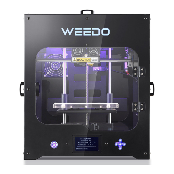
Page 8: Appearance Introduction
Printer Brief Introduction 2.1 Appearance Introduction The Front View of Printer ① ⑧ ② ⑦ ③ ④ ⑤ ⑥ ① ⑤ LCD display screen Up Cover ② ⑥ Control Panel Front Doors Removable Printing Platform ③ ⑦ Left Side Door ④... - Page 9 Printer Brief Introduction The Right View and Back View of Printer ⑥ ① ② ③ ④ ⑤ ① ④ Right Side Door Power Socket ② ⑤ SD Card Socket Host Fan ③ ⑥ USB Line Socket Air Filtration Fan...
-
Page 10: Technical Parameters
Accuracy Power XY axis 0.011mm Filtration Three Layers of Mesh Filter System Consumable Parameters Software Parameters Consumable PLA/PLA Pro Printing Cura WEEDO Version / Type Software ReplicatorG WEEDO Version Consumable 1.75mm File Format STL/GCODE Diameter Consumable Optional for multi-colors Operating... -
Page 11: Installation Of Software
Installation of Software Installation of Software... -
Page 12: The Installation Of Cura Weedo Special
Installation of Software 3.1. The Installation of Cura WEEDO Run the software installation package, Cura-WEEDO, in the installation wizard window, click “installation”→“Next Step”→“Complete”. In the window of selection installation path window, please use the program default route. Note: Cura installation path is the root directory of Disc C... - Page 13 Installation of Software When it is first time to use Cura software, go to the guide interface, click “Next”, go into the computer model selection interface, select WEEDO M2, click “Next”, go to the ready interface, click “Finish”, the installation is...
-
Page 14: Print The First Model
Print the first model Print the first model... -
Page 15: Linked With Power Supply
Print the first model 4.1. Linked with Power Supply Take out the power cord from the accessories box, plug the male connector to the power socket and female connector to 24V wide contact of external power supply, and plug the 24V external power supply circular thin connector to the power supply input socket at the back of printer. -
Page 16: Assembly Of Filament
Print the first model 4.2. Assembly of Filament Take out the tray and rack, put the spindle of material rack on the tray and put all together to the material rack. Find out one end of filament from the material tray and sent it to the feed pipe at the back board of printer, until the filament thread out from another end of material pipe. -
Page 17: Printing Preparation
Print the first model Stuff the excess material filament back to the feeding pipe, and then place the feeding pipe on the feeding hole. 4.3. Printing Preparation Take out the SD memory card presented in accompany with printer, and plug it to the card slot. -
Page 18: Printing Model
Press down the power button at the rear panel, and start up the printer power supply. 4.4. Printing Model On the operation panel, choose “Print the files in the SD card”→”02▁ ThinwallCub.x3g”, press OK button to start printing. WEEDO M2 SD Meun >Print from SD >02_ThinwallCub.x3g Preheat yz50.x3g... -
Page 19: Removing Model
Print the first model 4.5. Removing Model After model is completed with printing, it uses the presented plastic scraper in accompany with printer, to take it out along with the edge of model, or firstly disassemble the printing platform and take out model. -
Page 20: Cura Software Detailed Introduction
Cura Software Detailed Introduction Cura Software Detailed Introduction... -
Page 21: Basic Interface
Cura Software Detailed Introduction 5.1. Basic Interface The figure below displays a typical interface of Cura ◆Red Box is Menu Bar ◆Blue Box is Printing Parameters Setting Bar ◆Yellow Box is used to Adjust model, and to check model ◆Black Box is the operation related to Printing,grey buttons displays it can’t be used temporarily under the current condition. - Page 22 Cura Software Detailed Introduction 5.1.2. Machine Setting Click“Machine”on the menu bar→“Machine Setting”,enter to machine setting interface,as shown in figure below. ◆Blue Box refers to the size of machine printing platform,we have already performed the preset according to your choice of model, please do not change these data.
- Page 23 Cura Software Detailed Introduction 5.1.3. Printing Parameters Settings Click“Advanced Setup”on the menu bar→“Switch to the complete setting model”,go into the complete setting interface, as shown in figure below. ◆Red Box is Printing Quality Parameter. Layer height: is the printing precision we usually refer to, and is generally chosen between 0.1 and 0.25, the smaller the data is, the higher the model precision is.
- Page 24 Cura Software Detailed Introduction ◆Green Box is Support Parameters Support type: shown as figure below, “None” refers to not use the support, “Touching buildplate” is external support, “Everyhere” is complete support, the support type can be choose according to the model suspending in the air. Printing platform adhesive base type: as shown in figure below, “None”...
-
Page 25: Model Conversion
Cura Software Detailed Introduction 5.2. Model Conversion 5.2.1. Model Loading Open Cura software, as shown in figure below, click the loading button of “Load” of red arrow pointing on the interface, the model needed to print is choose in the pop-up window. Please note: Yellow arrow pointing is the progress bar, Cura section engine is always started, when model or parameter is changed, engine would re-start slicing. - Page 26 Cura Software Detailed Introduction 5.2.2. Model Adjustment Red Box is Model Rotation Setting.Click therotation button, and then hold the left key of mouse, and drag the ring shape edge frame around the model to adjust the model, it can perform rotation adjustment to the model from three directions of “X, Y, Z”.
- Page 27 Cura Software Detailed Introduction Blue box is model mirror image, click the mirror image button, three buttons would pop up and they represent the mirror images of three directions of Z, Y, X respectively. Green Box is Check Mode Option Click the button ,five modes buttons, respectively: “Normal”...
- Page 28 Cura Software Detailed Introduction “Overhang” refers to overhang mode, and would indicate the overhang part of model, these part may hang down in the absence of support. The red area pointed by blue arrow is as shown in figure below. “Transparent”...
- Page 29 Cura Software Detailed Introduction “Layers”refers to layered mode, and can watch the movement path of spray-head andsupport structure, as shown in figure below: 5.2.3. Generation of Gcode Code and X3G File Yellow arrow refers to the data which is result of model conversion, including printing the time-consuming and filament use volume.
- Page 30 Cura Software Detailed Introduction When the model generates code of Gcode, the icon blue arrow points changed from grey to white, and it indicates the button can be used, and clicks the button to generate X3G file. When x3g file is generated, it would pop up the progress bar as shown in figure above. After x3g file is completed with save, it would pop up the indication as shown in figure above, namely it is x3g file storage path.
-
Page 31: Operation Panel Setting
Operation Panel Setting Operation Panel Setting There is SD card slot at the right side of 3D printer, which can directly print the model file on the SD card and LCD and control key can perform the filament-replacement, debugging and other operation on the operation panel of machine. -
Page 32: Operation Panel Introduction
Operation Panel Setting 6.1. Operation Panel Introduction WEEDO M2 >Print from SD Preheat Utilities Setting&Info Extruder :020C 3D Printer’s operation panel is composed of LCD display screen and five dimension buttons. In the case of unconnected with computer, it can perform each item of printing operation through operation panel. -
Page 33: Operation Panel Menu
Operation Panel Setting 6.2. Operation Panel Menu The menu tree of control panel is shown as figure below, the menu is divided for three layers (menu structure may be adjusted according to the firmware upgrade), the far left side is the start menu, right side is its sub-menu. When button OK is pressed, it can enter to the sub-menu of certain menu item. -
Page 34: The Common Operation On The Operation Panel
Operation Panel Setting 6.3. The Common Operation on the Operation Panel 6.3.1. Printing Files of the SD Card WEEDO M2 SD Menu >Print from SD >V205.x3g Preheat yz50.x3g Utilities XYtest.x3g Setting&Info XYtest.x3g Extruder :020C Extruder :020C In the start menu, choose the first item of “Printing Files of SD Card”, enter to the SD Card file list. - Page 35 first item “Monitoring Mode”, and enter the real monitoring interface of printer temperature. Press the left button to return the last layer of menu. Utilities WEEDO M2 >Monitor Mode Filament Loading Jog Mode Extruder :020C...
- Page 36 Operation Panel Setting Utilities Unload Monitor Mode >Load >Filament Loading Jog Mode Level Build Plate Extruder :020C Extruder :020C Heating>>> Begin loading or unloading Press’OK’to exit. Choose “Nozzle Filament Return”, press button OK to enter to filament return program. Nozzle is heated to preset temperature, and then start nozzle motor to return filament back.
- Page 37 Operation Panel Setting Jog mode Jog mode <-Y Back <-X Back Z-> The jog debugging interface is divided for three screens, which are corresponding to shaft X, Y and Z, and are switched through left and right buttons. In each shaft debugging interface, pressing up and down buttons can control the two-ways operation of printer shaft motor.
- Page 38 Operation Panel Setting Temperature Offset Setting When the real printing temperature doesn't match with the setting temperature, it can adjust the printing temperature through “Temperature Offset”. In the start menu, choose the forth item “Printer Parameter Information”, enter to the secondary menu, choose the second item “General Settings”, and enter the third level of menu, choose “Temperature Offset”, press button OK to choose this item, press up and down buttons to modify the temperature offset value.
- Page 39 Operation Panel Setting Settings Setting&Info >Sound Bot Statistics Heat LEDs >Settings LED Colour Preheat Settings Accelerate Version Infoemation Extruder :020C Extruder :020C Settings Settings Sound Sound Heat LEDs Heat LEDs LED Colour >LED Colour >Accelerate Accelerate Extruder :020C Extruder :020C Preheating Temperature Settings In the start menu, choose the forth item “Printer Parameter Information”, enter to the secondary menu, choose the third item “Preheating Settings”,...
- Page 40 Operation Panel Setting 6.3.5. The Common Used Parameter Setting in Printing Cancel Printing/Pause Printing Press the left button of operation board, it would pop up option menu, turn down, and choose “Cancel Printing” or “Pause”. Back to Monitor Back to Monitor >Cancel Print Cancel Print Pause...
- Page 41 Operation Panel Setting Modification of Printing Speed Press the left button of operation board, it would pop up option menu, turn down, and choose “Speed Reset”, and enter to printing speed reset interface, press up and down buttons to adjust temperature, the over quick printing speed would damage the printer, please use caution to speed up function.
-
Page 42: Daily Repair And Maintenance
Daily Repair and Maintenance Daily Repair and Maintenance 3D Printer needs to perform the regular maintenance, as well as some daily maintenance, in order to ensure the printer can maintain the high performance to run stably. -
Page 43: Printer Daily Maintenance Guide
Daily Repair and Maintenance 7.1. Printer Daily Maintenance Guide The daily maintenance mainly contains: clean printer nozzle, replace the printer platform sticker and tape, printer platform regular check and leveling, replace air filtration core, optical shaft and screw rod maintenance and others. - Page 44 Daily Repair and Maintenance Tear out tape sticker on the printing platform from the bottom of left side, strip slowly, don't leave any residuals, and then paste the new stickers. Note that it doesn't leave gap between the stickers. 7.1.3. Replacing Air Filtration Core Components The air filtration core components are suggested to be replaced after use 500 hours, otherwise it would lead to dust filtration effect greatly reduced.
- Page 45 Leveling Method: Please place a piece of white A4 paper on the printing platform. In operation panel, choose “Printer Function Debugging” to enter next menu, choose “Platform Leveling”. WEEDO M2 Print from SD Preheat Utilities > Setting&Info...
- Page 46 Daily Repair and Maintenance Homing axis X/Y Adjust front one thumb nuts until nozzles touch, press OK Skip step 2 and step 3, adjust the gap between printing platform and nozzle according to the step 4, step 5, step 6 and step 7 in turn. Adjust two nuts at the back of platform bottom part in synchronization;...
- Page 47 Daily Repair and Maintenance Adjust one nut at the right side of back of platform bottom n, adjust the gap between platforms and nozzle, until A4 paper has slight frictional resistance in sliding. After well adjusted, press button “OK” to enter next step. Adjust right one thumb nuts until nozzles touch press OK...
- Page 48 Daily Repair and Maintenance Finished, Press OK After adjustment is completed, if feel it is not appropriate to the gap between platform and nozzle, please re-calibrate each position. Calibration Complete Press To Continue 7.1.5. Optical Shaft and Screw Rod Maintenance In the process of using printer, the two directions of X and Y depends on the precise guide rail and shaft X screw rod to ensure stable and precise rectilinear motion.
-
Page 49: Printing Nozzle Maintenance And Replacement
Daily Repair and Maintenance 7.2. Printing Nozzle Maintenance and Replacement After printer has been used for a long time, as feed gear continues to convey and rub the filament, on the gear would be pasted with filament powder, which leads to gear becomes weak in holding power and affect the transmission effect. - Page 50 Daily Repair and Maintenance Then, take out the whole motor and feed gear from right back side The filament debris on the motor gear is performed with cleaning by tweezers, and installed is performed according reverse procedures after cleaning. Note: Finally plug in the motor connection line. 7.2.2.
- Page 51 Daily Repair and Maintenance Take out the whole component of nozzle from the bottom and pull out the connecting line plug of nozzle. The process of nozzle disassembly is over.
- Page 52 Daily Repair and Maintenance The Installation Process of New Nozzle Components: The throat pipe part of new nozzle is inserted into the aluminum block from the bottom, the top of throat pipe closely contacts with the bottom of motor gear ;and then screw down the screw of fixed throat pipe. The whole process is over.
-
Page 53: Frequently Asked Questions And Troubleshooting (Faq)
Frequently Asked Questions and Troubleshooting (FAQ) - Page 54 1.Should the filament replacement operation be run for operating the printer each time? The filament replacement operation should not be run for startup of printer each time, but only be used in thefilament replacement. 2.After the model is completed with printing, can it be taken down the model by hand immediately? Please do not get model by hand immediately, please wait the model cooling for a moment, and gently shovel away the model by scraper;...
- Page 55 1)The filament materials are used up, which shows the filament material is left in the printer nozzle. Please disassemble the fan above the printing nozzle, and take off the printing nozzle and then heat the printer nozzle to 230℃, use plier to pull out the filament section carefully.
- Page 56 OFFICAL WEBSITE www.weedo.ltd SERVICE CALL 86 400 816 3066 COMPANY ADDRESS Jiangsu wiiboox technology co., Ltd 180# LONGMIAN ROAD, JIANGNING, NANJING, 211100, CHINA...
Need help?
Do you have a question about the M2 and is the answer not in the manual?
Questions and answers
The weedo is making screeching noise when printing. It use to be quiet. Cause?