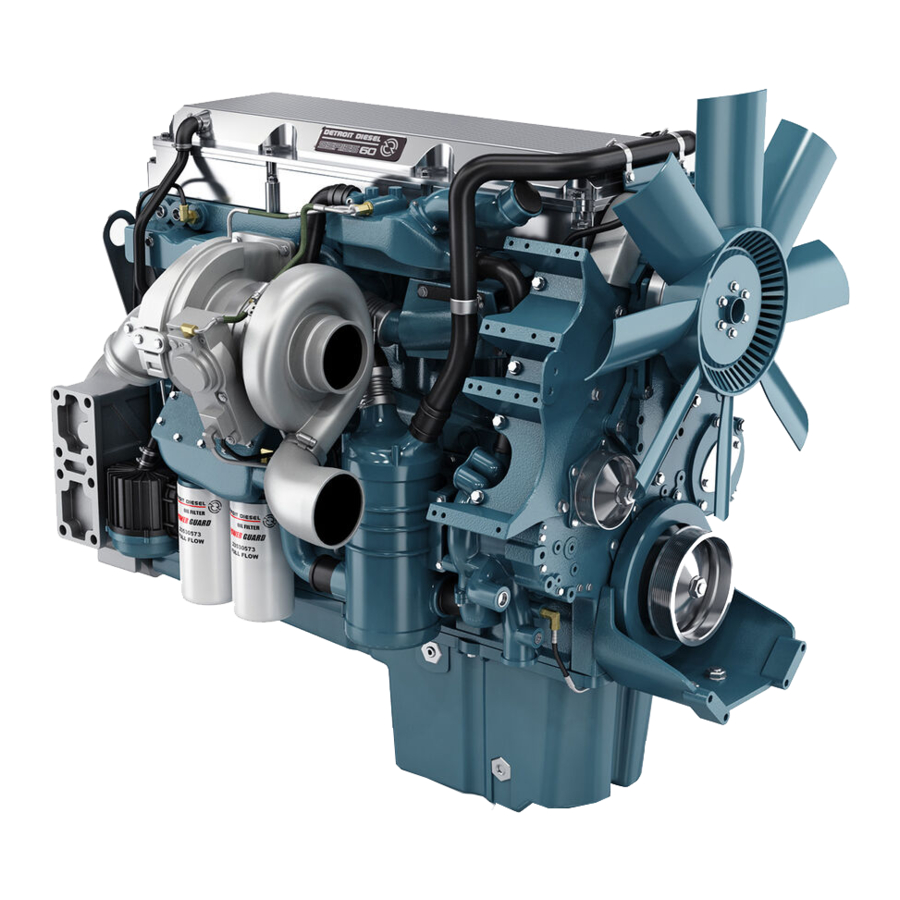
Detroit Diesel Series 60 Service Manual
Hide thumbs
Also See for Series 60:
- Service manual (1669 pages) ,
- Operator's manual (172 pages) ,
- Owner's manual (24 pages)
Table of Contents
Advertisement
NUMBER: 11–60–02 S.M. REF.: 1.23 ENGINE: 60 DATE: December 2002
SUBJECT: COMPACT GEAR TRAIN ASSEMBLY
INTRODUCTION
Detroit Diesel has released a new Compact Gear Train Assembly for the Series 60 2002 engine. This
new assembly offers weight savings, noise reduction and height reduction. The bullgear is a straight cut
gear that now rides on bushings.
DETAILS AND REASON
Series 60 2002 Engines are equipped with a new Compact Gear Train Assembly. Camshaft, Camshaft
Drive Gear and Camshaft Gear Cover will be installed and removed as a assembly.
For engines equipped with a Compact Gear Train Assembly remove camshaft assembly as follows.
1. Rotate the engine by hand to get the No. 1 piston at TDC. Do this by installing the crankshaft
timing pin J 45947 into its bracket and the barring engine over by hand until the timing pin
drops into the locating hole in the crankshaft, the engine is now at TDC on cylinder No.1.
See Figure 1.
Advertisement
Table of Contents

Related Manuals for Detroit Diesel Series 60


Summary of Contents for Detroit Diesel Series 60
- Page 1 SUBJECT: COMPACT GEAR TRAIN ASSEMBLY INTRODUCTION Detroit Diesel has released a new Compact Gear Train Assembly for the Series 60 2002 engine. This new assembly offers weight savings, noise reduction and height reduction. The bullgear is a straight cut gear that now rides on bushings.
- Page 2 1. Timing Pin Figure 1 Crankshaft Timing Pin 2. Remove the five bolts for the camshaft gear cover inspection plate and remove the plate. To verify camshaft timing proceed as follows: [a] Look at the timing hole in the camshaft gear. [b] The timing hole should be aligned with the timing hole in the back of the gear cover, located at the 5 o'clock position.
- Page 3 [c] If the timing holes are not aligned correctly remove the crankshaft timing pin and rotate the engine one more complete revolution. When the timing pin drops back into the hole in the crankshaft check the timing of the camshaft. Refer to step 2. 1.
- Page 4 3. Remove bolt from front of camshaft gear cover. See Figure 3. 1. Bolt 2. Camshaft Gear Cover Figure 3 Camshaft Gear Cover Bolt NOTE: If timing is correct and the repair being made does not require that the engine is turned over, clean off an area where the camshaft gear and idler gear teeth mesh and mark the teeth with a suitable marker for a reference point when reassembling the camshaft.
- Page 5 4. Remove four camshaft gear cover bolts. See Figure 4. 1. Bolt Figure 4 Camshaft Gear Cover Bolts...
- Page 6 5. Remove three bolts inside of camshaft gear cover. See Figure 5. 1. Bolt Figure 5 Camshaft Gear Cover Bolts...
- Page 7 6. Remove one bolt and one stud bolt from camshaft caps No.1 and 7, remove camshaft caps. See Figure 6. 1. Bolt 2. Stud Bolt Figure 6 Camshaft Cap Bolt and Stud Bolt 7. Remove the remaining five camshaft cap bolts, and camshaft caps. To avoid injury when removing or installing a heavy engine component, ensure the component is properly supported and securely attached to an adequate lifting device to prevent...
- Page 8 For Series 60 engines equipped with Compact Geartrain Assembly disassemble camshaft from the camshaft gear as follows. 1. Use suitable fixture to secure the camshaft assembly from movement. 2. Install a heavy duty gear puller capable of withstanding the 7000 PSI required to remove the gear from the camshaft.
- Page 9 For engines equipped with the new Compact Geartrain Assembly install camshaft assembly on engine as follows: 1. Install camshaft alignment tool J 45946 on the camshaft gear cover and through the camshaft gear, making sure the pin on the tool is entered into the timing hole in the backside of the camshaft gear cover.
- Page 10 NOTICE: Do not bar the engine over with the timing pin installed. The timing pin is designed to break and will not damage the crankshaft. 2. Verify timing pin is in crankshaft locator hole. See Figure 8. 1. Timing Pin Figure 8 Crankshaft Timing Pin 3.
- Page 11 4. Ensure two seals are properly installed in camshaft gear cover. See Figure 9. Figure 9 Camshaft Seals...
- Page 12 5. Apply RTV along split line on gear case. See Figure 10. 1. RTV Sealant 4. Lifting Tool 2. Seal 5. Camshaft 3. Camshaft Gear Cover Figure 10 Apply RTV Sealant along Split line NOTE: Camshaft gear cover assembly must be installed promptly to avoid the setting of the RTV. To avoid injury when removing or installing a heavy engine component, ensure the component is properly supported and securely attached to an adequate lifting device to prevent...
- Page 13 6. Install two guide studs J 46302 into gearcase to guide camshaft gear cover assembly onto gearcase. Using lifting tool J 46305 place front lifting hook between the number 2 injector lobe and intake valve and the rear hook between the number 4 injector lobe and intake valve, lower camshaft assembly into position on bearings and gear case.
- Page 14 NOTE: Verify alignment tool is installed correctly. Incorrect installation will result in gear not being in time and the procedure will need to be repeated. 1. Camshaft Gear Cover 2. Timing Hole Figure 11 Timing Verification...
- Page 15 For Series 60 engines equipped with Compact Gear Train Assembly install camshaft bearing caps as follows: ® 8. Apply RTV to grooves in camshaft cap No. 1 and Gasket Eliminator to camshaft cap No.7. See Figure 12. Figure 12 Sealant Application...
- Page 16 9. Install No. 1 and 7 camshaft bearing caps with one bolt and one stud bolt in each and tighten. See Figure 13 1. Bolt 2. Stud Bolt Figure 13 Camshaft Bearing Cap Bolt and Stud Bolt 10. Install the remaining five camshaft caps onto cylinder head with one bolt for each camshaft cap. 11.
- Page 17 12. Install three bolts inside camshaft gear cover and torque to 10 N·m (7 lb·ft). See Figure 14. 1. Bolt Figure 14 Camshaft Gear Cover Bolts...
- Page 18 13. Install four camshaft gear cover bolts torque to 56-66 N·m (44-48 lb·ft) using torque sequence as shown in Figure 15. Figure 15 Bolt Torque Sequence...
- Page 19 14. Torque the three bolts previously installed inside camshaft gear cover to 56-66 N·m (44-48 lb·ft). See Figure 16. 1. Bolt Figure 16 Camshaft Gear Cover Bolts...
- Page 20 Additional service information is available in the Detroit Diesel Series 60 Service Manual, 6SE483. The next revision to this manual will include the revised information. As a convenience to holders of the Series 60 Service Manual, information in service manual format is attached. The page(s) may be inserted into the manual.
- Page 21 NOTE: Manual insert pages are numbered for insertion into the current Series 60 Service Manual dated April 2002. Service manuals are available from authorized Detroit Diesel distributors. If this bulletin was obtained from the Internet, service manual page(s) are available by returning to the screen “SIB...
- Page 22 ® ® ® Detroit Diesel , DDC , Series 60 and the spinning arrows design are registered trademarks of Detroit Diesel Corporation. © Copyright 2002 Detroit Diesel Corporation. All rights reserved. Printed in U.S.A.
Need help?
Do you have a question about the Series 60 and is the answer not in the manual?
Questions and answers