Table of Contents
Advertisement
Changes in this Issue
• New Service Manual
• New Model Added
Service
Information
© 2016 Reg. Office: Peterborough PE2 9JB Registered in London: 106725
Whirlpool UK Appliances Ltd
5413450 Issue 1
C00383263 ~ SM031321
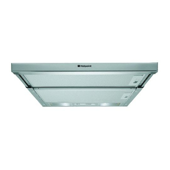
HOTPOINT
60 cm
TELESCOPIC
COOKER HOOD
Model
Covered
HSFX.1
May 2016
Comm.
Code
88215
Advertisement
Table of Contents

Related Manuals for Hotpoint HSFX.1


Summary of Contents for Hotpoint HSFX.1
- Page 1 HOTPOINT 60 cm TELESCOPIC COOKER HOOD Model Comm. Covered Code HSFX.1 88215 Changes in this Issue • New Service Manual • New Model Added Service Information Whirlpool UK Appliances Ltd © 2016 Reg. Office: Peterborough PE2 9JB Registered in London: 106725...
-
Page 2: Serial Number / Industrial Code Explanation
Whirlpool UK Appliances Ltd SAFETY NOTES & GENERAL SERVICING ADVICE 1. This manual is NOT intended as a comprehensive repair/maintenance guide to the appliance. 2. It should ONLY be used by suitably qualified persons having technical competence applicable product knowledge and suitable tools and test equipment. 3. -
Page 3: Table Of Contents
Whirlpool UK Appliances Ltd INDEX Serial Number / Industrial Code Explanation ........2 Introduction . -
Page 4: Introduction
Whirlpool UK Appliances Ltd INTRODUCTION OF HOTPOINT COOKER HOOD - HSFX.1 This model was introduced into the Hotpoint built in range in October 2015. It has 3 speed, slider controls with 2 x 28W lights. This model replaces HSFX. SPECIFICATIONS... -
Page 5: Disposal
Whirlpool UK Appliances Ltd DISPOSAL To minimise the risk of injury to children please dispose of your product carefully and safely. Remove all doors and lids. Remove the mains cable (where fitted) by cutting off flush with the appliance and always ensure that no plug is left in a condition where it could be connected to the electricity supply. -
Page 6: Installation
Whirlpool UK Appliances Ltd INSTALLATION OF THE COOKER HOOD Components not supplied with the product Service Manual UK English 6 of 25... - Page 7 Whirlpool UK Appliances Ltd INSTALLATION OF THE COOKER HOOD Service Manual UK English 7 of 25...
- Page 8 Whirlpool UK Appliances Ltd INSTALLATION OF THE COOKER HOOD continued Service Manual UK English 8 of 25...
- Page 9 Whirlpool UK Appliances Ltd INSTALLATION OF THE COOKER HOOD continued Service Manual UK English 9 of 25...
- Page 10 Whirlpool UK Appliances Ltd INSTALLATION OF THE COOKER HOOD continued Service Manual UK English 10 of 25...
- Page 11 Whirlpool UK Appliances Ltd INSTALLATION OF THE COOKER HOOD continued Service Manual UK English 11 of 25...
-
Page 12: General Safety
Whirlpool UK Appliances Ltd ELECTRICAL CONNECTION IMPORTANT: - This appliance must be Earthed. The mains power supply must correspond to the rating indicated on the plate situated inside the hood. If provided with a plug connect the hood to a socket in compliance with current regulations and positioned in an accessible area. - Page 13 Whirlpool UK Appliances Ltd The use of exposed flames is detrimental to the filters and may cause a fire risk, and must therefore be avoided in all circumstances. Any frying must be done with care in order to make sure that the oil does not overheat and ignite. CAUTION! Accessible parts of the hood may become hot when used with cooking appliance.
-
Page 14: How To Get The Best Out Of The Cooker Hood
Whirlpool UK Appliances Ltd HOW BEST TO USE THE COOKER HOOD Correct use and maintenance of the hood require a few very simple operations, allowing the product to reach its full potential. Incorrect Use Correct Use Switching on the hood only when there are The hood must ALWAYS be switched on when unpleasant odours. -
Page 15: Connection
Whirlpool UK Appliances Ltd CONNECTION AIR VENT (for the suction versions) Connect the hood and discharge holes on the walls with a diameter equivalent to the air outlet (connection flange). Using the tubes and discharge holes on walls with smaller dimensions will cause a diminution of the suction performance and a drastic increase in noise. -
Page 16: Controls
Whirlpool UK Appliances Ltd CONTROLS The hood is fitted with a control panel with aspiration speed selection control and a light switch to control cooking area lights. Use the high suction speed in cases of concentrated kitchen vapours. It is recommended that the cooker hood suction is switched on for 5 minutes prior to cooking and to leave in operation during cooking and for another 15 minutes approximately after terminating cooking. -
Page 17: Maintenance
Whirlpool UK Appliances Ltd MAINTENANCE ATTENTION: - Before performing any maintenance operation, isolate the hood from the electrical supply by switching off at the connector and removing the connect or fuse. Or if the appliance has been connected through a plug and socket, then the plug must be removed from the socket. Cleaning The cooker hood should be cleaned regularly (at least with the same frequency with which you carry out maintenance of the fat filters) internally and externally. -
Page 18: Malfunctions
Whirlpool UK Appliances Ltd Replacing the Lamps Disconnect the hood from the electricity supply. Warning: - Prior to touching the light bulbs, ensure that they are cooled down. Replace the old light bulb with one of the same type as the original. Extend the drawer completely. -
Page 19: Wiring Diagram
Whirlpool UK Appliances Ltd WIRING DIAGRAM White Blue Black Blue Yellow Connector Blue Blue Yellow Brown Micro Switch Blue Grey Push Button Blue Grey White Grey Grey Blue SEL0060629 Black Yellow Brown Blue Service Manual UK English 19 of 25... -
Page 20: Other Items Supplied
Whirlpool UK Appliances Ltd ITEMS SUPPLIED Service Manual UK English 20 of 25... -
Page 21: Dismantling Procedure
Whirlpool UK Appliances Ltd SERVICING & DISMANTLING PROCEDURES Safety Notes 1. Refer to Safety Notes and General Servicing Advice on page 2. 2. To undertake any dismantling, with the exception of the lamp and filter replacement, it is recommended to remove the hood from its location and place on a protected surface. Lamp Replacement To gain access to the lamps, gently prise off the plastic cover using a small screwdriver, taking care not to scratch the surface of the hood itself. - Page 22 Whirlpool UK Appliances Ltd Remove the lamp wiring cover by disengaging the 4 tabs and lifting away. Lift the lamp holder out of its location and replace. Reassemble in reverse order. Motor Replacement Invert the hood and place upon a protected surface. Remove the grease filter and carbon filters (if fitted).
- Page 23 Whirlpool UK Appliances Ltd Remove the lamp wiring cover by disengaging the 4 tabs and lifting away. Disconnect the motor wiring. Lift away both the mains socket and motor plug. Access to a motor cover securing tab should now be possible. Separate the two motor cover halves by releasing all the remaining tabs.
- Page 24 Whirlpool UK Appliances Ltd Unscrew the fan motor fixing nuts (7mm). m) Replace the faulty component and reassemble in reverse order. Slider Replacement Invert the hood and place upon a protected surface. Remove the grease filter and carbon filters (if fitted). If required, the front panel (with logo) can be replaced by unscrewing the 2 securing screws.
- Page 25 Whirlpool UK Appliances Ltd Push Button Control Panel & Buttons Invert the hood and place upon a protected surface. Remove the grease filter and carbon filters (if fitted). It is recommended to remove the slider assembly at this point (4 screws) and also the lamp cover surround, 2 screws T10.
Need help?
Do you have a question about the HSFX.1 and is the answer not in the manual?
Questions and answers