Table of Contents
Advertisement
Quick Links
INSTALLATION GUIDE
SCXI-1303 32-C
T
B
ERMINAL
Introduction
What You Need to Get Started
CVI ™, LabVIEW ™, NI-DAQ ™, and SCXI ™ are trademarks of National Instruments Corporation. Product and company names are trademarks or
trade names of their respective companies.
321923A-01
HANNEL
LOCK
This guide describes how to install and use the SCXI-1303 terminal block
with SCXI-1102,SCXI-1102B, SCXI-1102C, and SCXI-1100 modules.
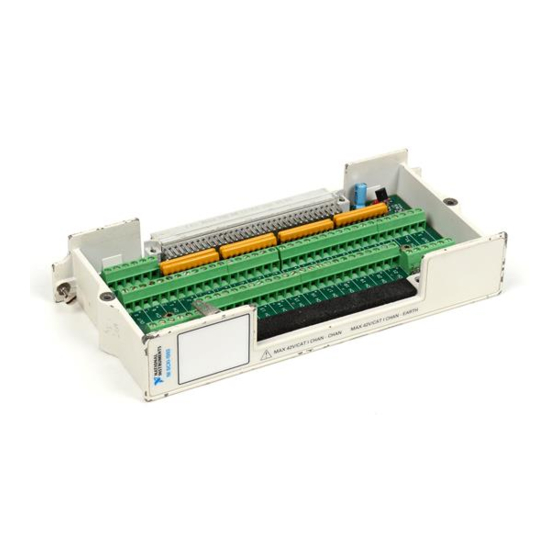
The SCXI-1303 32-channel isothermal terminal block is a shielded board
with screw terminals that connect to the SCXI-1102/B/C and the
SCXI-1100 modules. The SCXI-1303 has a high-accuracy thermistor,
cold-junction temperature sensor, and an isothermal copper plane to
minimize the temperature gradients across the screw terminals when you
measure with thermocouples.
The terminal block has 78 screw terminals for easy connection. Thirty-two
pairs of screw terminals connect to the 32 differential inputs of the SCXI
modules. One pair of terminals connects to the module's chassis ground
pins. Three terminals connect to the SCXI module OUTPUT and AOREF
pins and to the SCXIbus guard. All of the other terminals—OUT0+,
OUT0–, OUT1+, OUT1–, OUT2+, OUT2–, OUT3+, OUT3–, and
AIREF—are reserved for future use.
The terminal block has a pullup resistor connected between CH+ and +5 V
and a bias resistor connected between CH– and chassis ground. These
resistors help you detect open thermocouples by detecting saturation of the
module amplifier output.
To set up and use your SCXI-1303, you will need the following items:
SCXI-1303 32-channel isothermal terminal block
SCXI-1303 32-Channel Isothermal Terminal Block Installation Guide
© Copyright 1998 National Instruments Corp. All rights reserved.
I
SOTHERMAL
August 1998
Advertisement
Table of Contents

Related Manuals for National Instruments SCXI-1303


Summary of Contents for National Instruments SCXI-1303
- Page 1 SCXI-1303 32-channel isothermal terminal block SCXI-1303 32-Channel Isothermal Terminal Block Installation Guide CVI ™, LabVIEW ™, NI-DAQ ™, and SCXI ™ are trademarks of National Instruments Corporation. Product and company names are trademarks or trade names of their respective companies.
-
Page 2: Changing Resistor Networks
10 MΩ Resistor Network Figure 1. Resistor Networks Open Thermocouple Detection The SCXI-1303 circuitry helps you detect an open thermocouple. To detect whether any thermocouple is open, check whether the corresponding SCXI module channel is saturated. The SCXI-1303 has pullup and bias resistors that saturate the channel by applying +5 V at the input of the open channel. - Page 3 200 µs at a gain of 100 or higher, which corresponds to a sample rate of 5 kHz. With the 10 Ω bias resistors installed in the SCXI-1303, you can measure accurately at the module’s maximum sampling rate, but the open thermocouple channel may not saturate if the interchannel delay is less than 200 µs or if the sample rate is more than 5 kHz at a gain of 100 or...
-
Page 4: Temperature Sensor Output And Accuracy
Temperature Sensor Output and Accuracy The SCXI-1303 temperature sensor outputs 1.91 to 0.58 V from 0° to 55° C and has an accuracy of ±0.5° C over the 15° to 35° C range and ±0.9° C over the 0°... -
Page 5: Configuring The Resistor Networks
Configuring the Resistor Networks Note A package of 10 MΩ resistor networks is included in the SCXI-1303 kit. If you are using the SCXI-1102/B/C module, you can install these resistor networks as RP1, RP2, RP3, and RP4. With this recommended configuration, it does not matter whether the thermocouples are ground-referenced or floating. - Page 6 Table 1. Channel Input Signals and Resistor Networks Pullup Resistor Channel Network Bias Resistor Network 0–7 8–15 16–23 24–31 Table 2 shows which resistor networks to use for your SCXI module, signal type, and application. SCXI-1303 Installation Guide © National Instruments Corporation...
-
Page 7: Signal Connection
Signal Connection When connecting your signals to the SCXI-1303, follow the labeling on the SCXI-1303 for the appropriate module, as indicated in Figure 4. To connect the signal to the terminal block, perform the following steps, referring to Figures 3 and 4 as necessary: Unscrew the top cover screws and remove the cover. - Page 8 Reinstall the top cover and tighten the top cover screws. 10. Connect the terminal block to the module front connector as explained in the Installation section later in this guide. Figure 3 shows the SCXI-1303 terminal block parts locator diagram. Back View Front View...
-
Page 9: Installation
Figure 4 shows the SCXI-1303 signal connections. - Pin 1 1 Screw Terminals 3 Pullup Resistor Networks 4 Product Name, Assembly 2 Bias Resistor Networks Number, Revision Letter, and Serial Number. Figure 4. SCXI-1303 Signal Connections Installation To connect the terminal block to the SCXI module front connector, perform... -
Page 10: Cleaning The Terminal Block
Repeatability........0.2° from 15° to 35° C Output ..........1.91 to 0.58 V from 0° to 55° C Temperature Sensor Circuit Diagram The circuit diagram in Figure 5 provides optional details about the SCXI-1303 temperature sensor. +5 V 4.7 kΩ 2.5 V 5 kΩ...
Need help?
Do you have a question about the SCXI-1303 and is the answer not in the manual?
Questions and answers