
Subscribe to Our Youtube Channel
Related Manuals for TurboChef FRE-1002D


Summary of Contents for TurboChef FRE-1002D
- Page 1 Service Manual fo r t h e tu rb o c h ef f ir e o v e n CAUTION: Read the instructions before using the machine. ©2014-2015 TurboChef Technologies, Inc.
- Page 3 For further information, call 800.90 TURBO +1 214.379.6000...
- Page 4 Original Instructions The information contained in this manual is important for the proper installation, use, maintenance, and repair of this oven. Follow these procedures and instructions to help ensure satisfactory baking results and years of trouble-free service. Errors – descriptive, typographic, or pictorial – are subject to correction. Specifications are subject to change without notice.
-
Page 5: Table Of Contents
Table of Contents Important Safety Instructions General Safety Information Reducing Fire Risk Grounding Instructions Power Cord Replacement or Removal Protective Earth (Ground) Symbol Equipotential Bonding Symbol Specifications and Installation Performance Dimensions Certifications Oven Construction Electrical Specifications Installation Unpacking Instructions Installation Warnings - Read Before Lifting Oven Lifting and Placing the Oven Installation Near Open Heat Source Voltage Selection... - Page 6 Oven Schematics Appendix - Replacing Oven Components Replacing Oven Components Replacing Items...
-
Page 7: Important Safety Instructions
IMPORTANT SAFETY INSTRUCTIONS WARNING: When operating this oven, strictly adhere to the following safety precautions to reduce the risk of burns, electric shock, fire, injury, or damage to oven or property near oven. WARNING: This appliance has hot surfaces! During use, the accessible parts of the oven can get very hot. -
Page 8: Reducing Fire Risk
SAFETY INSTRUCTIONS Reducing Fire Risk I f materials inside the oven ignite, keep the oven door closed, turn the oven off, and disconnect the power cord or shut off power at the fuse or circuit breaker panel. I f smoke is observed, switch off or unplug the oven. Keep the door closed to stifle any flames. DO NOT put plastic or paper bags in the oven. -
Page 9: Specifications And Installation
Specifications and Installation... -
Page 11: Performance
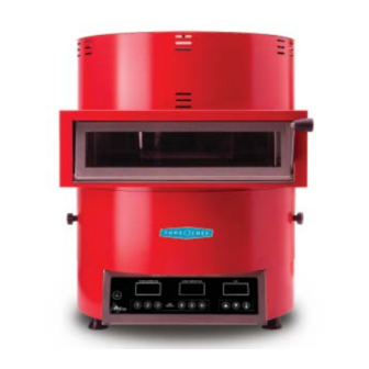
10.95” (278.1 mm) 18.55” (471.2 mm) Figure 1: Fire Oven Dimensions Performance Dimensions The TurboChef Fire provides the artisan hearth- Oven Dimensions style pizza experience anywhere. Cooking at Height: 22.7” (576.6 mm) Width: 19.01” (482.9 mm) 842°F/450°C, the Fire can cook 14-inch fresh Depth (footprint): 18.55”... -
Page 12: Certifications
- Powder coated, corrosion-resistant steel outer placed on a food station at all times. wrap and door TurboChef will not recognize a fallen oven as - 430 stainless steel construction a warrantable claim and is not liable for any injuries that may result. -
Page 13: Installation Near Open Heat Source
Installation Near Open Heat Source Ventilation When placing a TurboChef oven near an open The TurboChef Fire oven has been approved by heat source (Figure 2), strictly adhere to the Underwriter’s Laboratory LLC for ventless following: operation (UL® KNLZ listing) for all food items except for foods classified as “fatty raw proteins.”... -
Page 14: Installing The Oven Handle
SPECIFICATIONS AND INSTALLATION Installing the Oven Handle 1. While the oven is off and cool, open the oven door (Figure 3). 2. Using a flat-head screwdriver, remove the two screws on the outside of the oven door (Figure 3). Oven Door Screws 3. -
Page 15: Daily Maintenance
Daily Maintenance... -
Page 17: Supplies And Equipment
• Use a food vacuum or damp towel to remove large particles from the oven interior. Step 3: Clean the Oven Interior • Spray TurboChef ® Oven Cleaner onto a clean towel or nylon scrub pad and scrub the interior of the oven and the inside portion of the lower access panel. - Page 18 DAILY MAINTENANCE This page intentionally left blank.
-
Page 19: Oven Operation
Oven Operation... -
Page 21: Oven Controls
UPPER TEMPERATURE LOWER TEMPERATURE TIME TIME PRESETS Figure 7: Oven Controls Oven Controls 5. Upper Temperature Display Displays the current Upper Temperature. A green 1. On/Off Key light in the lower-left corner of this display will Press to turn the oven on or off. blink during warmup and turn solid once it has reached the set temperature. -
Page 22: Setting The Temperatures
OVEN OPERATION Setting the Temperatures Two different temperatures can be set: one for the upper heating zone and one for the lower heating zone. These temperatures range from off to 842°F (450°C). NOTE: When a temperature is set to off, the display will read 32°F (0°C). To set the temperature: 1. - Page 23 Parameter Description Unit of Measure Minimum Value Maximum Value Default Value Temperatures shown in °C or °F (0 = °C, 1 = °F) Temperatre Displays (0 = Actual, 1 = Setpoint) Hysteresis Setting for Thermostat °F/°C 36°F/2°C 48°F/9°C 4°F/2°C Off set of Top RTD °F/°C -22°F/-30°C 86/°F30°C...
-
Page 24: Front Panel Light Indicators
OVEN OPERATION Front Panel Light Indicators Each display (Upper Temperature, Lower Temperature, and Time) has three lights in the lower-left corner. From left to right, the lights are green - yellow - green. Upper Temperature Lights: Left (Green) - Flashes during preheat. Turns solid when the oven reaches the set temperature. Middle (Yellow) - Not used. - Page 25 Troubleshooting...
-
Page 27: Troubleshooting Fault Code Er1
Troubleshooting: Fault Code Er1 Er1 is displayed on the upper temperature display and indicates a damaged upper RTD. The oven will beep when this error occurs. Is the wiring from the Is the upper RTD upper RTD to the control operating properly? Replace the RTD. -
Page 28: Fault Code Ht
TROUBLESHOOTING Troubleshooting: Fault Code Ht Ht is displayed on the upper temperature display and indicates that the temperature in the controls compartment is too hot. The oven will beep when this error occurs. Is the wiring from the Is the wiring from the Is the controls controls compartment controls compartment... -
Page 29: Food Not Cooking Properly
Troubleshooting: Food Not Cooking Properly Use the following troubleshooting steps when the oven is not cooking properly. Does the problem occur with all items? For example, everything is undercooked/ overcooked/etc.? Are there any fault codes present? See pages 10-11. Is the food item in the correct starting state (e.g., frozen, fresh, etc.)? Troubleshoot the... - Page 30 TROUBLESHOOTING This page intentionally left blank.
- Page 31 Oven Schematic...
- Page 33 DWG NO FRE-1161-1 REVISIONS DESCRIPTION DATE APPROVED NOTES: ECN 1507-021 02-19-15 PRODUCTION RELEASE ECN 1509-031 09-30-15 CHANGED TO MATCH PRODUCTION BLU (L2) RED (L1) RED (L1) BLU (-) TOP RTD BOTTOM RTD RED (+) RED (+) VOLTAGE SELECTOR BRN (L1) RED (+24) BLK (-24) BLU (L2)
- Page 34 OVEN SCHEMATIC DWG NO FRE-1161-1 REVISIONS DESCRIPTION DATE APPROVED NOTES: ECN 1507-021 02-19-15 PRODUCTION RELEASE ECN 1509-031 09-30-15 CHANGED TO MATCH PRODUCTION +12VAC POWER IN J12B J10B SIGNATURE DATE DRAWN TITLE CHECKED SCHEMATIC, FIRE ENGINEER 208/240 VAC 1 PH 60HZ PRODUCTION SIZE CODE IDENT NO...
- Page 35 Appendix Replacing Oven Components...
- Page 37 It also includes the item numbers and descriptions for the fasteners used to secure each component to the oven chassis. If you have any questions that are not addressed in this manual or appendix, please contact TurboChef Customer Service at 800.90TURBO or +1 214.379.6000.
- Page 38 APPENDIX - REPLACING OVEN COMPONENTS Replacing Items DANGER: Before replacing any oven component, ensure the oven is removed from any power source. Replacing a component while the oven is plugged in can result in serious injury or death CAUTION: Be careful to not tear the insulation when servicing components. Always reinstall the insulation properly before reinstalling the outer shell.
- Page 39 Figure Fastener Part Item Description Item Part Number Fastener Description Reference # Number(s) Cover, Back FRE-1016 Screw, M4x10mm LG, PPHD, S.S. 101671 (qty 8) Cover, Bottom FRE-1133 Screw, M4x10mm LG, PPHD, S.S. 101671 (qty 7) FRE-1059-1 (Red) FRE-1059-2 (Green) FRE-1059-3 (Yellow) Cover, Top Screw, M4x10mm LG, PPHD, S.S.
- Page 40 +1 214.379.6000 or Your Authorized Distributor Global Operations TurboChef International Customer Support 280 1 T r a d e C en t e r Dr i v e B us in es s &...
Need help?
Do you have a question about the FRE-1002D and is the answer not in the manual?
Questions and answers