Table of Contents
Advertisement
Quick Links
Advertisement
Chapters
Table of Contents

Subscribe to Our Youtube Channel
Related Manuals for Mitsubishi S6R Series


Summary of Contents for Mitsubishi S6R Series
- Page 1 SERVICE MANUAL 199419-12120 August 2010 Pub. No. 99419-12120...
- Page 2 FOREWORD This service manual describes the maintenance and adjustment procedures, and specifi- cations for Mitsubishi diesel engines. To maintain the performance of the engine for many years and to ensure safe operation, it is important to use the engine correctly and conduct scheduled inspection and mainte- nance, and it may also be necessary to take appropriate measures which involve in disas- sembly, inspection, repair and assembly work of the engine and engine parts.
-
Page 3: How To Use This Manual
HOW TO USE THIS MANUAL This service manual consists of several chapters, which will give you quick references to specifications, maintenance standards, adjustment and service procedures including practices to disassemble, inspect, repair and assemble the Mitsubishi diesel engines. A short summary describing the contents of each chapter is given in the CHAPTER INDEX page, and there is also a detailed table of contents at the beginning of each chapter. - Page 4 FOREWORD Terms used in this manual Nominal value means the basic nominal size of a part to be measured. Standard value means the quantitative requirement for dimension of a part, clearance between parts and performance. The values are rounded off for the inspection job, and do not necessarily conform to the design values. Limit value means the limit value, which the measured value reaches, the part needs repair or replacement with a new one.
- Page 5 FOREWORD Safety Cautions Fire and Explosion Precautions Pay Attention to Fuel, Oil and Exhaust Gas Keep Flames Away Do not use flames near the engine (in Leak the engine room). The flame is dan- If any fuel, oil or exhaust gas leakage is found, imme- gerous to ignite combustibles and diately take corrective measures to stop it.
- Page 6 FOREWORD Stay Away From Rotating and Moving Parts Lockout and Tagout Install Protective Covers Over Rotating Be sure to lockout and tagout before starting inspec- Parts After Inspection and Maintenance tion and maintenance. Lockout and tagout are effec- Work tive methods of cutting off machines and equipment Check the covers over engine rotating from energy sources.
- Page 7 FOREWORD Be Careful of Falling Be Careful of Exhaust Gas Poison- Lift Engine Carefully Use slings or wire ropes strong Be Careful of Ventilation to Operate Engine enough to lift the load considering the If the engine is installed in an engine weight.
- Page 8 FOREWORD Be Careful of Burns Be Careful When Handling Fuel, Engine Oil or LLC Do Not Touch the Engine During or Immedi- Use Specified Fuel, Engine Oil and Long- ately After Operation Life Coolant (LLC) Only Do not touch any parts of the engine during or immediately after operation.
- Page 9 FOREWORD When Abnormality Occurs Battery Do Not Add Coolant Immediately After a Be Careful with Battery Sudden Stop Due to Overheating Never use flames or generate sparks near the battery. The bat- If the engine stops suddenly due to overheating, or tery gives off highly flammable you suddenly stop the engine by any reason, do not hydrogen gas and oxygen gas.
- Page 10 FOREWORD Other Cautions Never Break the Seals Do Not Tamper To ensure the proper engine operation, the fuel control If tampered, the warranty is totally void even in the link is provided with seals that protect the fuel injection warranty period. Tampering with the engine can not volume and rotation speed settings against tampering.
- Page 11 FOREWORD Use Care to Protect Engine From Water Warm-up the Engine Before Use Use care to protect engine from water such as rain After starting the engine, run the engine at a low idling entering through the air inlet or exhaust openings. Do speed for 5 to 10 minutes for warming-up.
- Page 12 FOREWORD Cautions for Engine Transportation Observe Safety Rules at Work Site To road-transport the engine, consider the engine Observe the safety rules established at the workplace weight, width and height, and obey applicable laws when operating and maintaining the engine. Do not and regulations such as road traffic laws, vehicle road operate the engine if you are in bad health.
-
Page 13: Warning Labels
FOREWORD Warning Labels Maintenance of Warning Labels Make sure all warning/caution labels are legible. Clean or replace the warning or caution label when the description or illustration is not clear to read. For cleaning the warning/caution labels, use a cloth, water and soap. Do not use cleaning solvent, gasoline or other chemicals to prevent the label from fading and peering. - Page 14 FOREWORD Points on Disassembling and Assembling This service manual contains the recommended practices to Points on Assembling service the engine. The manual also contains dedicated spe- Wash all engine parts, except such parts as oil seals, O- rings and rubber seats, in cleaning oil and dry them with cial tools made for the work, and the basic safety cautions to compressed air.
- Page 15 GENERAL CONTENTS Chapter 1 GENERAL 1. External View 2. Outline of Systems 3. Contents of Plate and Label 4. Specifications Chapter 2 SERVICE DATA 1. Maintenance Service Data 2. Tightening Torque Table Chapter 3 SERVICE TOOLS 1. Special Tools Chapter 4 OVERHAUL INSTRUCTIONS 1.
- Page 16 Chapter 8 FUEL SYSTEM 1. Fuel System - Remove and Inspect 2. Fuel System - Disassemble, Inspect and Assemble 3. Fuel System - Install Chapter 9 LUBRICATION SYSTEM 1. Lubrication System - Remove and Inspect 2. Lubrication System - Disassemble, Inspect and Assemble 3.
-
Page 17: Table Of Contents
Chapter 1 GENERAL External View ......................1-3 Outline of Systems ....................1-13 Outline of Fuel System ......................1-13 Outline of Lubrication System....................1-13 Outline of Cooling System ...................... 1-14 Outline of Inlet and Exhaust System..................1-17 Contents of Plate and Label ................. 1-19 Name Plate .......................... -
Page 18: External View
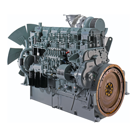
Chapter 1 GENERAL 1. External View Chapter 1 GENERAL S6R-PTA with fan spec Engine coolant outlet Thermostat case Tension pulley Water pump Damper Oil pan Note: Configuration varies depending on the destination and specifications. Engine Front View S6R-PTA with fan spec Timing gear case Rotation direction Rotation direction... - Page 19 Chapter 1 GENERAL S6R-PTA with fan spec Engine coolant outlet Fuel filter Oil cooler Fuel injection pump Breather Governor oil filter Front hanger Rear hanger Water pump Governor Engine coolant inlet Front Rear Fuel feed pump Damper Stop solenoid Oil filter Oil filler Bypass oil filter Fuel inlet...
- Page 20 Chapter 1 GENERAL S6R-PTK Engine coolant outlet Thermostat case Tension pulley Water pump Damper Oil pan Note: Configuration varies depending on the destination and specifications. Engine Front View S6R-PTK Timing gear case Rotation direction Rotation direction Rotation direction Flywheel Engine oil drain port Note: Configuration varies depending on the destination and specifications.
- Page 21 Chapter 1 GENERAL S6R-PTK Oil cooler Fuel filter Fuel injection pump Breather Governor oil filter Front hanger Rear hanger Water pump Governor Front Rear Damper Fuel feed pump Oil filter Stop solenoid Oil filler Bypass oil filter Oil level gauge Fuel inlet Fuel return port Note: Configuration varies depending on the destination and specifications.
- Page 22 Chapter 1 GENERAL S6R-Y2PTAW Engine coolant outlet Thermostat case Tension pulley Water pump Damper Water pump for air cooler cooling Oil pan Note: Configuration varies depending on the destination and specifications. Engine Front View S6R-Y2PTAW Timing gear case Flywheel Rotation direction Rotation direction Rotation direction Engine oil drain port...
- Page 23 Chapter 1 GENERAL S6R-Y2PTAW Oil cooler Fuel filter Fuel injection pump Breather Front hanger Rear hanger Water pump Governor Engine coolant inlet Front Rear Fuel feed pump Alternator Damper Stop solenoid Oil filter Oil filler Bypass oil filter Oil level gauge Fuel return port Fuel inlet Note: Configuration varies depending on the destination and specifications.
- Page 24 Chapter 1 GENERAL S6R2-PTAA Coolant outlet Air inlet for air cooler Air outlet for air cooler Thermostat case Water pump Damper Coolant inlet Note: Configuration varies depending on the destination and specifications. Engine Front View S6R2-PTAA Turbocharger Timing gear case Rotation direction Rotation direction Rotation direction...
- Page 25 Chapter 1 GENERAL S6R2-PTAA Exhaust pipe, exhaust outlet Breather Fuel filter Front hanger Oil cooler Stop lever Actuator (governor) Water pump Front Rear Fuel injection pump Damper Stop solenoid Fuel feed pump Oil filter Oil filler Fuel inlet Oil level gauge Bypass oil filter Fuel return port Note: Configuration varies depending on the destination and specifications.
- Page 26 Chapter 1 GENERAL S6R-Z3MPTAW Engine coolant outlet Thermostat case Tension pulley Water pump Damper Oil pan Note: Configuration varies depending on the destination and specifications. Engine Front View S6R-Z3MPTAW Silencer Timing gear case Rotation direction Rotation direction Rotation direction Flywheel Engine oil drain port Note: Configuration varies depending on the destination and specifications.
- Page 27 Chapter 1 GENERAL S6R-Z3MPTAW Fuel filter Oil cooler Fuel injection pump Breather Governor oil filter Front hanger Rear hanger Water pump Governor Engine coolant inlet Rear Front Fuel feed pump Damper Oil filler Note: Configuration varies Fuel return port depending on the destination Oil level gauge Fuel inlet and specifications.
-
Page 28: Outline Of Systems
Chapter 1 GENERAL 2. Outline of Systems 2.1 Outline of Fuel System Fuel leak-off pipe Fuel injection nozzle Fuel injection pump Fuel injection pipe Fuel filter Fuel feed pump From fuel tank To fuel tank Outline of Fuel System 2.2 Outline of Lubrication System Oil pressure governor spec Turbocharger Camshaft... -
Page 29: Outline Of Cooling System
Chapter 1 GENERAL Electronic governor spec Camshaft Turbocharger Rocker shaft Oil thermostat Piston Oil cooler Piston cooling nozzle Timing gear Water pump Fuel injection pump Oil pump Crankshaft Safety valve Relief valve Oil filter Bypass oil filter Oil strainer Oil filter Outline of Lubrication System 2.3 Outline of Cooling System PTA spec... - Page 30 Chapter 1 GENERAL PTK spec Air cooler, Water outlet pipe (rocker case) engine coolant outlet Thermostat Air cooler, Engine coolant inlet Water pump Oil cooler Air cooler Outline of Cooling System PTAW spec (Outside of water pump for air cooler cooling) Engine coolant outlet Water outlet pipe (rocker case) Exhaust manifold...
- Page 31 Chapter 1 GENERAL PTAW spec (Water pump for air cooler cooling mounted) Engine coolant Air cooler outlet coolant outlet Water outlet pipe (rocker case) Thermostat Air cooler Air cooler water pump Oil cooler Air cooler coolant outlet Engine coolant inlet Water pump Outline of Cooling System PTAA spec...
-
Page 32: Outline Of Inlet And Exhaust System
Chapter 1 GENERAL MTK, MPTK spec Water outlet pipe (rocker case) Exhaust manifold Thermostat Oil cooler Heat exchanger Sea water outlet port Marine gear oil cooler Sea water pump Sea water inlet port Water pump Outline of Cooling System 2.4 Outline of Inlet and Exhaust System Internal air cooler spec Charging air Exhaust air... - Page 33 Chapter 1 GENERAL External air cooler spec Charging air Exhaust air Exhaust outlet Turbocharger From air-cleaner Exhaust pipe Cylinder Air cooler Outline of Inlet and Exhaust System 1-18...
-
Page 34: Contents Of Plate And Label
Chapter 1 GENERAL 3. Contents of Plate and Label 3.1 Name Plate The name plate is attached on the lateral side of the engine, and shows the following information: Right side Engine serial number Manufactured date Total displacement Front Rear Engine output Rated speed Left side... -
Page 35: Specifications
Chapter 1 GENERAL 4. Specifications Engine model S6R2 Type Water cooled, four stroke cycle diesel, turbo charged No. of cylinders - Arrangement 6 cylinders, in-line Combustion system Direct injection system Valve mechanism Overhead Cylinder bore × stroke 170×180 mm [6.69×7.09 in.] 170×220 mm [6.69×8.66 in.] Total displacement 24.51 L [1495.9 cu in]... - Page 36 Chapter 1 GENERAL S6R2 Equipment name Specification name Overlap 61° Compression ratio 14 ○ ○ ○ ○ ○ ○ ○ ○ ○ ○ (37517-30101) Overlap 93° Compression ratio 15 ○ ○ ○ ○ ○ (37517-10401) Overlap 93° Compression ratio 14.5 ○...
- Page 37 Chapter 1 GENERAL S6R2 Equipment name Specification name TD10L-42F-34 ○ TD10L-42F-43 ○ ○ ○ ○ TD13L-47F-40 ○ ○ ○ ○ ○ ○ ○ TD13L-47F-47 ○ ○ ○ ○ ○ ○ ○ ○ TD13L-47F-55 ○ ○ TD13L-54QRC-47 ○ ○ TD13L-54QRC-47 ○ Water cool exhaust manifold TD13L-57V-55 ○...
- Page 38 Chapter 1 GENERAL S6R2 Equipment name Specification name Fresh water (internal cooling) air cool exhaust manifold ○ ○ ○ ○ ○ ○ ○ ○ ○ ○ (37555-30030) Fresh water (external cooling) ○ ○ ○ air cool exhaust manifold (37555-30040) Fresh water (internal cooling) Water cool exhaust manifold ○...
- Page 39 Chapter 1 GENERAL S6R2 Equipment name Specification name Diesel oil ○ ○ ○ ○ ○ ○ ○ ○ ○ ○ ○ ○ ○ ○ ○ Diesel oil, changover type ○ ○ ○ ○ ○ A diesel oil ○ ○ ○ ○...
- Page 40 Chapter 2 SERVICE DATA Maintenance Service Data ..................2-3 Maintenance Service Data of Engine General................2-3 Maintenance Service Data of Basic Engine................2-4 Maintenance Service Data of Fuel System................2-9 Maintenance Service Data of Lubrication System ..............2-11 Maintenance Service Data of Cooling System ............... 2-12 Maintenance Service Data of Electrical System ..............
-
Page 41: Maintenance Service Data
Chapter 2 SERVICE DATA 1. Maintenance Service Data Chapter 2 SERVICE DATA 1.1 Maintenance Service Data of Engine General Nominal Item Standard value Limit value Remarks value 1.8 MPa 1.27 MPa Cranking Compression pressure {18.5 kgf/cm {13 kgf/cm (approx 120 min [263 psi] [189 psi] 0.49 to 0.64 MPa... -
Page 42: Maintenance Service Data Of Basic Engine
Chapter 2 SERVICE DATA 1.2 Maintenance Service Data of Basic Engine Unit: mm [in.] Nominal Item Standard value Limit value Remarks value 36.000 to 36.040 36.090 Rocker bushing inside diameter ø36 [1.42] [1.4173 to 1.4189] [1.4209] Rockers 35.966 to 35.991 35.940 Rocker shaft outside diameter ø36 [1.42]... - Page 43 Chapter 2 SERVICE DATA Unit: mm [in.] Nominal Item Standard value Limit value Remarks value 0.07 Distortion of bottom surface 0.03 [0.0012] or less [0.003] Cylinder head 154.9 to 155.1 Height (reference) [6.098 to 6.106] ø170 170.02 to 170.04 P/N: 37507-22700 (S6R) [6.69] [6.6937 to 6.6945] 170.100...
-
Page 44: Overlap
Chapter 2 SERVICE DATA Unit: mm [in.] Nominal Item Standard value Limit value Remarks value 69.987 to 70.000 69.970 Piston pin Outside diameter ø70 [2.76] [2.7554 to 2.7559] [2.7547] 70.020 to 70.040 70.070 Inside diameter of connecting rod bushing ø70 [2.76] [2.7567 to 2.7575] [2.7587] 0.05/100 [0.0020/3.94]... - Page 45 Chapter 2 SERVICE DATA Unit: mm [in.] Nominal Item Standard value Limit value Remarks value 124.930 to 124.950 124.890 Standard [4.9185 to 4.9193] [4.9169] 124.680 to 124.700 124.640 0.25 [4.9084 to 4.9094] [4.9071] Crankpin outside ø125 124.430 to 124.450 124.390 0.50 diameter [4.92]...
- Page 46 Chapter 2 SERVICE DATA Unit: mm [in.] Nominal Item Standard value Limit value Remarks value 3.500 3.467 to 3.480 3.425 Standard [0.1378] [0.1365 to 0.1370] [0.1348] 3.625 3.592 to 3.605 3.550 0.25 [0.1427] [0.1414 to 0.1419] [0.1398] Main Thickness at 3.750 3.717 to 3.730 3.675...
-
Page 47: Maintenance Service Data Of Fuel System
Chapter 2 SERVICE DATA 1.3 Maintenance Service Data of Fuel System Unit: mm [in.] Item Nominal value Standard value Limit value Remarks P/N:37561-26400 [1.18] Free length of nozzle spring 26.8 P/N:48726-00402 [1.055] P/N:37561-26400 0.6 [0.0236] or less Squareness of nozzle spring P/N:48726-00402 1.25°or less... - Page 48 Chapter 2 SERVICE DATA Unit: mm [in.] Item Nominal value Standard value Limit value Remarks 89.987 to 90.022 ø90 [3.54] [3.5428 to 3.5442] Inside diameter of case bearing housing 99.987 to 100.022 ø100 [3.94] [3.9365 to 3.9379] 89.985 to 90.000 Small ø90 [3.54] [3.5427 to 3.5433]...
-
Page 49: Maintenance Service Data Of Lubrication System
Chapter 2 SERVICE DATA 1.4 Maintenance Service Data of Lubrication System Unit: mm [in.] Nominal Item Standard value Limit value Remarks value 0.087 to 0.316 0.500 Backlash between oil pump gear and idler gear [0.0034 to 0.0124] [0.0197] 0.100 to 0.200 0.400 Drive gear and driven gear backlash [0.0039 to 0.0079]... -
Page 50: Maintenance Service Data Of Cooling System
Chapter 2 SERVICE DATA 1.5 Maintenance Service Data of Cooling System Unit: mm [in.] Nominal Limit Item Standard value Remarks value value 51.970 to 52.000 Inside diameter of pulley bearing fit ø52 [2.05] [2.0461 to 2.0472] Outside 51.987 to 52.000 ø52 [2.05] diameter [2.0467 to 2.0472]... - Page 51 Chapter 2 SERVICE DATA Unit: mm [in.] Nominal Limit Item Standard value Remarks value value ø90 89.9825 to 90.0175 Inside diameter of case bearing housing [3.54] [3.5426 to 3.5440] Outside ø90 90.000 to 90.015 diameter [3.54] [3.5433 to 3.5439] ø30 29.990 to 30.000 Bearing [1.18 in.]...
-
Page 52: Maintenance Service Data Of Electrical System
Chapter 2 SERVICE DATA 1.6 Maintenance Service Data of Electrical System Unit: mm [in.] Nominal Item Standard value Limit value Remarks value ø43 [1.69] ø42 [1.65] Commu- Runout 0.06 [0.0024] 0.1 [0.004] tator 0.7 to 0.9 0.2 [0.008] or Undercut depth Armature [0.028 to 0.035] less... - Page 53 Chapter 2 SERVICE DATA Unit: mm [in.] Nominal Item Standard value Limit value Remarks value P/N: 0.127 [0.0050] 37566-30200 (Reference at Pressure 20°C [68°F]) P/N: 0.066 [0.0026] Coil 37566-45200 resistance P/N: (Ω) 0.92 [0.0362] 37566-30200 Magnetic (Reference at Holding switch 20°C [68°F]) P/N: 1.07 [0.0421]...
- Page 54 Chapter 2 SERVICE DATA Unit: mm [in.] Nominal Item Standard value Limit value Remarks value 30 A or more Rota- 2500 Output (when cold) tion current speed 35 A or more Initial (at 27 V) 5000 (min (when engine is hot) exciting P/N:04343-35500 type...
-
Page 55: Air Start System
Chapter 2 SERVICE DATA 1.6.1 Belt tension Unit N {kgf} [lbf] Belt straight distance (mm) [in.] Number Item 300 [11.81] more than 300 to 400 more than 400 to 500 more than 500 to 600 more than 600 of ribs or below [11.81 to 15.75] [15.75 to 19.69]... -
Page 56: Tightening Torque Table
Chapter 2 SERVICE DATA 2. Tightening Torque Table 2.1 Tightening Torque Spec for Basic Engine Tightening torque Dia x Pitch Description Remarks (M-thread) N·m kgf·m lbf·ft [Wet] 2-time tightening method, Cylinder head bolt M 22 × 2.5 539 ± 27 55 ±... -
Page 57: Tightening Torque Spec For Fuel System
Chapter 2 SERVICE DATA 2.2 Tightening Torque Spec for Fuel System Tightening torque ThreadsDia Description Remarks - Pitch (mm) N·m kgf·m lbf·ft Accessory drive case M 12 × 1.25 108 ± 5.4 11 ± 0.55 79.66 ± 3.98 Accessory M 30 × 1.5 490 ±... -
Page 58: Tightening Torque Spec For Cooling System
Chapter 2 SERVICE DATA 2.4 Tightening Torque Spec for Cooling System Tightening torque Dia x Pitch Description Remarks (M-thread) N·m kgf·m lbf·ft Pump M 12 × 1.25 59 ± 5.9 6 ± 0.6 43.52 ± 4.35 Water pump Pump shaft pulley (nut) M 24 ×... -
Page 59: Tightening Torque Spec For Electrical System
Chapter 2 SERVICE DATA 2.6 Tightening Torque Spec for Electrical System Tightening torque Dia x Pitch Description Remarks (M-thread) N·m kgf·m lbf·ft Starter - Install M 12 × 1.25 59 ± 5.9 6.0 ± 0.60 43.5 ± 4.35 Magnetic switch assembly M 6 ×... -
Page 60: Tightening Torque For Standard Bolts
Chapter 2 SERVICE DATA 2.8 Tightening Torque for Standard Bolts Width across Strength classification Thread size Threads flats Dia. x Pitch 10.9 (mm) N·m kgf·m lbf·ft N·m kgf·m lbf·ft M 8 × 1.25 12.5 22.1 M 10 × 1.25 24.3 44.3 M 12 ×... -
Page 61: Tightening Torque For Standard Eyebolts
Chapter 2 SERVICE DATA 2.9 Tightening Torque for Standard Eyebolts Strength classification Thread size Width across flats Dia. × Pitch (mm) [in.] (M-thread) N·m kgf·m lbf·ft 8 × 1.25 12 [0.47] 8 ± 1 0.8 ± 0.1 5.90 ± 0.73 10 ×... - Page 62 Chapter 3 SERVICE TOOLS Special Tools......................3-3...
-
Page 63: Special Tools
Chapter 3 SERVICE TOOLS 1. Special Tools Chapter 3 SERVICE TOOLS Maintenance Tool name Part No. Illustration Usage item Basic engine Rocker bushing tool 37591-02600 Rocker bushing - replace Bushing inside diam : ø36 × 40 mm [1.38 ×1.57 in.] Idler bushing puller 32591-02500 Idler bushing - replace... - Page 64 Chapter 3 SERVICE TOOLS Maintenance Tool name Part No. Illustration Usage item Basic engine Front slinger - insert 37591-03900 Front oil seal slinger installation Valve guide remover 33591-04300 Valve guide - remove ø17 × L100 Applicable valve guide inside/outside diam: ø10 × 18 mm [0.39 × 0.71 in.] ø10 ×...
- Page 65 Chapter 3 SERVICE TOOLS Maintenance Tool name Part No. Illustration Usage item Basic engine Cylinder liner remover 37591-04100 Cylinder liner - remove Applicable cylinder liner inner diam: ø170 mm [6.69 in.] Cam bushing tool 37591-08020 Cam bushing installation/removal assembly Jack bolt 64362-68500 Water pump plate - remove M12 ×...
- Page 66 Chapter 3 SERVICE TOOLS Maintenance Tool name Part No. Illustration Usage item Basic engine Projection plate 37598-09201 Depth of counterbore in crankcase - measure L230 × W50 × T15 mm [L9.06 × W1.97 × T0.59 in.] Bolt 37591-06300 Cylinder liner flange Protrusion - measure (Liner presser jig) M22 ×...
- Page 67 Chapter 3 SERVICE TOOLS Maintenance Tool name Part No. Illustration Usage item Cooling Impeller remover 37591-03200 Water pump impeller - pull-out system M18 × 1.5 mm Seal ring 45B91-02100 Water pump unit seal - install installer guide Mating ring 45B91-02200 Water pump mating ring - install installer guide Inspection and...
- Page 68 Chapter 4 OVERHAUL INSTRUCTIONS Determining Overhaul Timing ................4-3 Compression Pressure - Measure................4-4...
- Page 69 Chapter 4 OVERHAUL INSTRUCTIONS 1. Determining Overhaul Timing Chapter 4 OVERHAUL INSTRUCTIONS In most cases, the engine should be overhauled when the compression pressure of the engine decrease. An increase in engine oil consumption and blow-by gas should be considered when evaluating the engine condition. Such symptoms as the output decrease, fuel consumption increase, oil pressure decrease, engine starting difficulty and noise increase should be considered to evaluate overhaul timing, although these symptoms are often affected by various causes, and are not always effective to consider overhaul timing.
- Page 70 Chapter 4 OVERHAUL INSTRUCTIONS 2. Compression Pressure - Measure (a) Be sure to measure the compression pressure of all cylinders. It is not a clever way to measure Compression gauge P/N: 33A91-01700 the compression pressure of only two or three cylinders, and assume the compression pres- sure of all other cylinders.
- Page 71 Chapter 5 DISASSEMBLY OF BASIC ENGINE Cylinder Heads and Valve Mechanisms - Disassemble and Inspect ....5-3 Fuel Inlet Connector - Remove....................5-4 Nozzle Assembly - Remove...................... 5-4 Valve Clearance - Inspect......................5-4 Fuel Injection Timing - Inspect....................5-5 Rocker Shaft Assembly - Remove.................... 5-5 Clearance Between Bottom Face of Valve Bridge and Top Face of Valve Rotator - Inspect...
-
Page 72: Cylinder Heads And Valve Mechanisms - Disassemble And Inspect
Chapter 5 DISASSEMBLY OF BASIC ENGINE 1. Cylinder Heads and Valve Mechanisms - Disassemble and Inspect Chapter 5 DISASSEMBLY OF BASIC ENGINE Understanding of the current engine condition before disassembling is very important to know the cause of trouble and do the efficient work. -
Page 73: Fuel Inlet Connector - Remove
Chapter 5 DISASSEMBLY OF BASIC ENGINE 1.1 Fuel Inlet Connector - Remove Remove the fuel inlet connector. Fuel inlet connector Fuel Inlet Connector - Remove 1.2 Nozzle Assembly - Remove Nozzle remover P/N: 33591-10101 When removing the nozzle assembly with nozzle remover, be careful not to get caught your fingers Gasket between the nozzle remover weight, bar and plate. -
Page 74: Fuel Injection Timing - Inspect
Chapter 5 DISASSEMBLY OF BASIC ENGINE 1.4 Fuel Injection Timing - Inspect Inspect the fuel injection timing, and know the current con- dition. Pointer For the inspection procedures, refer to "Fuel Injection Tim- ing - Check and Adjust" of "ASSEMBLY OF BASIC Line mark on ENGINE. -
Page 75: Valve Bridge - Remove
Chapter 5 DISASSEMBLY OF BASIC ENGINE 1.7 Valve Bridge - Remove Remove the valve bridge and bridge cap. Note: Be careful not to drop the bridge cap into the cylinder Bridge cap Valve bridge head. Screw Valve Bridge - Remove 1.8 Rocker Case - Remove (1) Remove the snap ring of water outlet connector. -
Page 76: Valve And Valve Spring - Remove
Chapter 5 DISASSEMBLY OF BASIC ENGINE 1.11 Valve and Valve Spring - Remove Using a valve spring pusher, compress the valve spring evenly and remove the valve cotters. Valve spring pusher Note: If valves are reusable, mark each valve seat and the P/N:33591-04500 mating valve to identify their original positions. -
Page 77: Rear Mechanism - Disassemble And Inspect
Chapter 5 DISASSEMBLY OF BASIC ENGINE 2. Rear Mechanism - Disassemble and Inspect Understanding of the current engine condition before disassembling is very important to know the cause of trouble and do the efficient work. Depending on the maintenance work or purpose, it is desirable to inspect some of the following items before proceeding with any job. -
Page 78: Flywheel Face And Radial Runout - Measure
Chapter 5 DISASSEMBLY OF BASIC ENGINE 2.1 Flywheel Face and Radial Runout - Measure Measure the face and radial runouts of the flywheel, and know the current condition. For the measurement procedure, refer to "Flywheel Face Face runout measuring plane and Radial Runout - Measure"... -
Page 79: Timing Gear Backlash - Measure
Chapter 5 DISASSEMBLY OF BASIC ENGINE 2.4 Timing Gear Backlash - Measure Measure the timing gear backlash, and know the current condition. For the measurement procedure, refer to "Timing Gear Backlash - Measure" of "ASSEMBLY OF BASIC ENGINE." Timing Gear Backlash - Measure 2.5 Idler Gear End Play - Measure Measure the idler gear end play, and know the current con- dition. -
Page 80: Camshaft End Play - Measure
Chapter 5 DISASSEMBLY OF BASIC ENGINE 2.8 Camshaft End Play - Measure Measure the camshaft end play, and know the current condi- tion. For the measurement procedure, refer to "Camshaft End Play - Measure" of "ASSEMBLY OF BASIC ENGINE." Camshaft End Play - Measure 2.9 Camshaft Gear - Remove Remove the camshaft gear from the camshaft. -
Page 81: Rear Plate - Remove
Chapter 5 DISASSEMBLY OF BASIC ENGINE 2.12 Rear Plate - Remove (1) Remove the rear plate from the crankcase. (2) Remove the nozzle plate from the crankcase. Rear Plate - Remove 5-12... -
Page 82: Front Mechanism - Disassemble And Inspect
Chapter 5 DISASSEMBLY OF BASIC ENGINE 3. Front Mechanism - Disassemble and Inspect Understanding of the current engine condition before disassembling is very important to know the cause of trouble and do the efficient work. Depending on the maintenance work or purpose, it is desirable to inspect some of the following items before proceeding with any job. -
Page 83: Coupling - Remove
Chapter 5 DISASSEMBLY OF BASIC ENGINE 3.1 Coupling - Remove (With tachometer spec) (1) Remove the oil seal case and oil seal from the crank- case or fan drive case. Oil seal case Note: Replace the removed oil seal with a new one. Oil seal can not be re-used. -
Page 84: Front Pulley, Damper And Crankshaft Pulley - Remove
Chapter 5 DISASSEMBLY OF BASIC ENGINE 3.3 Front Pulley, Damper and Crankshaft Pulley - Remove Jack bolt Be careful not to drop or bump the damper. It can, (M10×1.25 mm) not only cause damage to parts, but also lead to per- sonnel injury. -
Page 85: Cylinder Liner, Piston And Connecting Rod - Disassemble And Inspect
Chapter 5 DISASSEMBLY OF BASIC ENGINE 4. Cylinder Liner, Piston and Connecting Rod - Disassemble and Inspect Understanding of the current engine condition before disassembling is very important to know the cause of trouble and do the efficient work. Depending on the maintenance work or purpose, it is desirable to inspect some of the following items before proceeding with any job. -
Page 86: Piston Protrusion - Measure
Chapter 5 DISASSEMBLY OF BASIC ENGINE 4.1 Piston Protrusion - Measure Measure the piston protrusion, and know the current condi- tion. Piston protrusion For the measurement procedure, refer to "Piston Protrusion - Measure" of "ASSEMBLY OF BASIC ENGINE." Piston Protrusion - Measure 4.2 Connecting Rod End Play - Measure Measure the connecting rod end play, and know the current condition. -
Page 87: Piston - Remove
Chapter 5 DISASSEMBLY OF BASIC ENGINE 4.5 Piston - Remove When holding the connecting rod with your hand to prevent it from swinging, be very careful, as you may suffer hand injuries from accidental movement of the connecting rod. (a) When pulling-out the piston, be careful not to drop the upper connecting rod bearing. (b) When removing piston, be careful not to damage cylinder liner by connecting rod runout. -
Page 88: Piston Ring - Remove
Chapter 5 DISASSEMBLY OF BASIC ENGINE 4.5.2 Removing the Piston With Pushing-up the Con- Eyebolt necting Rod Big End P/N:37591-02500 (1) Remove the connecting rod cap and rotate the crank- (M10×1.25 mm) shaft to bring the piston to the top dead center position. Piston &... -
Page 89: Cylinder Liner Inside Diameter - Measure
Chapter 5 DISASSEMBLY OF BASIC ENGINE 4.8 Cylinder Liner Inside Diameter - Measure Measure the cylinder liner inside diameter, and know the current condition. Cylinder liner Cylinder liner Cylinder liner For the measurement procedure, refer to "Cylinder Liner Inside Diameter - Measure" of "ASSEMBLY OF BASIC ENGINE."... -
Page 90: Crankcase, Crankshaft And Main Bearing - Disassemble And Inspect
Chapter 5 DISASSEMBLY OF BASIC ENGINE 5. Crankcase, Crankshaft and Main Bearing - Disassemble and Inspect Understanding of the current engine condition before disassembling is very important to know the cause of trouble and do the efficient work. Depending on the maintenance work or purpose, it is desirable to inspect some of the following items before proceeding with any job. -
Page 91: Crankcase - Turn Over (Upend)
Chapter 5 DISASSEMBLY OF BASIC ENGINE 5.1 Crankcase - Turn Over (Upend) Using a turnover machine, turn over the crankcase. When the turnover machine is not available, hitch slings to the Crankcase rotation direction crankcase using wood pieces and cloth pads, and raise the Crankcase crankcase with a hoist or crane. -
Page 92: Crankshaft - Remove
Chapter 5 DISASSEMBLY OF BASIC ENGINE 5.5 Crankshaft - Remove Crankshaft assembly (a) Before removing the crankshaft, remove the front side upper thrust plate first, and be careful not to drop it into crankcase. (b) When placing the crankshaft onto a pallet or other stands, be careful not to damage the crankshaft. - Page 93 Chapter 6 INSPECTION AND REPAIR OF BASIC ENGINE Cylinder Head and Valve Mechanism - Inspect and Repair......... 6-3 Bushing Inside Diameter and Shaft Outside Diameter of Rocker - Measure......6-3 Rocker Bushing - Replace ......................6-3 Valve Stem Outside Diameter and Valve Guide Inside Diameter - Measure ......6-4 Valve Guide - Replace......................
- Page 94 Chapter 6 INSPECTION AND REPAIR OF BASIC ENGINE Counterbore in Crankcase - Repair ..................6-26 Crankpin and Journal Outside Diameters - Measure.............. 6-27 Width of Crankpin and Rearmost Crank Main Journal - Measure .......... 6-28 Crankshaft Runout - Measure....................6-29 Crankshaft Gear - Inspect.......................
-
Page 95: Cylinder Head And Valve Mechanism - Inspect And Repair
Chapter 6 INSPECTION AND REPAIR OF BASIC ENGINE 1. Cylinder Head and Valve Mechanism - Inspect and Repair Chapter 6 I N SPECTI O N AND REPAI R OF BASI C ENGI N E 1.1 Bushing Inside Diameter and Shaft Outside Diameter of Rocker - Measure Measure the inside diameter of the rocker bushing and the Measurement Measurement direction... -
Page 96: Valve Stem Outside Diameter And Valve Guide Inside Diameter - Measure
Chapter 6 INSPECTION AND REPAIR OF BASIC ENGINE 1.3 Valve Stem Outside Diameter and Valve Guide Inside Diameter - Measure Measure the outside diameter of valve stem and the inside diameter of valve guide at the top and bottom sliding ends in Measurement direction right-angle directions as shown, as the sliding surface tends... -
Page 97: Valve Face - Inspect
Chapter 6 INSPECTION AND REPAIR OF BASIC ENGINE 1.5 Valve Face - Inspect Inspect the valve face after the valve guide is inspected or Seat width replaced. Lap the valve and valve seat whenever valve is refaced or replaced. Valve margin Valve sinkage Valve Face - Inspect 1.5.1 Valve Margin - Inspect... -
Page 98: Valve Seat - Reface
Chapter 6 INSPECTION AND REPAIR OF BASIC ENGINE 1.7 Valve Seat - Reface If any damage or inclusions are found, grind the sheet face. (1) Reface the valve seat with valve seat cutter or valve seat grinder. After refacing, insert sand paper of approx Socket 400 grit between cutter and valve, and glind valve seat (width across flats... - Page 99 Chapter 6 INSPECTION AND REPAIR OF BASIC ENGINE 1.8.3 Valve Seat - Install (1) Before installing the valve seat, measure the inside If the inside diameter of valve seat counterbore in cylin- diameter of valve seat counterbore in cylinder head and der head exceeds the limit, replace the cylinder head the outside diameter of valve seat to make sure that the with a new one.
-
Page 100: Valve And Valve Seat - Lap
Chapter 6 INSPECTION AND REPAIR OF BASIC ENGINE 1.9 Valve and Valve Seat - Lap Lap the valve and valve seat whenever valve seat is refaced or valve is replaced, or the contact surfaces fail to keep a pressure in the pressure test after assembling. (1) Apply a thin coat of lapping compound evenly to the valve face. -
Page 101: Squareness And Free Length Of Valve Spring - Measure
Chapter 6 INSPECTION AND REPAIR OF BASIC ENGINE 1.11 Squareness and Free Length of Valve Spring - Measure Measure the squareness and free length of valve spring. If the free length or squareness exceeds the limit, replace the Spring squareness valve spring with a new one. -
Page 102: Tappet - Inspect
Chapter 6 INSPECTION AND REPAIR OF BASIC ENGINE 1.12 Tappet - Inspect Inspect the tappet sliding face to cam for even wear. If the surface is defective, replace the tappet with a new one. Flaw, local wear Flaw, local wear Good Tappet Sliding Face to Cam - Inspect 1.13 Pushrod Runout - Measure... -
Page 103: Distortion Of Cylinder Head Bottom Surface - Measure
Chapter 6 INSPECTION AND REPAIR OF BASIC ENGINE 1.15 Distortion of Cylinder Head Bottom Surface - Measure Refacing depth of cylinder head is to be minimum. Excessive grinding of the cylinder head may result in defects such as contact between piston and valve. With a straight edge placed on the bottom face of cylinder head, measure the bottom face distortion with thickness gauges. -
Page 104: Rear Mechanism - Inspect And Repair
Chapter 6 INSPECTION AND REPAIR OF BASIC ENGINE 2. Rear Mechanism - Inspect and Repair 2.1 Idler Bushing Inside Diameter and Idler Shaft Outside Diameter - Measure Measure the idler bushing inside diameter and the idler shaft outside diameter. If the value exceeds the limit, replace the Measurement direction idler gear assembly or the idler shaft with a new one. -
Page 105: Cam Lift Of Cam Shaft Lobe - Measure
Chapter 6 INSPECTION AND REPAIR OF BASIC ENGINE 2.3 Cam Lift of Cam Shaft Lobe - Measure Measure the major diameter and minor diameter of cam lobe to know the cam lift. If the value exceeds the limit, replace the camshaft with a new one. Major axis Item Part No. -
Page 106: Camshaft Bushing - Inspect
Chapter 6 INSPECTION AND REPAIR OF BASIC ENGINE 2.6 Camshaft Bushing - Inspect (1) Check the inside surface of each bushing for damage, corrosion, flaking and other abnormalities. If any defect is found, replace the camshaft bushing with a new one. (2) Measure the camshaft bushing inside diameter with Measurement direction... - Page 107 Chapter 6 INSPECTION AND REPAIR OF BASIC ENGINE 2.7.2 Camshaft Bushing - Install Apply molybdenum-disulfide base anti-seizure Cam bushing (1) Insert the camshaft bushing installer into camshaft lubricant (ThreeBond 1910 or equivalent). sleeve bushing and install the cam bushing sleeve. Notch (2) Face the cut of the camshaft bushing upward and set the Cam bushing bolt...
-
Page 108: Front Mechanism - Inspect And Repair
Chapter 6 INSPECTION AND REPAIR OF BASIC ENGINE 3. Front Mechanism - Inspect and Repair 3.1 Damper - Inspect Visually Check the damper for cracks around outer periphery, swell- ing in end plate, silicone oil leakage, and discoloration and separation of coating due to overheating. If any defect is found, replace the damper with a new one. -
Page 109: Piston And Connecting Rod - Inspect And Repair
Chapter 6 INSPECTION AND REPAIR OF BASIC ENGINE 4. Piston and Connecting Rod - Inspect and Repair 4.1 Piston - Inspect Visually Check the combustion surface, piston pin bore, ring groove, sliding surface and bottom surface of piston. If any defect are found, replace the piston with a new one. -
Page 110: Piston Ring Groove - Inspect
Chapter 6 INSPECTION AND REPAIR OF BASIC ENGINE 4.4 Piston Ring Groove - Inspect Remove carbon deposits from piston and inspect the Ring insert entire circumference of piston. No. 1 compression ring (1) Remove all deposits such as carbon from each ring groove groove. -
Page 111: Piston Pin Outside Diameter - Measure
Chapter 6 INSPECTION AND REPAIR OF BASIC ENGINE 4.8 Piston Pin Outside Diameter - Measure Measure the piston pin outside diameter. Measurement If the value exceeds the limit, replace the piston pin with a direction new one. Nominal Item Standard value Limit value value Piston pin outside... -
Page 112: Connecting Rod Bushing - Replace
Chapter 6 INSPECTION AND REPAIR OF BASIC ENGINE 4.10 Connecting Rod Bushing - Replace Using the connecting rod bushing installer, replace the con- necting rod bushing. 4.10.1 Installer Base and Connecting Rod - Fix Base match mark Base match mark (1) Align the match mark on base with match mark on (red ø4 mm [0.16 in.]) (red line mark) - Page 113 Chapter 6 INSPECTION AND REPAIR OF BASIC ENGINE 4.10.3 Connecting Rod Bushing - Press-In (a) Make sure that the match marks (red lines) on col- Connecting rod bushing oil hole lars A and B are aligne. (b) Make sure that the oil hole of connecting rod Collar A bushing is in alignment with match mark (red φ4 match mark...
-
Page 114: Connecting Rod Assembly Weight Rank
Chapter 6 INSPECTION AND REPAIR OF BASIC ENGINE (4) Measure the inside diameter of the connecting rod 1.6S Bushing inner surface roughness bushing. If the value is out of the standard, ream the inside diam- Connecting rod bushing inside diameter eter to the standard. -
Page 115: Side Face Width Of Connecting Rod Big End - Measure
Chapter 6 INSPECTION AND REPAIR OF BASIC ENGINE 4.13 Side Face Width of Connecting Rod Big End - Measure (1) Inspect the side face of connecting rod big end visually. If there is any defect such as wear or flaw, replace the connecting rod with a new one. -
Page 116: Connecting Rod Bearing Thickness - Measure
Chapter 6 INSPECTION AND REPAIR OF BASIC ENGINE 4.16 Connecting Rod Bearing Thickness - Measure Measure the thickness of connecting rod at its center. If the value exceeds the limit, replace both upper and lower connecting rod bearing shells with new ones as a set. Measurement at the center When the crankshaft is re-ground due to wear of crank pin,... -
Page 117: Crankcase And Crankshaft - Inspect And Repair
Chapter 6 INSPECTION AND REPAIR OF BASIC ENGINE 5. Crankcase and Crankshaft - Inspect and Repair 5.1 Crankcase Top Surface Distortion - Measure Straight edge Refacing depth of crankcase is to be minimum. Excessive grinding of the crankcase may result in defects such as defective combustion and stamping between piston and valve. -
Page 118: Counterbore In Crankcase - Repair
Chapter 6 INSPECTION AND REPAIR OF BASIC ENGINE 5.4 Counterbore in Crankcase - Repair If local contact is shown on counterbore in crankcase, grind Grinder and repair. Grind the counterbore with crankcase grinder to correct the difference in depth at four directions in circum- ference to be less than 0.05 mm [0.0020 in.] After the grinding of counterbore in crankcase is completed, measure the cylinder liner flange protrusion. -
Page 119: Crankpin And Journal Outside Diameters - Measure
Chapter 6 INSPECTION AND REPAIR OF BASIC ENGINE 5.5 Crankpin and Journal Outside Diameters - Measure (1) Measure the outside diameter of crankpins and crank journals. If the value exceeds the limit, use an undersize bearing, and grind the crankshaft for use with undersized bear- ing. -
Page 120: Width Of Crankpin And Rearmost Crank Main Journal - Measure
Chapter 6 INSPECTION AND REPAIR OF BASIC ENGINE 5.6 Width of Crankpin and Rearmost Crank Main Journal - Measure (1) Inspect the ends of crankshaft for harmful flaw and wear. Crankpin width (2) Measure the crankpin and rearmost crank main journal Rearmost crank journal width width. -
Page 121: Crankshaft Runout - Measure
Chapter 6 INSPECTION AND REPAIR OF BASIC ENGINE 5.7 Crankshaft Runout - Measure Support the crankshaft at front and rear main journals with V-blocks, and measure the crankshaft runout at the center V-block main journal with dial gauge. If the runout deviates slightly from the standard, correct the crankshaft by grinding. -
Page 122: Oil Seal Slinger - Inspect
Chapter 6 INSPECTION AND REPAIR OF BASIC ENGINE 5.9.2 Crankshaft Gear - Install Aligning position (a) Check the correct installing direction and position of crankshaft gear. (b) To shrinkage-fit the crankshaft gear to crankshaft, heat the crankshaft gear evenly to the specified temperature. -
Page 123: Main Bearing - Inspect
Chapter 6 INSPECTION AND REPAIR OF BASIC ENGINE 5.11.2 Oil Seal Slinger - Install ID mark ID mark (1) Measure the outside diameter of crankshaft and inside (37111-14200) (37425-08201) diameter of oil seal slinger, and check the interference. 46.5 mm (2) Heat the oil seal slinger evenly to the temperature of [1.83 in.] 110ºC [230°F] or less. -
Page 124: Thickness Of Main Bearing Shell - Measure
Chapter 6 INSPECTION AND REPAIR OF BASIC ENGINE 5.13 Thickness of Main Bearing Shell - Measure Measure the thickness of main bearing shell at its center. If the value exceeds the limit, replace both upper and lower main bearing shells with new ones as a set. Measurement at the center When the crankshaft is re-griound due to wear of crank jou-... -
Page 125: Thickness Of Thrust Plate - Measure
Chapter 6 INSPECTION AND REPAIR OF BASIC ENGINE 5.15 Thickness of Thrust Plate - Measure Measure the thickness of thrust plate. If the value exceeds the limit, replace the thrust plate with a new one. When the crankshaft is re-ground due to wear, use the oversize thrust plate. - Page 126 Chapter 7 ASSEMBLY OF BASIC ENGINE Crankshaft and Main Bearing - Install ..............7-3 Crankcase - Turn Over (Upend) ....................7-3 Piston Cooling Nozzle - Install ....................7-3 Upper Main Bearing - Install ..................... 7-4 Rear Upper Thrust Plate - Install ....................7-4 Crankshaft - Install........................
- Page 127 Chapter 7 ASSEMBLY OF BASIC ENGINE 4.14 Flywheel Face and Radial Runout - Measure................. 7-25 4.15 Pickup - Install ........................7-25 Cylinder Head and Valve Mechanism - Assemble ..........7-26 Cylinder Head - Assemble ...................... 7-26 Valve Sinkage - Measure......................7-27 Tappet - Install ........................
-
Page 128: Crankshaft And Main Bearing - Install
Chapter 7 ASSEMBLY OF BASIC ENGINE 1. Crankshaft and Main Bearing - Install Chapter 7 ASSEMBLY OF BASIC ENGINE 1.1 Crankcase - Turn Over (Upend) Using a turnover machine, turn over the crankcase. When the turnover machine is not available, hitch slings to the Crankcase rotation direction crankcase using wood pieces and cloth pads, and raise the... -
Page 129: Upper Main Bearing - Install
Chapter 7 ASSEMBLY OF BASIC ENGINE 1.3 Upper Main Bearing - Install (a) Do not apply engine oil to the back face of the main bearing shell and main bearing fitting bore in the crank- case when installing the main bearing. Install the main bearing only after cleaning off foreign material, oil and grease from these surface using cleaning solvent. -
Page 130: Crankshaft - Install
Chapter 7 ASSEMBLY OF BASIC ENGINE 1.5 Crankshaft - Install (1) Make sure that the sliding surfaces of the upper main bearing shells installed in the crankcase are evenly Apply a small amount of engine oil to journal coated with clean engine oil. portion after cleaning. -
Page 131: Lower Main Bearing Shell And Lower Thrust Plate - Install
Chapter 7 ASSEMBLY OF BASIC ENGINE 1.7 Lower Main Bearing Shell and Lower Thrust Plate - Install (1) Install the lower main bearing shell, aligning the lug Lower main bearing with the lug slot in the main bearing cap. Note: Make the crush heights even. Lower thrust plate (2) Apply an even coat of clean engine oil to the sliding surfaces of lower main bearing shells. -
Page 132: Crankshaft End Play - Measure
Chapter 7 ASSEMBLY OF BASIC ENGINE 1.9 Crankshaft End Play - Measure (1) Verify the smooth rotation of the crankshaft. (2) Apply a dial gauge probe to the rear end face of crank- shaft. (3) Using a bar, move the crankshaft fully to the front and rear to read the each measurement. -
Page 133: Cylinder Liner, Piston And Connecting Rod - Assemble
Chapter 7 ASSEMBLY OF BASIC ENGINE 2. Cylinder Liner, Piston and Connecting Rod - Assemble 2.1 Cylinder Liner Protrusion - Measure (1) Place the dial gauge probe on the top surface of cylin- Hight of protrusion der liner flange, and adjust the dial gauge to zero. (2) Slide the probe to measure the protrusion of the cylin- der liner at four places. -
Page 134: Cylinder Liner - Install
Chapter 7 ASSEMBLY OF BASIC ENGINE (5) Calculate the cylinder liner flange protrusion by sub- tracting the depth of counterbore in crankcase from the Crankcase Shim thickness of the cylinder liner flange. Cylinder liner If the value exceeds the limit, insert a shim under the cylinder liner flange. -
Page 135: Cylinder Liner Flange Protrusion - Measure (When Cylinder Liner Installed)
Chapter 7 ASSEMBLY OF BASIC ENGINE 2.4 Cylinder Liner Flange Protrusion - Measure (When Cylinder Liner Installed) (1) Remove dust and dirt from the crankcase top face and Bolt Cylinder liner P/N:37591-06300 the cylinder liner top end face to measure. flange protrusion Tightening torque (2) Place the liner pusher on equally spaced 4 positions of... -
Page 136: Piston And Connecting Rod - Assemble
Chapter 7 ASSEMBLY OF BASIC ENGINE 2.6 Piston and Connecting Rod - Assemble (1) Apply engine oil to the piston pin, and assemble the View A piston and the connecting rod. The orientation of piston Piston weight and connecting rod is shown in the illustration. Note: The piston and piston pin are made for a clearance fit. -
Page 137: Crankshaft - Turn
Chapter 7 ASSEMBLY OF BASIC ENGINE 2.8 Crankshaft - Turn (1) Install two bolts to the flywheel mounting holes of the crankshaft. Crankshaft (2) Using the bolts, turn the crankshaft with a bar. M22 × 1.5 mm Crankshaft - Turn 2.9 Piston Installation - Prepare (1) Turn the crankshaft to a position where the connecting rod big end does not hit the crankpin on the piston... - Page 138 Chapter 7 ASSEMBLY OF BASIC ENGINE 2.11 Piston - Install When installing the piston, install the eye bolt to the Piston threaded hole on the piston top, and lift the piston with chain block. When the installation work is done by Camshaft side hand, be sure to take preventive measures so that pis- ton does not falling down, and be very careful not to...
-
Page 139: Piston- Install
Chapter 7 ASSEMBLY OF BASIC ENGINE (5) Install piston into cylinder liner by tapping the piston head with soft-head hammer. Note: Make sure that the piston is not caught in the cylinder Use of a soft hammer handle liner, or the connecting rod big end does not hit the crank pin. -
Page 140: Connecting Rod Cap - Install
Chapter 7 ASSEMBLY OF BASIC ENGINE 2.12 Connecting Rod Cap - Install Lower connecting rod Connecting rod bolt bearing (a) Make sure that the matching numbers on the con- Lug groove necting rod and the connecting rod cap are on the Threaded same side and in alignment. -
Page 141: Connecting Rod End Play - Measure
Chapter 7 ASSEMBLY OF BASIC ENGINE (6) Measure the connecting rod end play, and adjust the Tightening torque end play to the range of the standard value. Bolt ID mark "AL" and "AU": 637 ± 31.9 N·m {65 ± 3.25 kgf·m} (7) Tighten the connecting rod bolts to the specified torque. -
Page 142: Piston Protrusion - Measure
Chapter 7 ASSEMBLY OF BASIC ENGINE 2.14 Piston Protrusion - Measure Piston protrusion Piston protrusion must always meet the standard, as the amount of protrusion not only influences engine performance, but it also prevents valve from stamping. Measure the protrusion of each piston, following the instructions below. -
Page 143: Front Mechanism - Assemble
Chapter 7 ASSEMBLY OF BASIC ENGINE 3. Front Mechanism - Assemble 3.1 Front Cover - Install (1) Apply sealant (ThreeBond 1211) to the packing mount- ing surface of the crankcase, and install the packing. (2) Apply sealant (ThreeBond 1211) to the packing for Cutter front cover mounting surface, and install the front cover. -
Page 144: Crankshaft Pulley, Damper And Front Pulley - Install
Chapter 7 ASSEMBLY OF BASIC ENGINE 3.4 Crankshaft Pulley, Damper and Front Pulley - Install (1) Install the guide bolt to damper mounting thread on the crankshaft. (2) Put the crankshaft pulley, belt and damper to the guide 490 ± 24.5 N·m bolt, and install them aligning with the dowel pin. -
Page 145: Coupling - Install
Chapter 7 ASSEMBLY OF BASIC ENGINE 3.8 Coupling - Install (With tachometer spec) (1) Install the coupling aligning the dowel pin on the cam- shaft front end, and tighten the bolt. Coupling (2) Install the oil seal and O-ring to oil seal case, and Oil seal case tighten the bolt. -
Page 146: Rear Mechanism - Assemble
Chapter 7 ASSEMBLY OF BASIC ENGINE 4. Rear Mechanism - Assemble 4.1 Rear Plate - Install (1) Install the nozzle plates. (2) Apply sealant (ThreeBond 1211) to the rear plate pack- 108 ± 5.4 N·m {11 ± 0.55 kgf·m} ing mounting surface of the crankcase, and install the [80 ±... -
Page 147: Camshaft Gear - Install
Chapter 7 ASSEMBLY OF BASIC ENGINE 4.4 Camshaft Gear - Install (1) Install the camshaft gear by aligning its hole with the dowel pins on camshaft. Camshaft gear (2) Tighten the bolts to the specified torque. (3) Verify the camshaft smooth rotation. 176 ±... -
Page 148: Idler Gear - Install
Chapter 7 ASSEMBLY OF BASIC ENGINE 4.7 Idler Gear - Install (1) Turn the crankshaft to move the No. 1 cylinder to the top dead center. Camshaft gear (2) Apply engine oil to the idler shaft. Idler gear (3) Install the idler gear, aligning it with the match marks. (4) Install the thrust plate to the idler shaft. -
Page 149: Timing Gear Case - Install
Chapter 7 ASSEMBLY OF BASIC ENGINE 4.10 Timing Gear Case - Install Be careful not to drop or bump the timing gear case. It will result in personnel injury as well as damage of the timing gear case. (1) Apply sealant (ThreeBond 1211) to the rare plate pack- 255 ±... -
Page 150: Flywheel - Install
Chapter 7 ASSEMBLY OF BASIC ENGINE 4.12 Flywheel - Install Be careful not to drop or bump the flywheel. It will result in personnel injury as well as damage of the fly- wheel. (1) Check the mounting surfaces of flywheel and crank- shaft to make sure that they are free from any foreign 539 ±... -
Page 151: Cylinder Head And Valve Mechanism - Assemble
Chapter 7 ASSEMBLY OF BASIC ENGINE 5. Cylinder Head and Valve Mechanism - Assemble 5.1 Cylinder Head - Assemble Guide and seal installer Guide and seal installer P/N:37591-12300 P/N:37191-11500 (a) Be careful when inserting the valve through stem Valve stem seal, as the edge of stem can cause damage to Stem seal the stem seal lip. -
Page 152: Valve Sinkage - Measure
Chapter 7 ASSEMBLY OF BASIC ENGINE 5.2 Valve Sinkage - Measure Measure the valve sinkage. Seat width If the value exceeds the limit, replace the valve or valve seat with a new one. Lap the valve and valve seat whenever valve or valve seat is refaced or replaced. -
Page 153: Cylinder Head Gasket - Install
Chapter 7 ASSEMBLY OF BASIC ENGINE 5.5 Cylinder Head Gasket - Install (1) Wipe off oil, grease and other contamination from the cylinder head bottom surface and crankcase top sur- face. (2) Install the cylinder head gasket coated with liquid gas- ket onto crankcase with dowel pin and hole in align- ment. -
Page 154: Rocker Case - Install
Chapter 7 ASSEMBLY OF BASIC ENGINE 5.8 Rocker Case - Install (1) Install O-rings on water outlet connector. Apply grease Connector Connector to the O-ring sliding surface. mounting mounting Snap ring groove hole (2) Apply grease to connector mounting hole of rocker hole (deep side) case. -
Page 155: Clearance Between Bottom Face Of Valve Bridge And Top Face Of Valve Rotator - Inspect
Chapter 7 ASSEMBLY OF BASIC ENGINE 5.11 Clearance Between Bottom Face of Valve Bridge and Top Face of Valve Rotator - Inspect Hold down the top of bridge by hand. Be sure to keep the standard clearance between Valve bridge Bridge cap valve bridge and valve rotator. -
Page 156: Valve Clearance - Check And Adjust
Chapter 7 ASSEMBLY OF BASIC ENGINE 5.13 Valve Clearance - Check and Adjust Adjust the valve clearance when the engine is cold. Note:(a) The inlet valves are on the left side and exhaust valves are on the right when the cylinder head is viewed from camshaft side. - Page 157 Chapter 7 ASSEMBLY OF BASIC ENGINE 5.14.2 Fuel Injection Timing - Check (1) Turn the crankshaft in normal direction, and stop the turning when the No. 1 cylinder is positioned at approx 10° before the specified fuel injection timing. Check that the "0" stamped line of fuel injection pump flywheel indicates before the pointer.
-
Page 158: Valve Timing - Inspect
Chapter 7 ASSEMBLY OF BASIC ENGINE 5.15 Valve Timing - Inspect The specified valve timing is automatically made, when gears are assembled by aligning match marks and valve clearance is adjusted to the specified value. To make sure, check the valve timing as follows: 5.15.1 Valve Timing at Normal Valve Clearance (No Rocker arm Thickness Gauge Insertion) - Page 159 Chapter 7 ASSEMBLY OF BASIC ENGINE Overlap 61° spec 10.5° 24° 37° Exhaust valve closed Inlet valve open 2.5° Exhaust valve closed Inlet valve open Rotation direction Rotation direction Exhaust valve open Exhaust valve open 57° Inlet valve closed 44° 26°...
-
Page 160: Fuel Injection Nozzle Assembly - Install
Chapter 7 ASSEMBLY OF BASIC ENGINE Overlap 93° advanced by 4° spec 18° 36° 57° Exhaust valve closed Inlet valve open Exhaust valve closed 3° Inlet valve open Rotation direction Rotation direction Exhaust valve open 61° 8.5° 29.5° 40° Inlet valve closed Inlet valve closed Exhaust valve open Overlap 93°... - Page 161 Chapter 8 FUEL SYSTEM Fuel System - Remove and Inspect ............... 8-3 Fuel Injection Pipe and Fuel Leak-off Pipe - Remove and Inspect........... 8-3 Fuel Filter and Fuel Pipe - Remove and Inspect ..............8-7 Stop Solenoid - Remove and Inspect ..................8-9 Fuel Control Link - Remove and Inspect ................
-
Page 162: Fuel System - Remove And Inspect
Chapter 8 FUEL SYSTEM 1. Fuel System - Remove and Inspect Chapter 8 FUEL SYSTEM 1.1 Fuel Injection Pipe and Fuel Leak-off Pipe - Remove and Inspect Standard injection pipe spec 1 No.2 cylinder head Leak, crack, contact Replace Replace Replace Replace Replace... - Page 163 Chapter 8 FUEL SYSTEM Standard injection pipe spec 2 No.2 cylinder head Leak, crack, contact Replace Replace Replace Replace Replace Replace Fuel Injection Pipe and Fuel Leak-off Pipe - Remove and Inspect Removing Sequence 1 Clamp 4 Leak-off pipe 2 No.1 to 6 fuel injection pipe 5 Leak-off end pipe 3 Leak-off pipe 6 Leak-off pipe...
- Page 164 Chapter 8 FUEL SYSTEM Double layer injection pipe spec 1 No.2 cylinder head Replace Replace Replace Replace To oil leak sensor Replace Replace Fuel Injection Pipe and Fuel Leak-off Pipe - Remove and Inspect Removing Sequence 1 Leak-off pipe 5 Leak-off pipe 2 Leak connector 6 Leak-off pipe 3 Clamp...
- Page 165 Chapter 8 FUEL SYSTEM Double layer injection pipe spec 2 No.2 cylinder head Leak, crack, contact Replace Replace Replace Replace To oil leak sensor Replace Replace Fuel Injection Pipe and Fuel Leak-off Pipe - Remove and Inspect Removing Sequence 1 Leak-off pipe 5 Leak-off pipe 2 Leak connector 6 Leak-off pipe...
-
Page 166: Fuel Filter And Fuel Pipe - Remove And Inspect
Chapter 8 FUEL SYSTEM 1.2 Fuel Filter and Fuel Pipe - Remove and Inspect Fuel oil A spec Diesel oil spec Replace Replace With primary filter attachment spec Replace Replace Replace Replace Fuel Filter and Fuel Pipe - Remove and Inspect Removing Sequence 1 Fuel pipe 4 Bracket... - Page 167 Chapter 8 FUEL SYSTEM Changeover filter spec Replace Replace Replace Fuel oil A spec Diesel oil spec Replace Fuel Filter and Fuel Pipe - Remove and Inspect Removing Sequence 1 Fuel pipe 3 Fuel filter 4 Bracket 2 Fuel pipe Note: The consisting parts at fuel inlet and outlet differ depending on the customization and specification.
-
Page 168: Stop Solenoid - Remove And Inspect
Chapter 8 FUEL SYSTEM 1.3 Stop Solenoid - Remove and Inspect Stop solenoid RUN OFF spec Oil cooler cover Stop Solenoid - Remove and Inspect Removing Sequence 1 Link 4 Ball bearing 7 Stop solenoid 2 End plate 5 Stop lever 8 Bracket 3 Snap ring 6 Follower... - Page 169 Chapter 8 FUEL SYSTEM Stop solenoid RUN ON spec Oil cooler cover Replace: Rubber cushion Side cover Replace: Rubber cushion Stop Solenoid - Remove and Inspect Removing Sequence 1 Link 4 Ball bearing 7 Stop solenoid 2 End plate 5 Stop lever 8 Bracket 3 Snap ring 6 Follower...
- Page 170 Chapter 8 FUEL SYSTEM Starting rack limit solenoid spec Oil cooler cover Stop Solenoid - Remove and Inspect Removing Sequence 1 Link 5 Ball bearing 9 Start rack restrict solenoid 2 Link 6 Stop lever 10 Bracket 3 End plate 7 Follower 4 Snap ring 8 Stop solenoid...
-
Page 171: Fuel Control Link - Remove And Inspect
Chapter 8 FUEL SYSTEM 1.4 Fuel Control Link - Remove and Inspect Oil pressure governor spec Looseness, wear Deterioration, deformation Looseness, wear *Wodward PSG governor Fuel Control Link - Remove and Inspect Removing Sequence 1 Link 3 Link 5 Lever 2 Governor lever 4 Stop lever 8-12... - Page 172 Chapter 8 FUEL SYSTEM Oil pressure governor spec Looseness, wear Wear, rotation Deterioration, deformation Looseness, wear *Woodward EP-3P governor Fuel Control Link - Remove and Inspect Removing Sequence 1 Link 3 Link 5 Lever 2 Governor lever 4 Stop lever 8-13...
- Page 173 Chapter 8 FUEL SYSTEM Actuator spec Looseness, wear DYNA 8000 SG4017 Wear, rotation Looseness, wear *Toho Seisakusho SG4017 actuator, Woodward DYNA 8000 actuator Fuel Control Link - Remove and Inspect Removing Sequence 1 Link 3 Link 4 Stop lever 2 Governor lever 8-14...
- Page 174 Chapter 8 FUEL SYSTEM Actuator spec Looseness, wear Wear, rotation Deterioration, deformation Wear, rotation Looseness, wear *Woodward ProAct actuator Fuel Control Link - Remove and Inspect Removing Sequence 1 Link 3 Link 5 Lever 2 Governor lever 4 Stop lever 8-15...
-
Page 175: Governor And Actuator - Remove And Inspect
Chapter 8 FUEL SYSTEM 1.5 Governor and Actuator - Remove and Inspect Oil pressure governor, actuator spec Oil pressure governor, actuator spec c. SG4017 c. SG4017 d. DYNA 8000 d. DYNA 8000 a. PSG a. PSG Replace Replace b. EG-3P b. - Page 176 Chapter 8 FUEL SYSTEM Actuator spec Replace: Rubber cushion Replace Replace: Rubber cushion *Woodward ProAct actuator Actuator - Remove and Inspect Removing Sequence 1 Actuator 2 Plate 3 Actuator bracket 8-17...
-
Page 177: Fuel Injection Pump - Remove And Inspect
Chapter 8 FUEL SYSTEM 1.6 Fuel Injection Pump - Remove and Inspect MTK2, MTK3 spec Fuel Injection Pump - Remove and Inspect Removing Sequence 1 Coupling cover 4 Fuel injection pump (Approx 56 kg [123 lb]) 2 Bracket 5 Bracket 3 Bracket 8-18... -
Page 178: Fuel System - Disassemble, Inspect And Assemble
Chapter 8 FUEL SYSTEM 2. Fuel System - Disassemble, Inspect and Assemble 2.1 Fuel Filter (Paper Element) - Disassemble, Inspect and Assemble Air vent plug 9 ± 1 N·m {0.9 ± 0.1 kgf·m} [6.6 ±0.7 lbf·ft] Replace Crack, flaw Fuel filter bracket Filter wrench Fuel filter cartridge Use the filter wrench to remove... - Page 179 Chapter 8 FUEL SYSTEM Change over type fuel filter spec Air vent plug Replace 9 ± 1 N·m {0.9 ± 0.1 kgf·m} [6.6 ±0.7 lbf·ft] Filter wrench Crack, flaw Use the filter wrench to remove the fuel filter. (Use only when removing) Replace Dent Fuel Filter (Paper Element) - Disassemble, Inspect and Assemble...
- Page 180 Chapter 8 FUEL SYSTEM Wire element spec Replace Replace Replace Crack, threaded portion, flaw 20 N·m {2.0 kgf·m} Replace [15 lbf · Replace Fuel Filter (Wire Element) - Disassemble, Inspect and Assemble Disassembling Sequence 1 Plug, packing 6 Element 2 Bolt, spring washer, plain washer 7 Rod, O-ring 3 Flange, lower case, packing 8 Snap ring, washer, handle...
- Page 181 Chapter 8 FUEL SYSTEM 2.1.1 Fuel Filter Cartridge - Install (a) Make sure that there is no flame around the area before handling fuel. (b) Wipe any spilled fuel to prevent a fire. (c) Do not use the fuel filter cartridge that has a dent on the case. If the case has a dented, it can cause damage to the fuel filter cartridge, leading to fuel leaks during operation, and results in a fire.
-
Page 182: Fuel Injection Nozzle - Disassemble And Inspect
Chapter 8 FUEL SYSTEM 2.2 Fuel Injection Nozzle - Disassemble and Inspect Understanding of the current engine condition before disassembling is very important to know the cause of trouble and do the efficient work. Depending on the maintenance work or purpose, it is desirable to inspect some of the following items before proceeding with any job. - Page 183 Chapter 8 FUEL SYSTEM Shim adjust type spec Replace Replace Fatigue, damage Wear of needle valve and contact surface Carbon deposit Nozzle hole clogged, needle valve fixing Replace Fuel Injection Nozzle - Disassemble and Inspect Disassembling Sequence 1 Short plug 6 Push rod, nozzle spring 2 O-ring 7 Shim...
-
Page 184: Fuel Injection Nozzle - Inspect And Adjust
Chapter 8 FUEL SYSTEM 2.3 Fuel Injection Nozzle - Inspect and Adjust 2.3.1 Fuel Injection Start Pressure - Inspect and Adjust Nozzle tester Never touch the fuel injection nozzle orifice during P/N:83091-03301 nozzle injection test. (Screw adjust type) (1) Install the fuel injection nozzle to the nozzle tester. (2) Push down the handle at a speed of one stroke a second and measure the pressure when injection starts. - Page 185 Chapter 8 FUEL SYSTEM (Shim adjust type) (1) Install the fuel injection nozzle to the nozzle tester. (2) Push down the handle at a speed of one stroke a second and measure the pressure when injection starts. If the pressure is out of the standard, adjust it to the standard. (3) Adjust the injection start pressure by increasing or decreasing the number of shims.
- Page 186 Chapter 8 FUEL SYSTEM 2.3.2 Fuel Injection Nozzle Spray - Inspect When adjusting the nozzle opening pressure with the nozzle tester, inspect for nozzle orifice clogging, fuel spray pattern Good Faulty spray and dripping. If spray condition is faulty, clean or replace the nozzle tip.
- Page 187 Chapter 8 FUEL SYSTEM 2.3.4 Squareness, Free Length of Nozzle Spring, Parallelism of Top and Bottom Faces - Measure Squareness Measure the squareness, free length and parallelism of top and bottom surfaces of nozzle spring. Square Item Spring part No. Standard value 37561-26400 30 mm [1.18 in.]...
-
Page 188: Fuel Injection Nozzle - Assemble
Chapter 8 FUEL SYSTEM 2.4 Fuel Injection Nozzle - Assemble Screw adjustment TE type spec 39 ± 5 N·m Do not hit with a hammer, etc. {4 ± 0.5 kgf·m} when installing into cylinder head. [29 ± 3.7 lbf·ft] 73.5 ± 4.5 N·m Apply engine oil to both sides {7.5 ±... - Page 189 Chapter 8 FUEL SYSTEM Screw adjustment T type spec 39 ± 5 N·m Do not hit with a hammer, etc. {4 ± 0.5 kgf·m} when installing into cylinder head. [29 ± 3.7 lbf·ft] 73.5 ± 4.5 N·m Apply engine oil to both sides {7.5 ±...
- Page 190 Chapter 8 FUEL SYSTEM Screw adjustment S type spec 39 ± 5 N·m Do not hit with a hammer, etc. {4 ± 0.5 kgf·m} when installing into cylinder head. [29 ± 3.7 lbf·ft] 73.5 ± 4.5 N·m Apply engine oil to both sides of sealing washer.
- Page 191 Chapter 8 FUEL SYSTEM Shim adjustment T type spec Do not hit with a hammer, etc. when installing into cylinder head. 73.5 ± 4.5 N·m {7.5 ± 0.5 kgf·m} [54 ± 3.3 lbf·ft] Retaining nut 186.5 ± 9.5 N·m Nozzle tip is the same as {19 ±...
-
Page 192: Fuel Injection Pump Accessory Drive - Disassemble And Inspect
Chapter 8 FUEL SYSTEM 2.5 Fuel Injection Pump Accessory Drive - Disassemble and Inspect Deformation, lip surface wear Wear, flaw Rotation Wear, flaw Rotation Peeling, wear Fuel Injection Pump Accessory Drive - Disassemble and Inspect Disassembling Sequence 1 Nut 4 Snap ring 7 Bearing 2 Washer 5 Drive shaft... -
Page 193: Outside Diameter And Inside Diameter Of Accessory Drive Bearing Fit - Inspect
Chapter 8 FUEL SYSTEM 2.6 Outside Diameter and Inside Diameter of Accessory Drive Bearing Fit - Inspect (1) Rotate the bearing and if the rotation is not smooth, replace the bearing with a new one. Fuel injection pump gear (2) Inspect the fit of drive shaft and bearing. If significant wear is found, replace them with new ones. -
Page 194: Fuel Injection Pump Accessory Drive - Assemble
Chapter 8 FUEL SYSTEM 2.7 Fuel Injection Pump Accessory Drive - Assemble 490 ± 24.5 N·m {50 ± 2.5 kgf·m} [361 ± 18.1 lbf·ft] Apply engine oil to lip portion. Application of engine oil Fuel Injection Pump Accessory Drive - Assemble 8-35... -
Page 195: Governor Drive - Disassemble And Inspect
Chapter 8 FUEL SYSTEM 2.8 Governor Drive - Disassemble and Inspect Oil pressure governor spec Flaw, wear Wear Rotation Flaw, wear Number of teeth: 12 Rotation Number of teeth: 15 Spline defect, wear PSG governor PSG, EG-3P governor MAX 1450 rpm spec 1460 rpm or faster spec *Woodward PSG governor, EG-3P governor Replace... -
Page 196: Outside Diameter And Inside Diameter Of Bearing Fit
Chapter 8 FUEL SYSTEM 2.9 Outside Diameter and Inside Diameter of Bearing Fit (Oil pressure governor spec) Rotate the bearing and if the rotation is not smooth, replace the bearing with a new one. Inspect the fit of drive shaft, idler shaft and bearing. If significant wear is found, replace them with new ones. Inspect the fit of drive case and bearing. -
Page 197: Governor Drive - Assemble
Chapter 8 FUEL SYSTEM 2.10 Governor Drive - Assemble Oil pressure governor spec Shrink fit (200°C [392°F] or below) Backlash 0.12 to 0.18 mm [0.0047 to 0.0071 in.] Shrink fit (200°C [392°F] or below) 108 ± 5.4 N·m {11 ± 0.55 kgf·m} [80 ±... -
Page 198: Fuel System - Install
Chapter 8 FUEL SYSTEM 3. Fuel System - Install Install the parts in the reverse order of the disassemble sequence. (Refer to the illustration for disassembling.) Clean and dry well the fuel passage. 3.1 Fuel Injection Pump - Install 108 ± 5.4 N·m {11 ±... - Page 199 Chapter 8 FUEL SYSTEM 3.1.1 Checking Before Installing Fuel Injection Pump Pointer Flywheel zero line Ensure the correct mounting position of drive coupling. mark position If it is installed 180 degrees out of position, the fuel injection timing cannot be adjusted. (1) Rotate the crankshaft to the No.
- Page 200 Chapter 8 FUEL SYSTEM 3.1.2 Fuel Injection Pump - Install (a) First, tighten the bolts (long) to connect the drive coupling and laminated plates to the specified torque, and then loosen the bolts. Tighten again to the specified torque. (2-time tightening) (b) Wash the bolt, bushing and washer before using.
- Page 201 Chapter 8 FUEL SYSTEM 3.1.3 Clearance Between Fuel Injection Pump Clearance Flywheel and Drive Coupling - Adjust 59 ± 0.25 mm 172 ± 5 N·m [2.32 ± 0.0098 in.] {17.5 ± 0.5 kgf·m} Adjust the clearance between the fuel injection pump fly- [127 ±...
-
Page 202: Fuel Control Link - Install
Chapter 8 FUEL SYSTEM 3.2 Fuel Control Link - Install 3.2.1 Control Link Lever - Install (1) Install the link lever with ball bearing, snap ring and end plate to the bracket. (2) Set the governor output shaft at "0" angle (fuel decreasing side) and the specified angle of governor lever, then engage the serrated portion of the shaft. -
Page 203: Stop Solenoid - Install
Chapter 8 FUEL SYSTEM (1) Adjust the link between the fuel injection pump rack and rack control lever to 65 ± 0.7 mm [2.56 ± 0.028 in.], and install the fuel control link. (2) Install the control link between the rack control lever and governor lever. (3) Adjust the length of control link so that the distance between the end face of fuel injection pump and the end of rack becomes 68±0.5mm [2.67±0.02 in.]. - Page 204 Chapter 8 FUEL SYSTEM 3.3.2 Stop Solenoid (RUN OFF) - Adjust Clearance: 0 mm (contact) Stop lever Left-hand thread Variable length control link Make screw engagement Stop solenoid OFF: margin even. 68 ± 0.5 mm [2.68 ± 0.02 in.] Right-hand Play: approx.
- Page 205 Chapter 8 FUEL SYSTEM 3.3.3 Stop Solenoid (RUN OFF), Start Rack Restrict Solenoid (RUN OFF) - Adjust Clearance: 0 mm (contact) Left-hand Stop lever thread Make screw Variable length control link engagement Stop solenoid OFF: margin even. 68 ± 0.5 mm [2.68 ± 0.02 in.] Play: approx.
- Page 206 Chapter 8 FUEL SYSTEM 3.3.4 Solenoid Function - Verify Make sure the solenoid functions of start, running and emergency stop of the engine and check the fuel injection pump rack positions. Stop solenoid Specification Item Engine starting Engine running Engine emergency stop Plunger position (spring condition) Compressed Stretched...
- Page 207 Chapter 9 LUBRICATION SYSTEM Lubrication System - Remove and Inspect ............9-3 Lubrication System - Remove and Inspect (1)................9-3 Lubrication System - Remove and Inspect (2)................9-4 Lubrication System - Remove and Inspect (3)................9-5 Governor Oil Filter - Remove and Inspect ................9-6 Lubrication System - Disassemble, Inspect and Assemble ........
-
Page 208: Lubrication System - Remove And Inspect
Chapter 9 LUBRICATION SYSTEM 1. Lubrication System - Remove and Inspect Chapter 9 LUBRICATION SYSTEM 1.1 Lubrication System - Remove and Inspect (1) Replace Replace Rear Replace Replace Replace Replace Replace Replace Replace Replace Lubrication System - Remove and Inspect (1) Removing Sequence 1 Oil pipe 4 Oil pipe... -
Page 209: Lubrication System - Remove And Inspect (2)
Chapter 9 LUBRICATION SYSTEM 1.2 Lubrication System - Remove and Inspect (2) Replace Replace Left side oil filter spec Front Replace Right side oil filter spec Replace Left side oil filter spec Rear Right side oil filter spec Replace (Changeover-type oil filter) Replace Replace Replace... - Page 210 Chapter 9 LUBRICATION SYSTEM 1.3 Lubrication System - Remove and Inspect (3) Replace Replace Clogging, crack with emergncy oil strainer spec Deep oil pan spec Replace Replace Crack Replace Lubrication System - Remove and Inspect (3) Removing Sequence 1 Oil level gauge 5 Oil pipe 2 Oil pan (Standard: approx 55 kg [121 lb] 6 Oil pump...
-
Page 211: Governor Oil Filter - Remove And Inspect
Chapter 9 LUBRICATION SYSTEM 1.4 Governor Oil Filter - Remove and Inspect Oil pressure governor spec Replace Replace Replace Replace EG3P governor spec Replace To crankcase Replace Governor Replace To crankcase Timing gear case Timing gear case *Woodward EG-3P governor Governor Oil Filter - Remove and Inspect Removing Sequence 1 Oil pipe... -
Page 212: Lubrication System - Disassemble, Inspect And Assemble
Chapter 9 LUBRICATION SYSTEM 2. Lubrication System - Disassemble, Inspect and Assemble 2.1 Oil Pump and Safety Valve - Disassemble and Inspect Gear defect, wear Crack, flaw Wear Wear Wear Crack, flaw Gear defect, wear Spring settling, break, wear Oil Pump and Safety Valve - Disassemble and Inspect Disassembling Sequence 1 Safety valve 4 Oil pump gear... -
Page 213: Oil Pump And Safety Valve - Inspect
Chapter 9 LUBRICATION SYSTEM 2.2 Oil Pump and Safety Valve - Inspect 2.2.1 Backlash Between Oil Pump Gear and Idler Gear - Measure Measure the backlash between oil pump gear and idler gear. If the value exceeds the limit, replace the gears with new ones. - Page 214 Chapter 9 LUBRICATION SYSTEM 2.2.5 Drive/Driven Gear Shaft Outside Diameters and Bushing Inside Diameters - Measure (1) Check the gear teeth. If any defect is found, replace the gear with a new one. (2) Measure the drive/driven gear shaft outside diameters and bushing inside diameters.
-
Page 215: Oil Pump And Safety Valve - Assemble
Chapter 9 LUBRICATION SYSTEM 2.3 Oil Pump and Safety Valve - Assemble 69 ± 3.5 N·m {7 ± 0.35 kgf·m} [50.9 ± 2.58 lbf·ft] Wipe grease from nut and spindle, and apply Locktite 262 to threads before tightening. Backlash 0.087 to 0.316 mm [0.0034 to 0.0124 in.] Spindle 33 ±... -
Page 216: Relief Valve - Disassemble And Inspect
Chapter 9 LUBRICATION SYSTEM 2.4 Relief Valve - Disassemble and Inspect Left oil filter spec Settling Right oil filter spec Relief Valve - Disassemble and Inspect Disassembling Sequence 1 Stopper 3 Relief valve 5 Plate 2 Spring 4 Sleeve 9-11... -
Page 217: Relief Valve - Inspect
Chapter 9 LUBRICATION SYSTEM 2.5 Relief Valve - Inspect (1) Inspect the relief valve spring, and if any deformation, wear or damage is found, replace the spring with a new one. Item Standard value Relief valve 115 mm [4.53 in.] Spring free length (2) Inspect the valve, and if any wear, scratch, or slide mal- functions are found, replace the valve with a new one. -
Page 218: Oil Cooler And Oil Thermostat - Disassemble
Chapter 9 LUBRICATION SYSTEM 2.7 Oil Cooler and Oil Thermostat - Disassemble Replace Replace Clogging, flaw, crack Replace Replace Oil Cooler and Oil Thermostat - Disassemble Disassembling Sequence 1 Nut 4 Element 6 Sealing 2 Oil cooler cover 5 Oil thermostat 7 Plug 3 Packing Replace packings and O-rings with new ones when assembling. -
Page 219: Oil Thermostat - Inspect
Chapter 9 LUBRICATION SYSTEM 2.7.1 Oil Cooler - Inspect Check the oil passages of element for flaws or cracks by Leak, flaw, crack applying compressed air of 1.5 MPa {15 kgf/cm } [217 psi]. If any leakage or damage is found, replace the element with a new one. -
Page 220: Oil Filter - Disassemble And Inspect
Chapter 9 LUBRICATION SYSTEM 2.10 Oil Filter - Disassemble and Inspect Replace Replace Clogging, crack, deformation Oil Filter - Disassemble and Inspect Disassembling Sequence 1 Oil filter 3 Oil filter alarm 2 Bypass oil filter 4 Bracket 9-15... - Page 221 Chapter 9 LUBRICATION SYSTEM Right oil filter spec (Changeover-type oil filter) Replace Replace Replace Replace Bypass filter Oil filter Oil Filter - Disassemble and Inspect Disassembling Sequence 1 Oil filter (Cartridge type) 4 Cover 6 Cock 2 Oil filter alarm 5 Pin 7 Filter bracket 3 Cover...
-
Page 222: Oil Filter - Inspect
Chapter 9 LUBRICATION SYSTEM 2.11 Oil Filter - Inspect When replacing the oil filter, sample the oil (500 ml [0.13 U.S. gal]) and check for metal and other particles. If metal or other particles are found, cut and unfold the element, and inspect the color and shape of metal particles trapped in ele- ment to identify the cause. -
Page 223: Governor Oil Filter - Disassemble And Inspect
Chapter 9 LUBRICATION SYSTEM 2.15 Governor Oil Filter - Disassemble and Inspect Oil pressure governor spec Replace Clogging, crack Replace * Woodward PSG, EG-3P governor Governor Oil Filter - Disassemble and Inspect Disassembling Sequence 1 Center bolt 3 Spring seat 5 Case 2 Element 4 Spring... -
Page 224: Governor Oil Filter - Assemble
Chapter 9 LUBRICATION SYSTEM 2.16 Governor Oil Filter - Assemble Oil pressure governor spec 9.8 ± 2.0 N·m {1 ± 0.2 kgf·m} [7 ± 1.5 lbf·ft] Replace Clogging, crack 9.8 ± 2.0 N·m {1 ± 0.2 kgf·m} 34.3 ± 6.9 N·m [7 ±... -
Page 225: Lubrication System - Install
Chapter 9 LUBRICATION SYSTEM 3. Lubrication System - Install Install the parts in the reverse order of the disassemble sequence. (Refer to the illustration for disassembling.) Thoroughly clean and dry the oil passage. 3.1 Oil Pump - Install After installing the oil pump to crankcase, measure the backlash of crankshaft gear and oil pump gear. - Page 226 Chapter 10 COOLING SYSTEM Cooling System - Remove and Inspect ............... 10-3 Water Pump, Thermostat and Water Pipe - Remove and Inspect.......... 10-3 Heat Exchanger and Water Pipe - Remove and Inspect ............10-4 Sea Water Pump and Water Pipe - Remove and Inspect ............10-5 Air Cooler Coolant Pump, Thermostat and Water Pipe - Remove and Insp......
-
Page 227: Cooling System - Remove And Inspect
Chapter 10 COOLING SYSTEM 1. Cooling System - Remove and Inspect Chapter 10 COOLING SYSTEM 1.1 Water Pump, Thermostat and Water Pipe - Remove and Inspect TA, TK, PTA, PTAA, MPT, TA, MPTA spec MPTA, MPTK spec TA, MPTA spec Replace Replace Replace... -
Page 228: Heat Exchanger And Water Pipe - Remove And Inspect
Chapter 10 COOLING SYSTEM 1.2 Heat Exchanger and Water Pipe - Remove and Inspect TA, MTK, MPTA, MPTK spec Replace Replace Replace Replace Replace Replace Heat Exchanger and Water Pipe - Remove and Inspect Removing Sequence 1 Coupling 6 Water pipe 11 Bracket 2 Water pipe 7 Coupling... -
Page 229: Sea Water Pump And Water Pipe - Remove And Inspect
Chapter 10 COOLING SYSTEM 1.3 Sea Water Pump and Water Pipe - Remove and Inspect TK, MTK, MPTK, TK spec Heat exchanger Heat MPTAW spec exchanger Replace Replace MPTK spec Replace Replace MTK spec Air cooler Replace MPTAW spec Replace Replace Replace Replace... -
Page 230: Air Cooler Coolant Pump, Thermostat And Water Pipe - Remove And Insp
Chapter 10 COOLING SYSTEM 1.4 Air Cooler Coolant Pump, Thermostat and Water Pipe - Remove and Insp PTAW spec Replace Replace Replace Replace Replace Air Cooler Coolant Pump, Thermostat and Water Pipe - Remove and Inspect Removing Sequence 1 Coupling 4 Rubber hose 7 Water pipe 2 Water pipe... -
Page 231: Cooling System - Disassemble, Inspect And Assemble
Chapter 10 COOLING SYSTEM 2. Cooling System - Disassemble, Inspect and Assemble 2.1 Tension Pulley - Disassemble and Inspect MPTA, MPTK spec PTAW spec Wear, flaw Wear, flaw MTK spec Belt groove wear, flaw Rotation Wear, flaw Tension Pulley - Disassemble and Inspect Disassembling Sequence 1 Tension bracket 4 Spacer... -
Page 232: Thermostat - Disassemble And Inspect
Chapter 10 COOLING SYSTEM 2.2 Thermostat - Disassemble and Inspect Deformation, deterioration, wear, crack Replace Wear, crack Thermostat - Disassemble and Inspect Disassembling Sequence 1 Thermostat cover 3 Thermostat 5 Thermostat case 2 Snap ring 4 Thermostat seal 10-8... - Page 233 Chapter 10 COOLING SYSTEM PTAW spec Replace Wear, crack Thermostat - Disassemble and Inspect Disassembling Sequence 1 Thermostat cover 2 Thermostat 3 Thermostat case 10-9...
- Page 234 Chapter 10 COOLING SYSTEM MTK, MPTA, MPTK spec Deterioration, wear, crack Wear, crack Replace Thermostat - Disassemble and Inspect Disassembling Sequence 1 Thermostat cover 2 Thermostat 3 Thermostat seal 10-10...
-
Page 235: Thermostat For Jacket Water And Air Cooler - Inspect
Chapter 10 COOLING SYSTEM 2.3 Thermostat for Jacket Water and Air Cooler - Inspect 2.3.1 Thermostat Seal - Inspect (1) Inspect the thermostat seal for deterioration and cracks. Thermostat seal If defects are found, replace the seal with a new one. (2) Refer to the illustration for correct orientation of seal Mounting direction installation. -
Page 236: Heat Exchanger - Disassemble And Inspect
Chapter 10 COOLING SYSTEM 2.4 Heat Exchanger - Disassemble and Inspect MTK, MPTA, MPTK spec Replace: every 500 hours or within 12 months Cleaning: every 2000 hours or within 24 months Replace Replace: every 500 hours Replace or within 12 months Replace Replace: every 500 hours or within 12 months... -
Page 237: Water Pump - Disassemble And Inspect
Chapter 10 COOLING SYSTEM 2.5 Water Pump - Disassemble and Inspect Replace Replace Replace Rotation Flaw, wear Replace Corrosion, contact flaw Belt groove wear, flaw Replace Corrosion, crack, flaw Water Pump - Disassemble and Inspect Disassembling Sequence 1 Snap ring 6 Water pump pulley 11 Water pump shaft 2 Cover... - Page 238 Chapter 10 COOLING SYSTEM 2.5.1 Water Pump Mounted on Engine - Inspect Visually check the drain port at the bottom center of water pump case with a finger. If water is oozing out, the unit seal is defective, and if oil is oozing out, the oil seal is defective. Drain pipe Water Pump Mounted on Engine - Inspect 2.5.2 Impeller - Remove...
-
Page 239: Water Pump - Inspect
Chapter 10 COOLING SYSTEM 2.6 Water Pump - Inspect Measure the inside diameter of water pump case fit to bearing, and the outside diameter of shaft fit to bearing, and the inside and outside diameters of bearing. If any of the measurements is out of the standard, replace the part with a new one. Item Nominal value Standard value... -
Page 240: Water Pump - Assemble
Chapter 10 COOLING SYSTEM 2.8 Water Pump - Assemble Orient it so that its shield plate side is on the oil seal side when installing. Replace 22.5 ± 2.25 N·m {2.29 ± 0.23 kgf·m} [16.56 ± 1.66 lbf·ft] Apply LOCTITE 271 on the screw for pipe. - Page 241 Chapter 10 COOLING SYSTEM 2.8.1 Oil Seal - Install Impeller side (1) Tap-in the oil seal with installer making sure that oil Installer seal surface is flush with water pump housing face. Make it flush. (2) Apply engine oil to the oil seal lip. Application of engine oil Oil seal...
- Page 242 Chapter 10 COOLING SYSTEM 2.8.5 Water Pump Oil Seal - Install Pulley side Application of engine oil (1) Tap-in the oil seal with installer making sure that oil Make it flush. seal surface is flush with water pump housing face. (2) Apply engine oil to the oil seal lip.
-
Page 243: Air Cooler Water Pump - Disassemble And Inspect
Chapter 10 COOLING SYSTEM 2.9 Air Cooler Water Pump - Disassemble and Inspect PTAW spec Corrosion, flaw Replace Replace Corrosion, crack, flaw Rotation Rotation Wear, flaw Air Cooler Water Pump - Disassemble and Inspect Disassembling Sequence 1 Water pump pulley 5 Snap ring 9 Ball bearing 2 Snap ring... - Page 244 Chapter 10 COOLING SYSTEM 2.9.1 Air Cooler Water Pump Mounted on Engine - Inspect Touch the drain port at the bottom center of water pump case with a finger. If water or oil is oozing out, the unit seal is defective. Air Cooler Water Pump Mounted on Engine - Inspect 2.9.2 Impeller - Remove Install a puller to impeller pul-out holes, and remove the...
- Page 245 Chapter 10 COOLING SYSTEM 2.9.4 Air Cooler Water Pump - Inspect Measure the bearing fit diameters of water pump bearing housing and shaft, and the inside and outside diameters of bearing. If any of the measurements is out of the standard, replace the part with a new one. Item Nominal value Standard value...
-
Page 246: Air Cooler Coolant Pump - Assemble
Chapter 10 COOLING SYSTEM 2.10 Air Cooler Coolant Pump - Assemble Replace Application of grease Make it flush 0.5 to 1.1 mm [0.020 to 0.043 in.] Fill with 31 grams grease. Application of Loctite 22.5 ± 2.25 N·m Application of sealant {2.29 ±... - Page 247 Chapter 10 COOLING SYSTEM 2.10.1 Unit Seal - Install (1) Apply sealant (ThreeBond 1102) to the circumference of the unit seal. (2) Press-in the unit seal into water pump case with unit seal installer. Unit seal Note: Replace the unit seal with a new one whenever it is re- Apply sealant moved from water pump case.
-
Page 248: Sea Water Pump - Disassemble And Inspect
Chapter 10 COOLING SYSTEM 2.11 Sea Water Pump - Disassemble and Inspect MTK, MPTA, MPTK spec Lip surface wear, aging Rotation Spline wear Rotation Replace Peeling, wear Replace Wear Deformation, aging, crack, flaw Replace Replace Replace Replace Sea Water Pump - Disassemble and Inspect Disassembling Sequence 1 Cover 6 Unit seal... - Page 249 Chapter 10 COOLING SYSTEM 2.11.1 Sea Water Pump Assembled to Engine - Inspect With fingers, touch the drain port at pump holder bottom. If water is oozing out, the unit seal is defective. Clean the pipe inside with fine stick or the like, in case of clogging with deposition salt.
-
Page 250: Sea Water Pump - Assemble
Chapter 10 COOLING SYSTEM 2.12 Sea Water Pump - Assemble MTK, MPTA, MPTK spec Apply a small amount of white petrolatum to sliding portion. Fill the one-half of lip with NOK Klueber grease NBU-12K. Apply lithium grease to the rolling contact area. 220 ±... - Page 251 Chapter 10 COOLING SYSTEM 2.12.1 Oil Seal - Install (1) Press-fit the oil seal to the bearing case with the Installer installer. Note: Always replace the oil seal with a new one. Fill one-half of lip Place the lip to face to bearing. with NOK Klueber Oil seal grease NBU-12K.
- Page 252 Chapter 10 COOLING SYSTEM 2.12.5 Snap Ring - Install Fit the snap ring to the bearing case. Snap ring Snap Ring - Install 2.12.6 Housing - Install (1) Install O-ring to shaft. Shaft (2) Install housing and unit seal assembly to bearing case. Clean the sliding faces of seal ring with ethyl alcohol, Sliding surface Bushing...
- Page 253 Chapter 10 COOLING SYSTEM 2.12.8 Body - Install (1) Apply grease to the O-ring and install it to bearing case Body and body. (2) Attach the plate to bearing and install the body. Plate Bearing case O-ring Body - Install 2.12.9 Impeller - Install Blade (1) Tap-in the impeller to shaft.
-
Page 254: Fan Drive Assembly - Disassemble And Inspect
Chapter 10 COOLING SYSTEM 2.13 Fan Drive Assembly - Disassemble and Inspect Rotation Rotation Flaw, wear Crack, break, bend Wear, flaw, deformation Replace Crack, flaw, deterioration Crack, flaw, deterioration, deformation Crack, flaw, deterioration Fan Drive Assembly - Disassemble and Inspect Disassembling Sequence 1 Fan plate 6 Friction rubber... -
Page 255: Fan Drive - Inspect
Chapter 10 COOLING SYSTEM 2.14 Fan Drive - Inspect Inspect the fit between the fan drive shaft and fan drive case bearing, and if unusual wear is found, replace with new one. Item Nominal value Standard value ø100 mm [3.94 in.] 99.987 to 100.022 mm [3.9365 to 3.9379 in.] Inside diameter of case bearing housing ø110 mm [4.33 in.]... -
Page 256: Fan Drive - Assemble
Chapter 10 COOLING SYSTEM 2.18 Fan Drive - Assemble Apply engine oil to oil seal lip portion. Make it flush with the case face. 392 ± 19.6 N·m {40 ± 2.0 kgf·m} [289 ± 14.5 lbf·ft] 108 ± 10.8 N·m {11 ±... - Page 257 Chapter 10 COOLING SYSTEM 2.18.1 Fan Drive Gear Case - Assemble Fan side Gear side (1) Press-in the bearing to drive shaft with bearing installer. Ball Bearing - Install (2) Install the oil seal to fan drive case with installer. (3) Apply clean engine oil evenly to the oil seal lip.
- Page 258 Chapter 10 COOLING SYSTEM 2.18.2 Fan - Assemble Installation the fan at the final step of assembling work. Friction rubber (1) Install the friction rubber to drive shaft. (2) Install the bushing ring to drive shaft. Drive shaft Spacer (3) Install the fan to bushing ring. Grommet Note: Ensure the proper fan orientation (wind direction: 108 ±...
-
Page 259: Cooling System - Install
Chapter 10 COOLING SYSTEM 3. Cooling System - Install Install the parts in the reverse order of the disassemble sequence. (Refer to the illustration for disassembling.) Clean and dry well the coolant passage. 3.1 Water Pipe (Air Cooler) - Install Apply silicone sealant to the both sides of packings between air cooler in/out connectors and water pipes. - Page 260 Chapter 11 INLET AND EXHAUST SYSTEMS Inlet and Exhaust Systems - Remove and Inspect ..........11-3 Inlet Ststem - Remove and Inspect..................11-3 Exhaust System - Remove and Inspect.................. 11-8 Inlet and Exhaust Systems - Disassemble, Inspect and Assemble ....11-11 Air Cooler - Disassemble, Inspect and Assemble..............
-
Page 261: Inlet And Exhaust Systems - Remove And Inspect
Chapter 11 INLET AND EXHAUST SYSTEMS 1. Inlet and Exhaust Systems - Remove and Inspect Chapter 11 INLET AND EXHAUST SYSTEMS 1.1 Inlet Ststem - Remove and Inspect Fresh water air cooler spec Replace Replace Replace Inlet System - Remove and Inspect Removing Sequence 1 Connector 3 Air cooler (Fresh water air cooler internal cooling... - Page 262 Chapter 11 INLET AND EXHAUST SYSTEMS Sea water air cooler spec Replace Replace Replace Inlet System - Remove and Inspect Removing Sequence 1 Cover 3 Duct 2 Connector 4 Air cooler (Approx 100 kg [220 lb]) 11-4...
- Page 263 Chapter 11 INLET AND EXHAUST SYSTEMS PT, MPT spec Replace Replace Inlet System - Remove and Inspect Removing Sequence 1 Duct 2 Cover 11-5...
- Page 264 Chapter 11 INLET AND EXHAUST SYSTEMS S6R TAA spec (Between turbocharger and air cooler) Air cooler Turbocharger Replace Crack, flaw, deformation Crack, flaw, deformation Replace Air cooler Replace Replace Inlet System - Remove and Inspect Removing Sequence 1 Air duct 5 Air duct stay 9 Air duct stay 2 Rubber hose...
- Page 265 Chapter 11 INLET AND EXHAUST SYSTEMS Air cooler S6R2 TAA spec (Between turbocharger and air coller) Crack, flaw, deformation Crack, flaw Crack, flaw, deformation Crack, flaw Replace Replace Crack, flaw Air cooler Crack, flaw, deformation Turbocharger Crack, flaw Crack, flaw, deformation Inlet System - Remove and Inspect Removing Sequence 1 Air duct...
-
Page 266: Exhaust System - Remove And Inspect
Chapter 11 INLET AND EXHAUST SYSTEMS 1.2 Exhaust System - Remove and Inspect Air cooled exhaust fresh water or sea water air cooler spec Pre-cleaner attachment spec Crack, flaw, deformation Air cleaner attachment spec Replace Crack, flaw, deformation Replace Replace Exhaust System - Remove and Inspect Removing Sequence 1 V-clamp... - Page 267 Chapter 11 INLET AND EXHAUST SYSTEMS Air cooled exhaust fresh air cooler TD15 spec Pre-cleaner attachment spec Crack, flaw, deformation Replace Crack, flaw, Replace deformation Replace Crack, flaw, deformation Replace Crack, flaw, deformation Exhaust System - Remove and Inspect Removing Sequence 1 V-clamp 7 Gasket 2 Exhaust pipe...
- Page 268 Chapter 11 INLET AND EXHAUST SYSTEMS Air cooled exhaust fresh air cooler TTD13 spec Crack, flaw, deformation Replace Crack, flaw, deformation Replace Replace Crack, flaw, deformation Replace Crack, flaw, deformation Exhaust System - Remove and Inspect Removing Sequence 1 V-clamp 5 Insulator 2 Exhaust pipe 6 Coupling...
-
Page 269: Inlet And Exhaust Systems - Disassemble, Inspect And Assemble
Chapter 11 INLET AND EXHAUST SYSTEMS 2. Inlet and Exhaust Systems - Disassemble, Inspect and Assemble 2.1 Air Cooler - Disassemble, Inspect and Assemble Fresh air cooler internal cooling, water cooled exhaust manifold spec Replace The mating face between the element and plate must Replace be sealed with KE45-W (Shin-Etsu Chemical Co., ltd.) or equivalent silicon sealant (2 places). - Page 270 Chapter 11 INLET AND EXHAUST SYSTEMS Fresh air cooler external cooling, air cooled exhaust manifold spec Replace The mating face between the element and plate must be sealed with KE45-W Replace (Shin-Etsu Chemical Co., ltd.) or equivalent silicon sealant (2 places). Replace Replace Air Cooler - Disassemble, Inspect and Assemble...
- Page 271 Chapter 11 INLET AND EXHAUST SYSTEMS Fresh air cooler internal cooling, air cooled exhaust manifold, fresh water two-stage air cooler spec The mating face between the element and plate must be sealed with KE45-W (Shin-Etsu Chemical Co., ltd.) or equivalent silicon sealant. Replace Replace Replace...
- Page 272 Chapter 11 INLET AND EXHAUST SYSTEMS Seawater air cooler spec The mating face between the element and plate must be sealed with KE45-W (Shin-Etsu Chemical Co., ltd.) or equivalent silicon sealant (2 places). Replace Replace Replace Replace Air Cooler - Disassemble, Inspect and Assemble Disassembling Sequence 1 Air cooler cover 3 Air cooler case...
- Page 273 Chapter 11 INLET AND EXHAUST SYSTEMS S6R2-MTK2 spec The mating face between the element and plate must be sealed with KE45-W (Shin-Etsu Chemical Co., ltd.) or equivalent silicon sealant (4 places). Replace Replace Replace Replace Air Cooler - Disassemble, Inspect and Assemble Disassembling Sequence 1 Air cooler cover 4 Joint...
-
Page 274: Pre-Cleaner - Clean
Chapter 11 INLET AND EXHAUST SYSTEMS 2.1.1 Air Cooler - Inspect The air cooler differs in material and structure depend- ing on the application (fresh water or seawater). Pay attention to the difference when handling the air cooler. This cooler is for fresh water. 2.1.2 Air Cooler - Clean Blow compressed air (at a pressure of 0.29 to 0.49 MPa {3 Intake side... -
Page 275: Inlet And Exhaust Systems - Install
Chapter 11 INLET AND EXHAUST SYSTEMS 3. Inlet and Exhaust Systems - Install 3.1 Exhaust Pipe and Exhaust Manifold - Install Install the parts in the reverse order of the disassemble sequence. (Refer to the illustration for disassembling.) Thoroughly clean and dry the inlet and exhaust passages. 3.1.1 Exhaust Manifold Coupling - Tighten Do not distort the exhaust manifold coupling. - Page 276 Chapter 12 AIR START SYSTEM Air Start System - Remove and Inspect............... 12-3 Magnetic Valve - Remove and Inspect ................... 12-3 Air Pipe, Starter Valve and Distributor Valve - Inspect ............12-4 Air Starter - Remove and Inspect ................... 12-5 Air Start System - Disassemble, Inspect and Assemble........
-
Page 277: Air Start System - Remove And Inspect
Chapter 12 AIR START SYSTEM 1. Air Start System - Remove and Inspect Chapter 12 AIR START SYSTEM 1.1 Magnetic Valve - Remove and Inspect Air direct starting spec Magnetic Valve - Remove and Inspect Removing Sequence 1 Air pipe 5 Magnetic valve 2 Flexible pipe 6 Stay... -
Page 278: Air Pipe, Starter Valve And Distributor Valve - Inspect
Chapter 12 AIR START SYSTEM 1.2 Air Pipe, Starter Valve and Distributor Valve - Inspect Air direct starting spec Replace: Gasket, O-ring Air Pipe, Starter Valve and Distributor Valve - Remove Removing Sequence 1 No.1 thru 6 pilot air pipes 5 Oil pipe 2 Main air pipe 6 Distributor... -
Page 279: Air Starter - Remove And Inspect
Chapter 12 AIR START SYSTEM 1.3 Air Starter - Remove and Inspect Air starter spec Air Starter - Remove and Inspect Removing Sequence 1 Auto-muffler 3 Elbow 2 Air motor (Weight: approx 30 kg [66 lb]) 4 Barrel nipple 12-5... -
Page 280: Air Start System - Disassemble, Inspect And Assemble
Chapter 12 AIR START SYSTEM 2. Air Start System - Disassemble, Inspect and Assemble 2.1 Magnetic Valve - Disassemble and Inspect Air direct starting or air starter moter starting spec Disconnection Settling, crack Replace Replace Replace Settling, crack Replace Replace Magnetic Valve - Disassemble and Inspect Removing Sequence 1 Magnetic valve... -
Page 281: Magnetic Valve - Assemble
Chapter 12 AIR START SYSTEM 2.2 Magnetic Valve - Assemble Air direct starting or air starter motoer starting spec Magnetic Valve - Assemble 12-7... -
Page 282: Starter Valve - Disassemble And Inspect
Chapter 12 AIR START SYSTEM 2.3 Starter Valve - Disassemble and Inspect Air direct starting spec Seat face defect, wear Replace: Gasket, -ring Wear Replace Settling, crack Replace: Gasket Starter Valve - Disassemble and Inspect Removing Sequence 1 Eye bolt 5 Nut 2 Cap nut 6 Retainer... -
Page 283: Starter Valve - Inspect
Chapter 12 AIR START SYSTEM 2.4 Starter Valve - Inspect 2.4.1 Clearance Between Starter Valve and Starter Valve Guide - Measure Measure the clearance between the stater valve and valve guide. If the value exceeds the limit, replace the starter valve or starter valve guide with a new one. -
Page 284: Starter Valve - Assemble
Chapter 12 AIR START SYSTEM 2.5 Starter Valve - Assemble Air direct starting spec Application of engine oil to valve sliding portion 117.6 ± 5.88 N·m {12 ± 0.6 kgf·m} [86.7 ± 4.34 lbf·ft] 19 ± 0.95 N·m {1.94 ± 0.09 kgf·fm} Lapping: [14 ±... -
Page 285: Distributer Valve - Disassemble And Inspect
Chapter 12 AIR START SYSTEM 2.6 Distributer Valve - Disassemble and Inspect Air direct starting spec Crack, wear Replace Wear Crack, wear Settling Rotation Replace Wear Replace Distributer Valve - Disassemble and Inspect Removing Sequence 1 Case cover 6 Bushing 2 Distributer spacer 7 Distributer valve 3 Distributer valve, lock pin, E-ring... -
Page 286: Distributer Valve - Inspect
Chapter 12 AIR START SYSTEM 2.7 Distributer Valve - Inspect 2.7.1 Distributer Valve Height - Measure Measure the distributer valve height. If the value exceeds the limit, replace the valve with a new one. Item Standard value Limit value 21.85 to 21.95 mm 21.75 mm Distributer valve height [0.8602 to 0.8642 in.]... -
Page 287: Distributer Valve - Assemble
Chapter 12 AIR START SYSTEM 2.8 Distributer Valve - Assemble Air direct starting spec Rotation direction Rotation direction Rotation direction Match mark No. 1 cylinder TDC (No. 6) Application of oil 15° Air inflow 132° 120° 120° Fitting 12° 3° Overlap 120°... - Page 288 Chapter 13 ADJUSTMENT AND OPERATION Engine - Adjust ...................... 13-3 Turning Gear - Use ......................... 13-3 Valve Bridge and Adjusting Screw - Check ................13-4 Valve Clearance - Check ......................13-4 Fuel Injection Timing - Check ....................13-4 Fuel System - Bleed Air ......................13-4 Belt and Belt Tension - Inspect and Adjust................
-
Page 289: Engine - Adjust
Chapter 13 ADJUSTMENT AND OPERATION 1. Engine - Adjust Chapter 13 ADJUSTMENT AND OPERATION 1.1 Turning Gear - Use Before starting the engine, make sure that the turning gear is in the engine running position. If the engine is started with the turning gear engaged (pushed-in position), it will result in personal injury as well as damage to ring gear. -
Page 290: Valve Bridge And Adjusting Screw - Check
Chapter 13 ADJUSTMENT AND OPERATION 1.2 Valve Bridge and Adjusting Screw - Check Check the adjustment of valve bridge and adjusting screw. If it is not adjusted, adjust it to the standard value. For the adjusting procedure, refer to "Valve Bridge and Adjusting Screw - Adjust"... - Page 291 Chapter 13 ADJUSTMENT AND OPERATION 1.5.2 Fuel Injection Pump - Bleed Air Air vent plug (1) Loosen the air vent plugs of fuel injection pump by 15 ± 2 N·m {1.5 ± 0.2 kgf·m} approx 1.5 turns. [11 ± 1.5 lbf·ft] (2) Feed fuel by moving the priming pump up and down.
-
Page 292: Belt And Belt Tension - Inspect And Adjust
Chapter 13 ADJUSTMENT AND OPERATION 1.6 Belt and Belt Tension - Inspect and Adjust If any defects such as cuts or surface separations are found during inspection, replace the belt with a new one. Keep the belt free from oil and grease. Oil or grease causes the belt to slip and shorten the service life. Excessive belt tension can cause rapid wear of alternator bearing and shorten the service life of belt. - Page 293 Chapter 13 ADJUSTMENT AND OPERATION 1.6.3 Belt Tension (Alternator) - Adjust ●Alternator (1) Remove the belt cover. Adjusting rod Lock nut (2) Loosen all the fixing bolts of alternator. Lock nut (3) Turn the adjusting rod to adjust the belt tension. (4) Tighten all the fixing bolts of alternator.
- Page 294 Chapter 13 ADJUSTMENT AND OPERATION Ribbed belt tension (N) table Belt straight distance (mm) [in.] Number Item more than 300 to more than 400 to more than 500 to more than 600 of ribs 300 [11.81] or below 400 [11.81 to 15.75] 500 [15.75 to 19.69] 600 [16.69 to 23.62] [23.62]...
-
Page 295: Break-In Operation
Chapter 13 ADJUSTMENT AND OPERATION 2. Break-in Operation 2.1 Preparation Before Engine Starting Check the levels of fuel, engine oil, and coolant, and also bleed air from fuel system and cooling system. Inspect the link between governor output lever and the fuel injection pump rack. Check that the fuel control rack is at the no- injection position when the engine is stopped. - Page 296 Chapter 13 ADJUSTMENT AND OPERATION 2.3.2 Inspection while the Engine is Running During the break-in operation, pay attention to followings and make sure that there is no abnormality. Oil pressure and oil temperature Coolant temperature and level Leakage of oil, water, fuel and gas; especially oil from turbochrger pipe connection of lubricating oil. Noise and vibration Intake air pressure and temperature Exhaust color and odor...
-
Page 297: Engine-Test And Adjustment
Chapter 13 ADJUSTMENT AND OPERATION 3. Engine-Test and Adjustment (a) Engine test, adjustment and seal shall be performed at the certified maintenance shop only. When the seal of engine is to be done at a service shop other than the certified shops, ask a certified shop for the presence of qualified person for the test, adjustment and seal. -
Page 298: Seal
Chapter 13 ADJUSTMENT AND OPERATION 3.6 Seal After all performance tests and adjustments are completed, stop the engine, and seal the specified part between governor actua- tor and fuel injection pump rack. 3.6.1 Tamper Proof - Remove Tamper proof nut is composed of double structure, and can- Inner nut not be removed by rotating. - Page 299 Engine inspection record sheet (SR series) No. 1 Cylinder liner bore inside diameter - measure No. 2 Cylinder liner flange protrusion - measure No. 3 Valve guide inside diameter and Vale stem diameter - measure No. 4 Cylinder head valve sinkage, seat width, and valve margin - measure No.
- Page 300 No.1 INSPECTION RECORD SHEET Engine Model Customer Date Serial No. Item Unit mm[in.] Cylinder liner bore inside diameter - measure Measuring location Standard Item to be Part No. Standard Limit Nominal measured φ170 37507-82600 Cylinder 170.000 to 170.040 [6.69] [6.6929 to 6.6945] 37507-55600 liner 170.100...
- Page 301 No.2 INSPECTION RECORD SHEET Engine Model Customer Date Serial No. Item Unit mm[in.] Cylinder liner bore flange protrusion - measure Measuring location Standard Item to be measured Standard 0.16 to 0.24 S6R,S6R2 Cylinder liner [0.0063 to 0.0094] flange 0.11 to 0.20 protrusion S12R,S16R [0.0043 to 0.0079]...
- Page 302 No.3(1/3) INSPECTION RECORD SHEET Engine Model Customer Date Serial No. Valve guide inside diameter and Valve stem diameter - Item Unit mm[in.] measure (1/3) Measuring location Standard Item to be measured Standard Limit Nominal φ10 10.000 to 10.015 10.060 Valve guide inside diameter (same for inlet and exhaust) [0.39] [0.3937 to 0.3943]...
- Page 303 No.3(2/3) INSPECTION RECORD SHEET Engine Model Customer Date Serial No. Valve guide inside diameter and Valve stem diameter - Item Unit mm[in.] measure (2/3) Measuring location Standard Item to be measured Standard Limit Nominal φ10 10.000 to 10.015 10.060 Valve guide inside diameter (same for inlet and exhaust) [0.39] [0.3937 to 0.3943]...
- Page 304 No.3(3/3) INSPECTION RECORD SHEET Engine Model Customer Date Serial No. Valve guide inside diameter and Valve stem diameter - Item Unit mm[in.] measure (3/3) Measuring location Standard Item to be measured Standard Limit Nominal φ10 10.000 to 10.015 10.060 Valve guide inside diameter (same for inlet and exhaust) [0.39] [0.3937 to 0.3943]...
- Page 305 No.4(1/2) INSPECTION RECORD SHEET Engine Model Customer Date Serial No. Cylinder head valve sinkage, seat sidth, and valve margin - Item Unit mm[in.] measure (1/2) Measuring location Standard Item to be measured Standard Limit Valve seat 30° angle -0.1 to 0.1 Valve sinkage [-0.039 to 0.039] [0.039]...
- Page 306 No.4(2/2) INSPECTION RECORD SHEET Engine Model Customer Date Serial No. Cylinder head valve sinkage, seat sidth, and valve margin - Item Unit mm[in.] measure (2/2) Measuring location Standard Item to be measured Standard Limit Valve seat 30° angle -0.1 to 0.1 Valve sinkage [-0.039 to 0.039] [0.039]...
- Page 307 No.5 INSPECTION RECORD SHEET Engine Model Customer Date Serial No. Item Unit mm[in.] Cylinder head bottom face distortion - measure Measuring location Standard Item to be Standard Limit measured Distortion of 0.03[0.0012] 0.07 cylinder head or less [0.0028] bottom surface Measured value Cylinder head bottom face distortion Item...
- Page 308 No. 6(1/2) INSPECTION RECORD SHEET Engine Model Customer Date Serial No. Connecting rod bushing inside diameter and connecting rod Item Unit mm[in.] big-end bore diameter - measure (1/2) Measuring location Standard Item to be measured Nominal Standard Limit Roundness φ70 Connecting rod bushing 70.020 to 70.040 70.070[2.7587]...
- Page 309 No.6(2/2) INSPECTION RECORD SHEET Engine Model Customer Date Serial No. Connecting rod bushing inside diameter and connecting rod Item Unit mm[in.] big-end bore diameter - measure (2/2) Measuring location Standard Item to be measured Nominal Standard Limit Roundness φ70 Connecting rod bushing 70.020 to 70.040 70.070[2.7587] inside diameter...
- Page 310 No. 7(1/2) INSPECTION RECORD SHEET Engine Model Customer Date Serial No. Rocker bushing inside diameter and rocker shaft outside Item Unit mm[in.] diameter - measure (1/2) Measuring location Standard Nominal Standard Limit Item to be measured φ36 Rocker bushing 36.000 to 36.040 36.09 inside diameter [1.42]...
- Page 311 No.7(2/2) INSPECTION RECORD SHEET Engine Model Customer Date Serial No. Rocker bushing inside diameter and rocker shaft outside Item Unit mm[in.] diameter - measure (2/2) Measuring location Standard Nominal Standard Limit Item to be measured φ36 Rocker bushing 36.000 to 36.040 36.09 inside diameter [1.42]...
- Page 312 No. 8(1/2) INSPECTION RECORD SHEET Engine Model Customer Date Serial No. Piston pin bore inside diameter and piston pin outside Item Unit mm[in.] diameter - measure (1/2) Measuring location Standard Nominal Standard Limit Item to be measured φ70 Piston pin bore 70.002 to 70.015 70.040 inside diameter...
- Page 313 No.8(2/2) INSPECTION RECORD SHEET Engine Model Customer Date Serial No. Piston pin bore inside diameter and piston pin outside Item Unit mm[in.] diameter - measure (2/2) Measuring location Standard Nominal Standard Limit Item to be measured φ70 Piston pin bore 70.002 to 70.015 70.040 inside diameter...
- Page 314 No. 9 INSPECTION RECORD SHEET Engine Model Customer Date Serial No. Item Unit mm[in.] Valve clearance - measure Measuring location Standard Item to be measured Standard Inlet 0.6[0.024] Valve clearance (A) Exhaust 0.8[0.031] Measured value Valve clearance Valve clearance Inlet Exhaust Inlet Exhaust...
- Page 315 No. 10 INSPECTION RECORD SHEET Engine Model Customer Date Serial No. Item Unit Fuel injection nozzle injection pressure - measure MPa{kgf/cm }[psi] Measuring location Standard Item to be measured Part No. Nominal Standard 37560-22010 37560-35000 34.32 34.32 to 34.81 37560-39000 {350} {350 to 355} Screw adjust...
- Page 316 No. 11 INSPECTION RECORD SHEET Engine Model Customer Date Serial No. Camshaft bushing inside diameter and camshaft journal Item Unit mm[in.] outside diameter (right side) - measure Measuring location Standard Item to be measured Nominal Standard Limit 84.020 to 84.095 84.100 φ84[3.31] S6R,S6R2...
- Page 317 No.12 INSPECTION RECORD SHEET Engine Model Customer Date Serial No. Camshaft bushing inside diameter and camshaft journal Item Unit mm[in.] outside diameter (left side) - measure Measuring location Standard Item to be measured Nominal Standard Limit 84.020 to 84.095 84.100 φ84[3.31] S6R,S6R2 [3.3079 to 3.3108]...
- Page 318 No.13 INSPECTION RECORD SHEET Engine Model Customer Date Serial No. Item Unit mm[in.] Crankshaft end play - measure Measuring location Standard Item to be measured Part No. Standard Limit 0.300 to 0.520 0.600 S6R,S6R2 [0.0118 to 0.0205] [0.0236] 0.200 to 0.400 0.500 S12R [0.0079 to 0.0157]...
Need help?
Do you have a question about the S6R Series and is the answer not in the manual?
Questions and answers
how to check the rotation detection pickup the MPU for the speed control what is the gap
To check the rotation detection pickup gap for the MPU in a Mitsubishi S6R Series engine:
1. Turn the crankshaft to move the ring gear teeth to the centerline of the pickup installing hole.
2. Insert the pickup into the hole slowly and carefully by hand.
3. When the tip of the pickup contacts the ring gear tooth top, loosen the pickup to adjust the clearance to the standard value.
4. Fix the pickup in place using a lock nut.
5. Ensure the correct gap by verifying that the clearance is within the specified limit (typically around 0.45 mm).
This procedure ensures accurate rotation detection.
This answer is automatically generated