Table of Contents
Advertisement
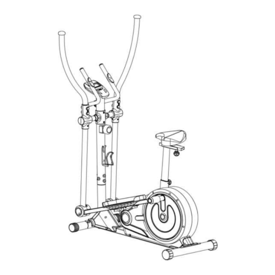
Silver Medal Two In One Cross Trainer
Assembly & User's Instruction-
335/9071
Please Keep for future reference
335/9071
Important –
Please read these instructions fully before assembly or using
These Instructions contain important information which will help you get best from your
equipment and ensure safe and correct assembly, use and maintenance.
If you need help or have damaged or missing parts, call the Customer Helpline: 0845 6000 464
Issue 1 -12/11/12
Advertisement
Table of Contents

Related Manuals for Rogerblack Cross Trainer


Summary of Contents for Rogerblack Cross Trainer
- Page 1 Silver Medal Two In One Cross Trainer Assembly & User’s Instruction- 335/9071 Please Keep for future reference 335/9071 Important – Please read these instructions fully before assembly or using These Instructions contain important information which will help you get best from your equipment and ensure safe and correct assembly, use and maintenance.
-
Page 2: Table Of Contents
Contents Safety Information Components - Parts Components – Fixings Assembly Instructions 5-12 Computer Operation 13-14 Exercise Information . Before Starting Exercise . Muscle Chart . Warning up & Cooling Down 17-18 Care and Maintenance Exploded Parts Diagram Exploded Parts List 21-22 Guarantee... -
Page 3: Safety Information
To reduce the risk of serious injury, read the entire manual before you assemble or operate the Roger Black Silver Two In One Cross Trainer, In particular, note the following safety precautions: aerobic shoes are also required when using the Assembly equipment. -
Page 4: Components - Parts
If you have damaged or missing parts, please Components - Parts call the Customer Helpline: 0845 6000 464. Please check you have all parts listing below Note: Some of the smaller components may be pre-fitted to larger components. Please check carefully before contacting Argos regarding any missing components. -
Page 5: Components - Fixings
Components – Fixings Please check you have all the fixings listed below : Note Some of the fixings are pre-fitted to the larger components. Please check carefully before contacting Argos regarding any missing fixings. -
Page 6: Assembly Instructions
Assembly Instructions Step 1 a. Attach Front Stabilizer (51) to front curve plate of Main Frame (1) using 2 x 20mm Bolts (54), 2 x 34mm Arc Washers (52) and 2x10mm Spring Washers (23). b. Attach Rear Stabilizer (51) to rear curve plate of Main Frame (1) using 2 x 20mm Bolts (54), 2 x 34mm Arc Washers (52) and 2x10mm Spring Washers (23). - Page 7 Assembly Instructions Step 2 a. Attach Foot Pedal (42) to the left Foot Bar (2) using 2 x Knob (44) which are pre-fitted onto (42). b. Attach Foot Bar Assembly (2) to left crank on the Main Frame (1) using,1 x 19mm Corrugated Washer (48), 1 x 2mm Nylon Washer (46),1x 2mm Big Washer (45) and 1x 15mm Hex Bolt (31).
- Page 8 Assembly Instructions Step 3 a. Connect Sensor WireⅠ(83) from the Main Frame(1)to the Sensor Wire Ⅱ(89) which is pre- assembled inside of the Front Post (5). b. Turn the Tension control knob (17) on its highest setting,connect the cable end (17) to the spring hook of the Tension Cable (80),and fit the Tension control knob (17) on Front Post (5) with 50mm...
- Page 9 Assembly Instructions Step 3 -continued d. Attach bottom of the Left Handrail Arm (3L) to the bracket on the front of the Left Foot Pedal Assembly (2) using 1x Axle Bolt (37) and Aircraft Nut (27). e. Repeat step “d” to install Right Handle Rail Arm (3R) to the Right Foot Pedal Assembly(2).
- Page 10 Assembly Instructions Step 4 a. Attach Linkage Cover (40/41) to the pivot of the Left Handrail Arm (3L) and Left Foot Pedal Assembly (2) using 2 x 15mm Philips Screws (13) and 2 x 12mm Philips Screw (39). b. Reap Step a to install Right side. c.
- Page 11 Assembly Instructions Step 5 a. Remove the battery cover from the back of the Computer (7) and insert two AA batteries. b. Connect Sensor WireⅠ(89) to the sensor wire from Computer (7). c. Loop two pulse sensor wires (7) through the hole on the top of Front Post ( 5), then out from the two side holes of the Front Post ( 5).
- Page 12 Assembly Instructions Step 6 a. Attach R/ Front Handrail Rail Cover (87) to the c. Repeat Step a & b to install the L/Front Handrail Right Handrail Arm (3R) using 2 x Philips Cover (36) and L/ Rear Handrail Cover (25) to the Screws (13).
-
Page 13: Assembly Instructions
Assembly Instructions Step 7 a. Attach Saddle (103) onto the Saddle Adjustable frontward or backward to get desired position Bracket (104) using 3 x Aircraft Nuts (27) and tighten using 1 x Knob (109). and 3 x Washers (102). c. Inset the Saddle Post Assembly (101) into Note: Hardware (27) and (102) were pre-assembled the upper opening of the Main Frame, get your to the bottom of the saddle (103) in the factory. -
Page 14: Computer Operation
Computer Operation Functions and operations MODE: This key lets you select and lock on to a particular function which you want. Press to Choose SCAN or LOCK, if you do not want the scan mode, press the Mode key when the pointer is on the function you want which begins flashing. -
Page 15: Computer Operation
Computer Operation Specification Specification Auto Scan Every 4 Seconds 0.0 – 99.9Km/h Speed 0.0 – 999.9Mile or Km (According to inside setting ) Distance 0:00 – 99:59 (Minute: Second ) Time Function 0.0 – 999.9 Kcal Calories 0.0 – 999.9 Km or Mile (According to inside setting ) Odometer Circles/Min 40 –... -
Page 16: Exercise Information
Exercising Information Before starting to exercise How you begin your exercise programme depends on your physical condition. If you have been inactive for several years or are severely overweight, you must start slowly and increase a few minutes per workout. Initially, you may be able to exercise only for a few minutes in your target zone;... -
Page 17: Muscle Chart
As always, consult your doctor before beginning any exercise program. Targeted Muscle Groups The exercise routine that is performed on the Silver Two In One Cross Trainer will develop the upper and lower body muscle groups. These muscle groups are highlighted on the muscle chart below. -
Page 18: Warning Up & Cooling Down
Exercising Information Warming up and Cooling down exercises Each workout should include the following three parts: 1. A warm-up, consisting of 5 to 10 minutes of stretching and light exercise. A proper warm-up increases your body temperature, heart rate, and circulation in preparation for exercise. 2. - Page 19 Exercising Information Calf/achilles stretch With one leg in front of the other, reach forward and place your hands against a wall. Keep your back leg straight and your back foot flat on the floor. Bend your front leg, lean forward and move your hips toward the wall.
-
Page 20: Care And Maintenance
Care and Maintenance the equipment again until it is use of your exercise product Examine the equipment in perfect working order. or if you think that you may periodically in order to detect have parts missing, contact any damage or wear which the manufacturer, their The equipment can be may have been produced. -
Page 21: Exploded Parts Diagram
Exploded Parts Diagram... -
Page 22: Exploded Parts List
Exploded Parts List Part Description Qty. Part Description Qty. Main Frame Ø38×2mm Nylon Washer Foot Bar M8 x 25mm Hex Bolt Left Handrail Arm Ø8mm Washer Right Handrail Arm M8x45mm Carriage Bolt Left Handrail Ø25mm Corrugated Washer Right Handrail Ø38×Ø25mm Nylon Bushing Front Post L/Front Handle Rail Cover Handle Bar... - Page 23 Exploded Parts List Part Description Qty. Part Description Qty. M10 Aircraft Nut R/ Rear Handrail Cover Sensor Wire Ⅱ M8x70mm Tension Adjustable Bolt M6x12mm Dome Head Philips Screw Axle Spring Lock Ring Axle Wire Holder 6202-2RS Bearing Belt Tension Lock M6 Aircraft Nut M6n45mm Tension Adjustable Bolt 6004-2RS Bearing...
-
Page 24: Guarantee
Guarantee Product Guarantee This product is guaranteed against manufacturing defects from a period of Year This product is guaranteed for twelve months from the date of original purchase. Any defect that arises due to faulty materials or workmanship will either be replaced, refunded or repaired free of charge where possible during this period by the dealer from whom you purchased the unit.
Need help?
Do you have a question about the Cross Trainer and is the answer not in the manual?
Questions and answers