
Related Manuals for Robertshaw Smart Sense SMART 1000


Summary of Contents for Robertshaw Smart Sense SMART 1000
- Page 1 Uni-Line® SMART 1000 Touchscreen Thermostat Installation Manual www.robertshaw.com ©2015 Robertshaw 12/15 – 352-00242-001...
-
Page 3: Important Safety Information
IMPORTANT SAFETY INFORMATION WARNING: ELECTRICAL SHOCK HAZARD – Turn off power at the main power source by unscrewing fuse or switching circuit breaker to the OFF position before installing, removing, or cleaning this thermostat. WARNING: FIRE AND ELECTRIC SHOCK HAZARD – This device should be installed by a qualified service technician wit ue regard for safety as improper installation could result in a fire and... -
Page 5: Table Of Contents
TABLE OF CONTENTS Introduction ............................4 Getting Started ............................5 Installing the Thermostat ........................6, 8 Disassembly ..........................6 Thermostat Location ......................6 Mounting the Subbase ......................6, 7 Terminal Designations ......................8 Setting the System Switches ........................9 System Switch Functions ........................10 Installing the Batteries ..........................11 Typical System Wiring Diagrams .....................12, 20 Heat only (Gas) ........................12 Heat only (Electric)........................13 Cool only (Single or Multi-stage) ...................14... - Page 6 TABLE OF CONTENTS TABLE OF CONTENTS 2 Heat / 1 Cool (Fossil Fuel) ....................19 3 Heat / 2 Cool (Fossil Fuel) ....................20 Installer Setup Menu ........................21,38 Entering the Setup Menu ......................21 Selecting Programmable or Non-programmable Operation ..........22 Selecting Number of Program Events ...................23 Selecting Mode ........................24 Selecting Programmable Fan ....................25 Assigning Auxiliary Contacts ....................26...
- Page 7 TABLE OF CONTENTS Remote Sensor Installation ......................41, 43 Remote Sensor Types ......................41 SMART-R-02 Indoor Sensor Installation .................41, 42 SMART-R-03 Outdoor Sensor Installation ................42 Temperature/Resistance Chart ....................43 Display Functions ..........................44 Testing ............................45, 49 Fan Operation ........................45 Conventional Heating ......................45 Conventional Cooling .....................45, 46 Conventional Heat Pump .....................46 Fossil Fuel ..........................47 Low Balance Point ......................47, 48...
-
Page 8: Introduction
INTRODUCTION The SMART 1000 is a feature-rich touchscreen thermostat that can be battery powered or hardwired to the HVAC equipment. Using a common sense approach to the installation will ensure this product is installed properly and to the customer’s satisfaction. Please take time to read and understand this manual so that installation and testing is performed in an efficient manner. -
Page 9: Getting Started
GETTING STARTED As with any HVAC project, careful installation is the key to a successful outcome. Time taken during the installation process will be rewarded with fewer call-backs. The steps required to install the SMART 1000 thermostat are as follows. 1. -
Page 10: Installing The Thermostat
INSTALLING THE THERMOSTAT DISASSEMBLY There are two release slots located on the bottom of the thermostat. Gently push the flat blade of a small screwdriver into one slot at a time and pry upward until the catch disengages. Carefully swing the thermostat upward and away from the subbase. - Page 11 INSTALLING THE THERMOSTAT Pull the control wires through the large opening in the thermostat subbase. Next, level and mount the subbase on the wall using the supplied anchors and screws. (Figure 2) Do not over tighten the mounting screws as the subbase may warp causing the improper seating of the thermostat connecting pins to the terminal blocks.
-
Page 12: Terminal Designations
INSTALLING THE THERMOSTAT TERMINAL DESIGNATIONS TERMINAL DESIGNATION Outdoor Sensor Sensor Common Indoor Sensor Auxiliary Contacts W2/OB Second Stage Heat or Reversing Valve First Stage Cool or First Stage Compressor Second Stage Cool or Second Stage Compressor First Stage Heat/Auxiliary/Emergency Heat 24V AC Hot 24V AC Common... -
Page 13: Setting The System Switches
SETTING THE SYSTEM SWITCHES The SMART 1000 contains a set of four system switches located on the thermostat printed circuit board. (Figure 3) The switches are used to match the thermostat operation and relay outputs with the HVAC system requirements. Refer to the system switch functions on the next page to properly configure the thermostat. -
Page 14: System Switch Functions
SYSTEM SWITCH FUNCTIONS Switch 1 - Equipment Type OFF Heat / Cool (Default). ON For heat pump equipment. Switch 2 - Fan or When Switch 1 is OFF (Heat Cool Mode) Reversing Valve OFF Gas Heat - Heater controls fan (Default). ON Electric Heat -Thermostat calls fan with heat. -
Page 15: Installing The Batteries
INSTALLING THE BATTERIES The SMART 1000 comes with two AA batteries. Even if the thermostat is hardwired, battery backup is recommended to maintain the real-time clock in the event of a power failure. All other memory is non-volatile in the event of battery or primary power loss. -
Page 16: Typical System Wiring Diagrams
TYPICAL SYSTEM WIRING DIAGRAMS HEAT ONLY (GAS) OPTIONAL REMOTE SENSOR TERMINALS THERMOSTAT EQUIPMENT HEAT 1 OUTDOOR INDOOR SENSOR SENSOR RELAY RELAY LINE 24 V (Fan is Optional) Switch Settings Switch 1 = OFF Heat/Cool Switch 2 = OFF Equipment controls fan on call for heat Switch 3 = OFF Single Stage Switch 4 = OFF... -
Page 17: Heat Only (Electric)
TYPICAL SYSTEM WIRING DIAGRAMS HEAT ONLY (ELECTRIC) OPTIONAL REMOTE SENSOR TERMINALS THERMOSTAT EQUIPMENT HEAT 1 OUTDOOR INDOOR SENSOR SENSOR RELAY RELAY LINE 24 V Switch Settings Switch 1 = OFF Heat/Cool Switch 2 = ON Thermostat controls fan on call for heat Switch 3 = OFF Single Stage Switch 4 = OFF... -
Page 18: Cool Only (Single Or Multi-Stage)
TYPICAL SYSTEM WIRING DIAGRAMS COOL ONLY (SINGLE OR MULTI-STAGE) OPTIONAL REMOTE SENSOR TERMINALS THERMOSTAT EQUIPMENT COOL 2 OUTDOOR INDOOR RELAY SENSOR SENSOR COOL 1 RELAY RELAY LINE 24 V Switch Settings Switch 1 = OFF Heat/Cool Switch 2 = OFF Fan energized on call for cooling Switch 3 = OFF/ON OFF = Single Stage ON = Multi-stage... -
Page 19: Heat/1 Cool (Gas)
TYPICAL SYSTEM WIRING DIAGRAMS 1 HEAT/1 COOL (GAS) OPTIONAL REMOTE SENSOR TERMINALS THERMOSTAT EQUIPMENT HEAT 1 OUTDOOR INDOOR SENSOR SENSOR RELAY COOL 1 RELAY RELAY LINE 24 V Switch Settings Switch 1 = OFF Heat/Cool Switch 2 = OFF Fan energized on call for cooling Switch 3 = OFF Single Stage Switch 4 = OFF... -
Page 20: Heat/2 Cool (Gas)
TYPICAL SYSTEM WIRING DIAGRAMS 2 HEAT/2 COOL (GAS) OPTIONAL REMOTE SENSOR TERMINALS THERMOSTAT EQUIPMENT HEAT 2 COOL 2 HEAT 1 OUTDOOR INDOOR RELAY RELAY RELAY SENSOR SENSOR COOL 1 RELAY RELAY LINE 24 V Switch Settings Switch 1 = OFF Heat/Cool Switch 2 = OFF Fan energized on call for cooling... -
Page 21: Heat/1 Cool (Heat Pump)
TYPICAL SYSTEM WIRING DIAGRAMS 2 HEAT/1 COOL (HEAT PUMP) OPTIONAL REMOTE SENSOR TERMINALS THERMOSTAT EQUIPMENT OUTDOOR INDOOR VALVE RELAY SENSOR SENSOR COMP 1 RELAY RELAY LINE 24 V Switch Settings Switch 1 = ON Heat Pump Switch 2 = OFF/ON OFF = ‘O’... -
Page 22: Heat/2 Cool (Heat Pump)
TYPICAL SYSTEM WIRING DIAGRAMS 3 HEAT/2 COOL (HEAT PUMP) OPTIONAL REMOTE SENSOR TERMINALS THERMOSTAT EQUIPMENT COMP 2 OUTDOOR INDOOR VALVE RELAY RELAY SENSOR SENSOR COMP 1 RELAY RELAY LINE 24 V Switch Settings Switch 1 = ON Heat Pump Switch 2 = OFF/ON OFF = ‘O’... -
Page 23: Heat/1 Cool (Fossil Fuel)
TYPICAL SYSTEM WIRING DIAGRAMS 2 HEAT/1 COOL (FOSSIL FUEL) OPTIONAL REMOTE SENSOR TERMINALS THERMOSTAT EQUIPMENT OUTDOOR INDOOR VALVE RELAY SENSOR SENSOR COMP 1 RELAY RELAY LINE 24 V Switch Settings Switch 1 = ON Heat Pump Switch 2 = OFF/ON OFF = ‘O’... -
Page 24: Heat / 2 Cool (Fossil Fuel)
TYPICAL SYSTEM WIRING DIAGRAMS 3 HEAT / 2 COOL (FOSSIL FUEL) OPTIONAL REMOTE SENSOR TERMINALS THERMOSTAT EQUIPMENT COMP 2 OUTDOOR INDOOR VALVE RELAY RELAY SENSOR SENSOR COMP 1 RELAY RELAY LINE 24 V Switch Settings Switch 1 = ON Heat Pump Switch 2 = OFF/ON OFF = ‘O’... -
Page 25: Installer Setup Menu
INSTALLER SET-UP MENU ENTERING THE SET-UP MENU Tap the display to bring on the back light then touch and hold both the Clock and Mode section for 5 seconds to enter the Installer Menu. 01/01/2012 • To advance through the menu, touch the Mode (Next) section. •... -
Page 26: Selecting Programmable Or Non-Programmable Operation
INSTALLER SET-UP MENU SELECTING THE PROGRAMMABLE OR NON-PROGRAMMABLE OPERATION The first menu 01 selects programmable or non-programmable operation. Press the UP or DOWN arrows to change the selection. Back Next Program Morning Day Evening Night 7 = 7-Day Programmable (Factory Default) 0 = Manual Mode (Non-programmable) -
Page 27: Selecting Number Of Program Events
INSTALLER SET-UP MENU SELECTING NUMBER OF PROGRAM EVENTS (ONLY DISPLAYED WHEN 01 = 7) If menu 01 is set to 7, the thermostat can be configured for 4 or 2 schedules per day. Back Next 4 = 4 schedules per day (Factory Default) 2 = 2 schedules per day... -
Page 28: Selecting Mode
INSTALLER SET-UP MENU SELECTING MODE Menu 03 selects the mode of operation. The factory default is 1 for Manual changeover. Back Next Program 0 = Auto-changeover (Heat/Cool/Auto/Off for Heat/Cool) (Heat/Cool/Auto/E.Heat/Off for Heat Pump 1 = Manual Changeover (Heat/Cool/Off) or (Heat/Cool/E.Heat/Off) (Factory Default) 2 = Heating Only (Heat/Off) or (Heat/E.Heat/Off) 3 = Cooling Only (Cool/Off) -
Page 29: Selecting Programmable Fan
INSTALLER SET-UP MENU SELECTING PROGRAMMABLE FAN Menu 04 selects the Programmable Fan option which allows selecting continuous or auto fan operation for each program event when programmable mode is selected. The factory default is 0. Back Next Program 0 = No Programmable Fan (Factory Default) 1 = Programmable Fan Refer to the Owners Manual for selecting continuous or auto fan for each scheduled event when the Programmable Fan option is ON. -
Page 30: Assigning Auxiliary Contacts
INSTALLER SET-UP MENU ASSIGNING AUXILIARY CONTACTS Menu 05 assigns the auxiliary dry relay contacts (AUX) as Normally Open or Normally closed when the Programmable Fan Option 04 is ON. Whenever Programmable Fan is in the Always On mode (constant ventilation) for a selected program period, the relay contact will go open or closed based on the auxiliary relay option selection. -
Page 31: Selecting Touchscreen Lock Options
INSTALLER SET-UP MENU SELECTING TOUCHSCREEN LOCK OPTIONS Menu 06 allows you to prevent changes to all or part of the touchscreen functions. The factory default is 0. Touch the UP or DOWN arrows to change the selection. Next Back 0 = All functions unlocked (Factory Default) 1 = All functions locked except setpoint adjustment 2 = All functions locked... -
Page 32: Selecting The Cooling Setpoint Limit
INSTALLER SET-UP MENU SELECTING THE COOLING SETPOINT LIMIT Menu 07 selects the minimum cooling setpoint. The factory default is 50°F (10°C) Touch the UP or DOWN arrows to adjust the limit from 43° - 122°F (6° - 50°C). Next Back... -
Page 33: Selecting The Heating Setpoint Limit
INSTALLER SET-UP MENU SELECTING THE HEATING SETPOINT LIMIT Menu 08 selects the maximum heating setpoint limit. The factory default is 90°F (32°C). Touch the UP or DOWN arrows to adjust the limit from 41° - 120°F (5° - 49°C). Heat Next Back... -
Page 34: Selecting Backlight Option
INSTALLER SET-UP MENU SELECTING BACKLIGHT OPTION Menu 09 allows you to select the backlight option. The factory default is ON. Touch the UP or DOWN arrows to change the display option. Next Back 0 = Backlight on for 10 seconds when screen is touched 1 = Backlight on high for 10 seconds when screen is touched and then low continuously. -
Page 35: Selecting Adaptive Recovery Option
INSTALLER SET-UP MENU SELECTING ADAPTIVE RECOVERY OPTION Menu 10 allows you to select the Adaptive Recovery option. Only displayed when menu option 01 is set to 7 . Adaptive Recovery compares the space temperature deviation from setpoint and rate of recovery history to bring the equipment on and reach the setpoint at the scheduled start time. -
Page 36: Selecting First Stage Heating And Cooling Differential Option
INSTALLER SET-UP MENU SELECTING FIRST STAGE HEATING AND COOLING DIFFERENTIAL OPTION Menu 11 is used to adjust the heating and cooling differential. The factory default is 1=1°F (0.5°C). This represents the temperature above the cooling setpoint or below the heating setpoint when the equipment is energized. Touch the UP or DOWN arrows to change the differential. -
Page 37: Selecting Second Stage Heating And Cooling Differential Option
INSTALLER SET-UP MENU SELECTING SECOND STAGE HEATING AND COOLING DIFFERENTIAL OPTION Menu 12 is used to adjust the second stage heating and cooling differential. The factory default is 1=1°F ( 0.5°C). This represents the temperature above the first stage cooling differential or below the first stage heating differential when second stage is energized. -
Page 38: Selecting Third Stage Heating Differential Option
INSTALLER SET-UP MENU SELECTING THIRD STAGE HEATING DIFFERENTIAL OPTION Menu 13 is used to adjust the third stage heating differential. Only displayed when SW 3 is ON. The factory default is 1 =1°F ( 0.5°C). This represents the temperature below the second stage heating differential when third stage heat is energized. -
Page 39: Selecting Demand Staging Or Locked Staging Option
INSTALLER SET-UP MENU SELECTING DEMAND STAGING OR LOCKED STAGING OPTION Menu 14 is used to select how the thermostat will stage the equipment. The factory default is 0 which = Demand Staging. Demand Staging allows the thermostat to upstage or downstage the equipment based on the stage differential settings. -
Page 40: Sensor Calibration
INSTALLER SET-UP MENU SENSOR CALIBRATION Menu 15 allows you to re-calibrate the internal or a single indoor remote sensor. When a remote sensor is wired to the SC and S1 terminals, the internal sensor is automatically disabled. The factory default is 0 . Touch the UP or DOWN arrows to adjust the calibration from -5°... -
Page 41: Selecting Low Balance Point Option
INSTALLER SET-UP MENU SELECTING LOW BALANCE POINT OPTION Menu 16 allows you to select a low balance point setting when the thermostat is configured for Heat Pump or Fossil Fuel and an outdoor sensor is used. When the outdoor temperature falls below the balance point setting, the compressor is locked out and only auxiliary electric heat or fossil fuel furnace is used for heating. -
Page 42: Selecting High Balance Point Option
INSTALLER SET-UP MENU SELECTING HIGH BALANCE POINT OPTION Menu 17 allows you to select a high balance point setting when the thermostat is configured for Heat Pump or Fossil Fuel. When the outdoor temperature rises above the balance point setting, the auxiliary electric heat or fossil fuel furnace is locked out and only the heat pump is used for heating. -
Page 43: Selecting Temperature Display Format
INSTALLER SET-UP MENU SELECTING TEMPERATURE DISPLAY FORMAT Menu 18 allows you to select either degree F (Fahrenheit) or degree C (Celsius) display. Next Back F = Fahrenheit (Factory Default) C = Celsius... -
Page 44: Enabling E.heat Mode
INSTALLER SET-UP MENU SELECTING EMERGENCY HEATING FUNCTION Menu 19 enables or disables the emergency heating function. If enabled the W1 relay can be manually selected for heating, locking out the heat pump. Next Back 0 = E.HEAT function disabled 1 = E.HEAT function enabled... -
Page 45: Remote Sensor Installation
REMOTE SENSOR INSTALLATION REMOTE SENSOR TYPES The SMART 1000 can accommodate both an indoor and outdoor remote sensor. For indoor applications, the SMART-R-02 remote sensor can be wired to the thermostat SC and S1 terminals. Each sensor contains two thermistors wired in series with a switch to select one or both sensors. -
Page 46: Smart-R-03 Outdoor Sensor Installation
REMOTE SENSOR INSTALLATION Use a separate 18-2 shielded cable for sensor wiring. Prior to wiring the sensor to the thermostat, use an ohm-meter or multi-meter to measure the resistance of the sensor. Measure at the end of the wires that will connect to the thermostat. Confirm the resistance value (within 5%) to the temperature where the sensor is mounted. -
Page 47: Temperature/Resistance Chart
REMOTE SENSOR INSTALLATION TEMPERATURE/RESISTANCE CHART Temperature Resistance Temperature Resistance F° (°C) (KΩ) F° (°C) (KΩ) 34°F (1°C) 34.6 70°F (21°C) 11.9 40°F (4.4°C) 26.1 81°F (27°C) 50°F (10°C) 19.9 90°F (32°C) 61°F (16°C) 15.3 100°F (38°C) NTC type 2 sensor - 10KΩ @ 77°F (25°C) -
Page 48: Display Functions
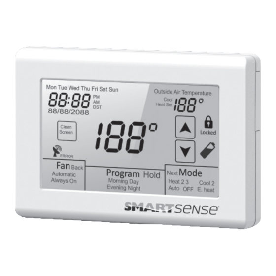
DISPLAY FUNCTIONS DISPLAYED WITH OUTSIDE DAYLIGHT SAVINGS TIME DAYS OF THE WEEK AIR TEMPERATURE DISPLAYED WHEN DST IS ACTIVE (OPTIONAL OUTDOOR SENSOR REQUIRED) TIME OF DAY 12 HOUR ONLY Mon Tue Wed Thu Fri Sat Sun Outside Air Temperature WITH AM/PM SET TEMPERATURE INDICATION Cool... -
Page 49: Testing
TESTING FAN OPERATION Touch MODE until the word OFF is displayed. Touch FAN until the words Always On appear. After a brief moment, the internal fan relay ‘G’ will energize and the system fan should operate. Touch FAN again until the word Automatic appears. After a brief moment, the internal fan relay will de-energize and the system fan will shut off. -
Page 50: Conventional Heat Pump
TESTING Note: On a call for cooling, the thermostat activates a 3 minute time delay before the cooling relay ‘Y1’ is energized. After the time delay, the internal fan ‘G’ and cooling relay ‘Y1’ will energize. The word Cool will flash. If the thermostat has been configured for two stage cooling, lower the setpoint below the second stage differential and Cool 2 will flash indicating the ‘Y2’... -
Page 51: Fossil Fuel
TESTING FOSSIL FUEL When the SMART 1000 is configured for fossil fuel operation, testing is the same as a heating and cooling system with the exception that a 3 minute time delay is activated before the ‘Y1’ compressor relay will energize on a call for heating or cooling. -
Page 52: High Balance Point
TESTING To test the low balance point setting, set Option 16 above the displayed outdoor temperature and force a call for heating. Only the auxiliary heat relay ‘W1’ should energize. After testing, reset the low balance point setting to a normal operating range. -
Page 53: Programmable Fan
TESTING the designated time. This calculation involves a complex control algorithm that compares the space temperature deviation from setpoint and rate of recovery history. PROGRAMMABLE FAN Programmable Fan (Installer Option 04 = 0) is used to program the fan operation along with the thermostat schedule. -
Page 54: Basic Troubleshooting
BASIC TROUBLESHOOTING SYMPTOM POSSIBLE FAULT AND REMEDY No LCD display If the thermostat is battery powered only, remove the battery compartment and check to see that the positive (+) and negative (-) ends of each battery are oriented properly. Also make sure that the thermostat is securely attached to the subbase with no exposed gaps. - Page 55 BASIC TROUBLESHOOTING SYMPTOM POSSIBLE FAULT AND REMEDY Heat or Cool is flashing This is not a fault but indicates that the thermostat heating or cooling relay is energized. Depending upon the equipment configuration, Heat 2 or Cool 2 will also be displayed if a second stage is energized. Heat 3 is also displayed for heat pumps having three heating stages.
-
Page 56: Specifications
SPECIFICATIONS Input Voltage (Hardwired) 20-30V AC 50/60 Hz Relay Rating 24V AC @ 1 Amp maximum per relay Battery Power (2) AA 1.5 V Operating Temperature 0°F to 149°F (0°C to 65°C) Operating Relative Humidity 0-95% RH (non-condensing) Storage Temperature 0°F to 149°F (0°C to 65°C) Overall Size 140W x 95 H x 35mm D... - Page 57 (5) years from the date of purchase (the “Warranty Period”). If any Product fails within the applicable Warranty Period, Robertshaw shall, at its option, repair or replace the Product or credit the purchase price, provided the Product is returned to Robertshaw’s facility or designated agent with transportation charges prepaid, and the Product, upon examination by Robertshaw, is found not to conform to the Warranty.
- Page 58 4. Within North America (USA and Canada), all cartons must be clearly identified as WARRANTY PRODUCT and returned to: USA Distributors: Warranty Department Robertshaw 1921 Anei Circle, Brownsville, TX 78521 USA Canada Distributors: Warranty Department Robertshaw 4060 Ridgeway Drive, Unit 14 Mississauga, ON L5L5X9 CANADA...
- Page 60 Uni-Line® Robertshaw®, Uni-Line® and SmartSense ® trademarks of Robertshaw, its subsidiaries and/or affiliated companies. All other br ands mentioned may be the trademarks of their respective owners. Customer Service Telephone 1.800.304.6563 Customer Service Facsimile 1.800.426.0804 HVACCustomerService@robertshaw.com www.uni-line.com For Technical Service www.robertshaw.com...
Need help?
Do you have a question about the Smart Sense SMART 1000 and is the answer not in the manual?
Questions and answers