Advertisement
Optional Accessory: Wall Cover-Up Plate F61-2663, 6 3/4" W x 4 1/2" H
INDEX
Thermostat Installation
2-4
Wiring
2
3-4
Installer Menu
Using the Thermostat
5-7
Thermostat Overview
5
User Menu
6
Thermostat Operation
6
7
Thermostat Schedule
Troubleshooting
7-8
Homeowner Help Line
8
SPECIFICATIONS
Electrical Rating:
Battery Power ..................................... mV to 30 VAC, NEC Class II, 50/60 Hz
Input-Hardwire .................................... 20 to 30 VAC, NEC Class II, 50/60 Hz
Terminal Load .......................................... 1.0 A per terminal, 1.5A maximum all terminals combined
Setpoint Range ........................................ 45° to 99° F (7° to 37° C)
Rated Differentials:
Fast
Heat (@ 6°F/ Hr) .................................. 0.5°F
Cool (@ 6°F/ Hr) .................................. 0.9°F
Operating Ambient .................................. 32°F to +105°F (0° to +41°C)
Display Temperature Range ....................... 32°F to +99°F (0 to 37°C)
Operating Humidity ................................. 90% non-condensing max
Shipping Temperature Range ................... -20°F to + 150°F (-29° to +65°C)
Thermostat Dimensions ........................... 3-3/4" H x 6" W x 1-1/8" D
emersonthermostats.com
white-rodgers.com
1F83C-11NP (Non-Programmable)
Installation and Operating Instructions
80 Series Single Stage Thermostat
Battery Powered or Hardwired with Common
Maximum
Thermostat Applications
Stages
Heat/Cool
Conventional Gas, Oil, Electric (mV and
24V), Heat Only, Cool Only or Heat/
Cool Systems
Heat Pump (air source or geothermal)
with no Aux. Heat
MERCURY NOTICE: This product does not contain
mercury. However, this product may replace a product
that contains mercury. Mercury and products containing
mercury must not be discarded in household trash.
Refer to www.thermostat-recycle.org for information
on disposing of products containing mercury.
Med
Slow
0.75°F
1.9°F
1.2°F
1.7°F
PART NO. 37-7479A-EN
WIRING
Refer to equipment manufacturer's instructions for specific system wiring information. After
wiring, see INSTALLER MENU for proper thermostat configuration. Wiring table shown are
for typical systems and describe the thermostat terminal functions.
Terminal Designations
*When both RC and RH wires are present, cut RC/RH jumper (see next page).
**For heat pump systems, add a jumper wire to connect terminals Y and W
1/1
1/1
Precautions
• Do not exceed the specification ratings.
• All wiring must conform to local and national electrical codes and ordinances.
• This control is a precision instrument, and should be handled carefully. Rough handing or
distorting components could cause the control to malfunction.
!
Do not use on circuits exceeding specified voltage.
Higher voltage will damage control and could
cause shock or fire hazard.
Do not short out terminals on gas valve or primary
control to test. Short or incorrect wiring will burn
out thermostat and could cause personal injury
and/or property damage.
1504
THERMOSTAT INSTALLATION
RC*
Power for Cooling
RH*
Power for Heating
Changeover Terminal-Energized in Heat (B) or Cool (O)
O/B
for Heat Pump or Damper Systems
Y**
Cooling Relay
G
Fan Relay
W**
Heating Relay
C
Common wire for 24V (optional with batteries)
WARNING
To prevent electrical shock and/or equipment
damage, disconnect electrical power to system,
at main fuse or circuit breaker box,until
Terminal Function
Leveling Thermostat
Leveling is for appearance only and
will not affect thermostat operation.
CAUTION
!
installation is complete.
2
Advertisement

Related Manuals for Emerson 1F83C-11NP


Summary of Contents for Emerson 1F83C-11NP
-
Page 1: Specifications
1F83C-11NP (Non-Programmable) THERMOSTAT INSTALLATION Installation and Operating Instructions 80 Series Single Stage Thermostat WIRING Battery Powered or Hardwired with Common Refer to equipment manufacturer’s instructions for specific system wiring information. After wiring, see INSTALLER MENU for proper thermostat configuration. Wiring table shown are for typical systems and describe the thermostat terminal functions. -
Page 2: Test Equipment
INSTALLER MENU (C0ntinued) Installer’s Menu # Default Setting Description Settings (flashing icons) (Hold Menu 8 Seconds) Battery Location °F – Fahrenheit Fahrenheit or Celsius °F Premium AA alkaline batteries °C – Celsius are required when C-wire is Temperature Display not available. When C-wire is Adjustment (adjust the displayed -5 to +5 available, the batteries provide... -
Page 3: Thermostat Overview
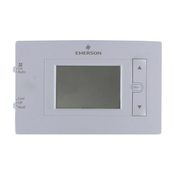
USER MENU USING THE THERMOSTAT To customize thermostat settings, press the Menu button from the home screen. Use the Next button to advance through menu items. Press to change the setting. THERMOSTAT OVERVIEW Before you begin using your thermostat, you should be familiar with its features, display and the location/operation of the thermostat buttons and switches. -
Page 4: Troubleshooting
Display can be adjusted +/-5°. See User Menu item & Thermometer adjustment Disagree (Troubleshooting continued on next page) HOMEOWNER HELP LINE: 1-800-284-2925 White-Rodgers is a business of Emerson Electric Co. The Emerson logo is a trademark and service mark www.white-rodgers.com of Emerson Electric Co. www.emersonclimate.com...
Need help?
Do you have a question about the 1F83C-11NP and is the answer not in the manual?
Questions and answers
I have an oil boiler - baseboard fin-coil units - heat only - there is no air conditioning with my system. I would like to install this thermostat. However, there are only 2 wires coming from the boiler both are black. Can I use this unit. If so how do I connect it?
Yes, the Emerson 1F83C-11NP thermostat can be installed with a two-wire system from an oil boiler. Since it supports Heat Only systems, it should be compatible. To connect it, use the following wiring method:
1. Identify the two thermostat wires from the oil boiler.
2. Connect one wire to the R terminal (power).
3. Connect the other wire to the W terminal (heat call).
4. Ensure the system is properly powered and configured in the installer menu.
If needed, consult the installation guide for specific settings.
This answer is automatically generated
The **** on the furnace cycles on and off constantly, even if the thermostat does not ask the furnace to run
The Emerson 1F83C-11NP thermostat might cause the furnace to cycle on and off constantly if the heat cycle rate is set too high. In the installer menu, the heat cycle rate can be adjusted to FAST, MEDIUM, or SLOW. A higher setting (FAST) causes the furnace to turn on and off more frequently. Adjusting this setting to MEDIUM or SLOW can reduce the cycling frequency. To access this menu, hold the "Menu" button for 8 seconds and adjust the heat cycle rate (Installer Menu #30).
This answer is automatically generated
can I replace battery on this thermostat?
can i replace battery
Yes, the Emerson thermostat model 1F83C-11NP has batteries that can be removed and reinstalled, as mentioned in the reset instructions.
This answer is automatically generated
Which terminal would I connect the AUX E wire to?