Table of Contents
Advertisement
Advertisement
Table of Contents

Related Manuals for TREND SRT


Summary of Contents for TREND SRT
- Page 1 MANU-SRT v3.0_ MANU/SRT v3.0 13/10/2014 14:20 Page 34...
-
Page 2: Table Of Contents
MANU-SRT v3.0_ MANU/SRT v3.0 13/10/2014 14:20 Page 1 TECHNICAL DATA Dear Customer Thank you for purchasing this Trend product, we Voltage: UK & Eire 240V hope you enjoy many years of creative and Europe 230V productive use. On/off switch No-volt release... -
Page 3: Safety
MANU-SRT v3.0_ MANU/SRT v3.0 13/10/2014 14:20 Page 2 ■ Use the attachment with the power ■ Connect dust extraction equipment. SAFETY tools and accessories specified in If devices are provided for the this manual only. Do not force the connection of dust extraction and... - Page 4 MANU-SRT v3.0_ MANU/SRT v3.0 13/10/2014 14:20 Page 3 Cleaner ® . The use of a dry fixed to or adjacent to the ■ Eye protection. Wear safety lubricant (Trendicote ® PTFE) will attachment and that it is used act as a preventative. Do not use correctly.
-
Page 5: Electrical Safety
MANU-SRT v3.0_ MANU/SRT v3.0 13/10/2014 14:20 Page 4 ELECTRICAL SAFETY Mains Plug Replacement Never connect the live (L) or (UK & Ireland only) neutral (N) wires to the earth pin marked E or Always check the condition of the cable and plug before starting with your work. -
Page 6: Items Enclosed
MANU-SRT v3.0_ MANU/SRT v3.0 13/10/2014 14:20 Page 5 ITEMS ENCLOSED... -
Page 7: Description Of Parts
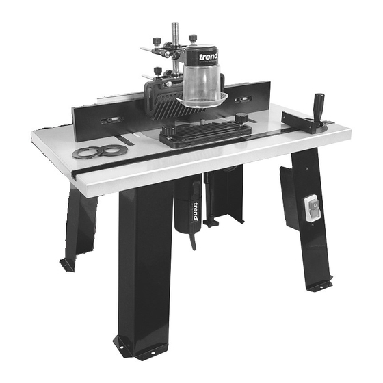
MANU-SRT v3.0_ MANU/SRT v3.0 13/10/2014 14:20 Page 6 DESCRIPTION OF PARTS Table top Legs Insert plate Back fence No-volt release switch Dust spout Side pressure guard Top pressure guard Fence cheek stepper Top guard Mitre fence Lead-on pin Insert ring... -
Page 8: Assembly Fitting Legs
MANU-SRT v3.0_ MANU/SRT v3.0 13/10/2014 14:20 Page 7 ASSEMBLY Fitting Legs Identify Parts x 16 x 16... -
Page 9: Fitting Switch
MANU-SRT v3.0_ MANU/SRT v3.0 13/10/2014 14:20 Page 8 Fitting Switch Requires: No 1 Phillips ® Screwdriver (not supplied). No 1... -
Page 10: Fitting Scaled Label
MANU-SRT v3.0_ MANU/SRT v3.0 13/10/2014 14:20 Page 9 Fitting Scaled Label Apply the labels with the zero lining up with the centre line on the insert plate. -
Page 11: Router Compatibility
MANU-SRT v3.0_ MANU/SRT v3.0 13/10/2014 14:20 Page 10 Router Compatibility See machine screw illustrations on opposite page. Three machine screws (F) are supplied as standard with the SRT table Screw Make Router Model x Qty TREND T3, T5, T5 MK2... -
Page 12: Screw Selection & Re-Drilling
MANU-SRT v3.0_ MANU/SRT v3.0 13/10/2014 14:20 Page 11 Screw Selection Re-drilling Fixing Plate Only ■ Remove the plastic base of the router. Alternatively a photocopy or an outline of the base can be made of the plastic base instead. ■ Align the centre of the fixing plate to the router base and secure them together. -
Page 13: Fitting Dust Spout To Back Fence
MANU-SRT v3.0_ MANU/SRT v3.0 13/10/2014 14:20 Page 12 Fitting Dust Spout to Back Fence Identify Parts -12-... -
Page 14: Fitting Insert Rings & Top Pressure
MANU-SRT v3.0_ MANU/SRT v3.0 13/10/2014 14:20 Page 13 Fitting Insert Rings 20mm 30mm 40mm 54mm -13-... - Page 15 MANU-SRT v3.0_ MANU/SRT v3.0 13/10/2014 14:20 Page 14 Fitting Top Pressure -14-...
-
Page 16: Fitting Back Fence & Top Guard
MANU-SRT v3.0_ MANU/SRT v3.0 13/10/2014 14:20 Page 15 Fitting Back Fence Plastic -15-... - Page 17 MANU-SRT v3.0_ MANU/SRT v3.0 13/10/2014 14:20 Page 16 Fitting Top Guard 10mm max. -16-...
-
Page 18: Fitting Side Pressure & Mitre Fence
MANU-SRT v3.0_ MANU/SRT v3.0 13/10/2014 14:20 Page 17 Fitting Side Pressure 30mm Metal -17-... - Page 19 MANU-SRT v3.0_ MANU/SRT v3.0 13/10/2014 14:20 Page 18 Fitting Mitre Fence -18-...
-
Page 20: Bench Fixing & Dust Extraction
MANU-SRT v3.0_ MANU/SRT v3.0 13/10/2014 14:20 Page 19 Bench Fixing Fix the router table to the workbench or workboard with eight No.8 x 3/4” pan head screws (not supplied). 500mm 600mm -19-... - Page 21 MANU-SRT v3.0_ MANU/SRT v3.0 13/10/2014 14:20 Page 20 Dust Extraction - Fitting Hose T30/22 Hose Ref: T30/22 or CRT/4 CRT/4 not included. Option 1 Option 2 T30/22 CRT/4 58mmø -20-...
-
Page 22: Operation
MANU-SRT v3.0_ MANU/SRT v3.0 13/10/2014 14:20 Page 21 OPERATION No-Volt Release Switch Plug machine into socket in no-volt release switch. Put plug of switch into mains supply. Switch on router Press green button to switch on. To switch off press red button. -
Page 23: Back Fence Adjustment
MANU-SRT v3.0_ MANU/SRT v3.0 13/10/2014 14:20 Page 22 Back Fence Adjustment Adjust back fence position by loosening two knobs (A) and pushing 86mm fence forwards or backwards. Lock fence position by tightening the two knobs (A). To adjust fence cheeks loosen four back knobs (B). -
Page 24: Edge Moulding And Grooving
MANU-SRT v3.0_ MANU/SRT v3.0 13/10/2014 14:20 Page 23 Edge Moulding and Grooving Isolate from power source. Fit cutter. Set back fence position. Set top and side pressures. Fit guard. Check all knobs are tight. Plug into power supply. Switch on. -
Page 25: Stopped Moulding
MANU-SRT v3.0_ MANU/SRT v3.0 13/10/2014 14:20 Page 24 Stopped Moulding Isolate from power supply. Fit cutter. Set back fence position. Fit some stops to back fence using cramps. Fit guard. Check all knobs are tight Plug into power supply. Switch on. -
Page 26: Edge Planing
MANU-SRT v3.0_ MANU/SRT v3.0 13/10/2014 14:20 Page 25 Edge Planing Isolate from power supply. Fit cutter. Loosen back knobs A and adjust stepper on outfeed cheek to required step in 0.8mm increments. Lock both knobs A. Adjust back fence position so that cutter edge is flush with outfeed cheek. -
Page 27: Mitre Fence
MANU-SRT v3.0_ MANU/SRT v3.0 13/10/2014 14:20 Page 26 Mitre Fence Isolate from power supply. Fit cutter. Adjust angle of mitre fence by loosening knob and turning protractor head to line up angle required with arrow. Place component onto mitre fence. -
Page 28: Lead-On Pin
MANU-SRT v3.0_ MANU/SRT v3.0 13/10/2014 14:20 Page 27 Lead-on Pin Isolate from power supply. Fit lead-on pin into threaded hole using 4mm hex key. Move back fence back. Fit cutter. Fit top guard. Plug into power supply. Support component onto the lead-on pin and swing into cutter. -
Page 29: Maintenance
MANU-SRT v3.0_ MANU/SRT v3.0 13/10/2014 14:20 Page 28 MAINTENANCE The router table has been designed to operate over a long period of time with a minimum of maintenance. Continual satisfactory operation depends upon proper tool care and regular cleaning. ■ Cleaning Keep the grooves clear of sawdust. -
Page 30: Spare Parts - Spare Parts List
MANU-SRT v3.0_ MANU/SRT v3.0 13/10/2014 14:20 Page 29 SRT - SPARE PARTS LIST v3.0 07/2003 Qty. Desc. Ref. Table Top WP-SRT/01 Insert Plate SRT/PLATE/A Scale Metric Right WP-SRT/03 Scale Metric Left WP-SRT/04 Leg 330mm x 76mm WP-SRT/05 Leg 330mm x 76mm for Switch... -
Page 31: Spare Parts List
MANU-SRT v3.0_ MANU/SRT v3.0 13/10/2014 14:20 Page 30 SRT - SPARE PARTS LIST v3.0 07/2003 Qty. Desc. Ref. Washer M6 WP-SRT/35 Bolt Carriage M6 x 75mm WP-SRT/36 Machine Screw Button M6 x 35mm Socket WP-SRT/37 Machine Screw Csk M6 x 16mm Socket... -
Page 32: Spare Parts Diagram
MANU-SRT v3.0_ MANU/SRT v3.0 13/10/2014 14:20 Page 31 SRT - SPARE PARTS DIAGRAM V3.0 07/2003 -31-... - Page 33 MANU-SRT v3.0_ MANU/SRT v3.0 13/10/2014 14:20 Page 32 NOTES -32-...
- Page 34 Web: ___________www.trendmachinery.co.uk RECYCLABLE © Copyright Trend 2003. No part of this publication may be reproduced, stored or transmitted in any form without prior permission. Our policy of continuous improvement means that specifications may change without notice. Trend Machinery and Cutting Tools cannot be held liable for any material rendered unusable or any form of consequential loss.
Need help?
Do you have a question about the SRT and is the answer not in the manual?
Questions and answers