Webasto FCF 6,000 BTU Installation And Operation Manual
Marine air conditioner fcf platinum series
Hide thumbs
Also See for FCF 6,000 BTU:
- Installation & operation manual (32 pages) ,
- Installation & operation manual (32 pages)
Table of Contents

Related Manuals for Webasto FCF 6,000 BTU


Summary of Contents for Webasto FCF 6,000 BTU
- Page 1 FCF Platinum Marine Air Conditioner Series Installation / Operation Manual Models: FCF 6,000 BTU (115V & 230V) FCF 10,000 BTU (115V & 230V) FCF 12,000 BTU (115V & 230V) FCF 16,000 BTU (115V & 230V) FCF 20,000 BTU (230V) FCF 25,000 BTU (230V)
- Page 3 For proper installation and operation, please read all instructions carefully. Please be aware of the following items: (1) If this unit fails to operate normally, please contact a Webasto Authorized Dealer as soon as possible and provide the following information: •...
-
Page 4: Table Of Contents
Contents 1 SAFETY PRECAUTIONS ..............................5 2 INTRODUCTION ................................5 3 OVERVIEW ..................................6 3.1 O ................................6 UTLINE RAWING ................................. 6 3.2 H ORKS ................................ 7 3.3 O UTLINE IMENSIONS 4 INSTALLATION ................................8 ............................. 8 4.1 U NPACKING AND NSPECTION 4.2 S .............................. -
Page 5: Safety Precautions
1 Safety Precautions Means items that must be forbidden! Otherwise, it may lead to personal injury or death or serious damage. Means items that must be followed! Otherwise, it may lead to personal injury or property loss. 2 Introduction Thank you for your purchase. No matter which of the following features was the reason for your purchase, we are sure it will meet your needs and give many years of efficient and trouble free use. -
Page 6: Overview
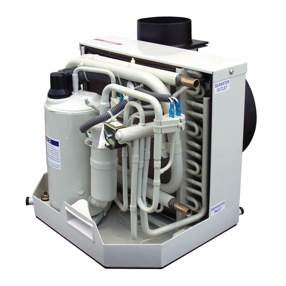
3 Overview 3.1 Outline Drawing 3.2 How It Works Your self-contained air conditioner consists of four main components and a refrigerant gas circulating through the system. The BLOWER draws warm cabin air across the fins on the EVAPORATOR where the heat from the air is transferred to the refrigerant in the evaporator coil. -
Page 7: Outline Dimensions
3.3 Outline Dimensions Units: mm FCF 6,000 BTU 115V FCF 6,000 BTU 230V 91.5 FCF 10,000 BTU 115V FCF 10,000 BTU 230V FCF 12,000 BTU 115V FCF 12,000 BTU 230V FCF 16,000 BTU 115V 119.4 FCF 16,000 BTU 230V FCF 20,000 BTU 230V... -
Page 8: Installation
4 Installation 4.1 Unpacking and Inspection When the equipment is received, all items should be carefully checked to ensure there is no damage from shipping. Move units in the normal "up" orientation as indicated by the arrows on each carton. Examine by removing the units from the cartons if necessary. -
Page 9: The Size Of Sealed Room
4.3 The size of sealed room The size of sealed room should not be too small; otherwise it will affect the unit normal functionality. See diagram below. 4.4 Placement of System Selecting a good location for your air conditioner is the most important part of your preparation. Be sure to consider the size of the area you are cooling, the air distribution needs, and the size of the unit you have chosen. -
Page 10: Condensate Drains
The unit should be installed as low as possible, BUT NEVER IN THE BILGE OR Tools required: ENGINE ROOM AREAS, ENSURE THAT THE SELECTED LOCATION IS SEALED ◆Screws drivers FROM DIRECT ACCESS TO BILGE AND/OR ENGINE ROOM VAPORS. Installing the unit as low as possible (such as under a V-berth, dinette seat or bottom of a ◆Pliers locker) and ducting the supply air as high as possible, creates an ideal airflow ◆Pipe wrench... -
Page 11: Blower Assembly
Do not terminate condensate drain line within three 3’ (914mm) of any outlet of engine, generator exhaust systems, compartment housing an engine or generator, nor in a bilge, unless the drain is connected properly to a sealed condensate or shower sump pump. Seal all condensate hose penetrations. -
Page 12: Seawater Pump And Plumbing
All ducting should: ◆ Be appropriately sized for each application. ◆ Run as smoothly and taut as possible. ◆ Have as few bends or loops as possible. ◆ Be securely fastened to prevent sagging or chafing during vessel operation. ◆ Have all excess ducting lengths trimmed off. ◆... -
Page 13: Electrical Connections, Grounding And Bonding
4.11 Electrical Connections, Grounding and Bonding All A/C units have a terminal strip mounted inside the electric box. The terminal strip is labeled for proper connections of the electrical supply, ground wires and pump circuits. A wiring diagram is provided in the electrical box and later in this manual. -
Page 14: Manual Controller Installation
1 ) Connections between the vessel's A/C system grounding conductor (green wire) and the vessel’s DC (Direct Current) negative or bonding system should be made as part of the vessel's wiring, per ABYC standard E-9, or equivalent. 2 ) When servicing or replacing existing equipment that contains a chassis-mounted ground stud, the installer must check the vessel's wiring for the existence of the connection required in item 1 above. -
Page 15: Electric Box Installation
4.13 Electric Box Installation 4.13.1 (6K, 10K, 12K, 16K) Mount the electric box using four M5 screws. Mount the electric box in a cool dry location and leave plenty of room for maintenance. Units: mm... - Page 16 4.13.2 (20K, 25K) Units: mm...
-
Page 17: Installation Checklist (Review Prior To Installation)
4.14 Installation Checklist (Review Prior To Installation) 4.14.1 Seawater cooling system: ◆ Speed scoop located as far below the water line and as close to the keel as possible. ◆ Shut off valve (sea cock) and speed scoop properly sealed and tightened. ◆... -
Page 18: Wiring Diagrams
4.15 Wiring Diagrams The following electric diagram is for reference only. Please refer to diagram affixed to the unit as the latest version. WIRING DIAGRAM: 6K-115V, 6K-230V, 10K-115V, 10K-230V The specification of power cord is AWG12*3 (3*2.5). - Page 19 WIRING DIAGRAM: 12K-115V, 12K-230V The specification of power cord is AWG12*3 (3*2.5).
- Page 20 WIRING DIAGRAM: 16K-115V, 16K-230V The specification of power cord is AWG12*3 (3*2.5).
- Page 21 WIRING DIAGRAM: 20K-230V, 25K-230V The specification of power cord is AWG12*3(3*2.5). WIRING DIRGRAM / POWER SUPPLY:...
-
Page 22: Operation
5 Operation 5.1 Manual Controller Operation CAUTION: ◆ Don't install the manual controller in a location where it can get wet. ◆ Don’t knock, throw or open the manual controller frequently. ① Remote receiver (not used with this series) ⑥ Fan control button ②... -
Page 23: Power On/Off
5.2 Power ON/OFF ◆ Press ON/OFF button to turn the unit on ◆ Pressing the ON/OFF button a second time will turn the unit off 5.3 FAN Control ◆ Press the FAN button, the fan speed will change in the following order: ... -
Page 24: Error Codes
5.7 Error Codes When there are faults within the system, an error code will be displayed on the display controller: Power off the unit and contact professional service. Error code Description Compressor high pressure protection Evaporator freezing protection Compressor low pressure protection Communication error Ambient temperature sensor error Evaporator temperature sensor error... -
Page 25: Auto -Off Function Of The Manual Controller
5.11 Auto –off function of the manual controller The display of ambient temperature will automatically blank in 5-minute lag if there is no operation on the manual controller. 1 ) After receiving the signal from the manual controller, the indicator will light on automatically, in which case, the unit will not operation at all and the manual controller can be active after it lights on. -
Page 26: Troubleshooting
7 Troubleshooting FAULT POSSIBLE REASON CORRECTION A/C circuit breaker is off Turn circuit breaker on at ship's panel, See control operation section in this manual. Display control is not turned on. Check wiring Diagram and correct if necessary. Fuse is broken Replaced with a new fuse. - Page 27 FAULT POSSIBLE REASON CORRECTION Reversing valve may be stuck. Tap reversing valve lightly with rubber mallet while No Heating unit is in heat mode, call for service if the problem cannot be solved. Air flow is blocked Remove any obstructions in return air stream, Clean return air filter and grille.
-
Page 28: Maintenance
FAULT POSSIBLE REASON CORRECTION Manual 4-pin display cable plugs are not making With POWER OFF at the circuit breaker, remove controller is not contact (unplugged, dirty, bent, or broken connector and inspect. If damaged, replace connector lit. pins). or entire display cable. Set point temperature is improperly set: Raise or lower set point. -
Page 29: Return Air Filters
This product comes with a 24 month limited warranty from the date of purchase. For warranty policy details, visit http://www.techwebasto.com. To obtain warranty service, contact a customer service representative at: (800) 860-7866 or e-mail at: info-us@webasto.com. 8.8 Technical Assistance If you require help, check our technical assistance website at http://www.techwebasto.com or call the technical support hotline at (800) 860-7866. - Page 30 NOTES...
- Page 31 NOTES...
- Page 32 Webasto Thermo & Comfort N.A., Inc. 15083 North Road Fenton, MI 48430 Technical Assistance Hotline USA: (800) 860-7866 Canada: (800) 667-8900 www.webasto.us www.techwebasto.com Org. 6/25/15 | Rev. 10/2016 | P/N: FCF Platinum Series...
Need help?
Do you have a question about the FCF 6,000 BTU and is the answer not in the manual?
Questions and answers