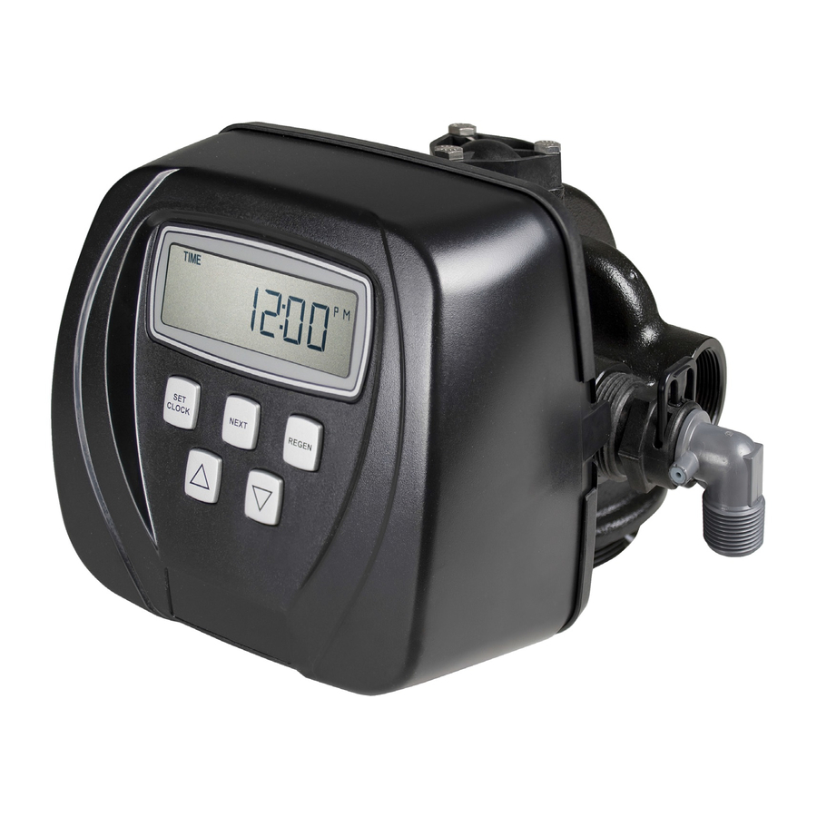
Clack WS1 series Installation, Operation & Maintenance Manual
Simplex nitrate removal unit
Hide thumbs
Also See for WS1 series:
- Installation, operation & maintenance manual (27 pages) ,
- Manual (19 pages) ,
- Installation, operation & maintenance manual (16 pages)
Table of Contents

Related Manuals for Clack WS1 series


Summary of Contents for Clack WS1 series
- Page 1 WS1”, 1.5” & 2” Series NRU Installation Operation Maintenance Manual Installation Operation Maintenance Manual Simplex Nitrate Removal Unit With WS1”, 1.5” & 2” Series Valve Models 20 ltr - 750 ltr Simplex Clack NRU rev 1 Page 1 of 27...
-
Page 2: Table Of Contents
11.1.4 WS2 150-750 L.......................19 11.2 ENGINEERING DATA .....................20 11.2.1 WS1 20-80 L......................20 11.2.2 WS1 100-350 L.......................21 11.2.3 WS1.5 100-500 L....................22 11.2.4 WS2 150-750 L.......................23 12.0 FACTORY PROGRAM........................24 13.0 CE Certificate ..........................27 Simplex Clack NRU rev 1 Page 2 of 27... -
Page 3: Parts List
WS1”, 1.5” & 2” Series NRU Installation Operation Maintenance Manual 1.0 PARTS LIST 1.1 BASIC PARTS LIST 1. Clack VALVE C/W TRANSFORMER 2. VESSEL & RISER 3. BRINE TANK 4. INSTRUCTIONS 5. REDUCER (if required) 6. RESIN 1.2 MISSING OR DAMAGED GOODS Immediately on receipt of the goods, it is advisable to check that all items ordered have been received. -
Page 4: Meter Control Of Regeneration
Where possible this should be installed through an outside wall like a cistern overflow, where it will give a visual indication of any failure. Simplex Clack NRU rev 1 Page 4 of 27... -
Page 5: Operating Space
If the pressure available from the mains is not adequate it will be necessary to install a booster pump arrangement. Such a system would be covered by additional bylaws, and the water storage tank needed must comply with these. Simplex Clack NRU rev 1 Page 5 of 27... -
Page 6: Electrical
Once the vessel is filled, immediately sweep up any spilled resin. Remove cover from distributor tube and brush any beads of resin out of the threads in the neck of the vessel. Simplex Clack NRU rev 1 Page 6 of 27... -
Page 7: Programming
6.2 CONTROLLER SETTING - Site programming mode All controller settings will require the valve to have the mains supply switched on. The valve must not be regenerating when controller settings are adjusted. Simplex Clack NRU rev 1 Page 7 of 27... -
Page 8: Setting The Time Of Day
300ppm and a reserve capacity of 33%. This may need to be altered based on local water nitrate and sulphate and reserve required for the site (see section 13.1) The time of day for Simplex Clack NRU rev 1 Page 8 of 27... -
Page 9: Factory Programming
NEXT Set 4 cycle time in minutes – FAST RINSE NEXT Set 5 cycle time in kilos of salt required per regeneration – BRINE REFILL except WS2 which is in minutes Simplex Clack NRU rev 1 Page 9 of 27... - Page 10 ” keys To back up at any stage – Press “REGEN” To save any changes – Press “SET CLOCK” Press together and hold for 5 seconds Set Influent Nitrate and sulphate in ppm if NEXT metered, nA if timeclock Simplex Clack NRU rev 1 Page 10 of 27...
- Page 11 WS1”, 1.5” & 2” Series Waternru Installation Operation Maintenance Manual Set effluent nitrate and sulphate in ppm if mixing valve fitted, if no mixing valve fitted then set to 0 if NEXT metered. NA if timeclock. Set day regeneration override for metered nru’s OR set frequency of regenerations for Timeclock valves NEXT (1-28 days)
-
Page 12: Commisioning
WS1”, 1.5” & 2” Series Waternru Installation Operation Maintenance Manual 7.0 COMMISIONING The objective of commisioning is to fill the nru and brine tank with water, check for leaks and prepare it for service. The simplest way to commission the unit is to initiate a regeneration. This will eliminate the air from the system and flush the resin prior to use. -
Page 13: Routine Monitoring
WS1”, 1.5” & 2” Series nru Installation Operation Maintenance Manual 8.0 ROUTINE MONITORING The following recommendations are made to help the user of the nru confirm that it is performing as required, and to give early warning of possible problems. The operation of the nru is completely automatic, and should not require adjustment. -
Page 14: Fault Finding And Rectification
WS1”, 1.5” & 2” Series nru Installation Operation Maintenance Manual 9.0 FAULT FINDING AND RECTIFICATION Modern Nitrate Removal Unit are extremely reliable and unlikely to give any problems if they are installed and operated correctly. 9.1 NO FLOW TO SERVICE Check mains pressure is above 1.7 bar. -
Page 15: No Regeneration
WS1”, 1.5” & 2” Series nru Installation Operation Maintenance Manual 9.3 NO REGENERATION Check electrical supply, fuses etc. satisfactory. Check control head motor runs by initiating a manual regeneration (Press “REGEN” button for 5s and then again for a further 5s), listening for drive motor ‘whirring' as it advances between cycles. -
Page 16: Technical Data
WS1”, 1.5” & 2” Series nru Installation Operation Maintenance Manual 11.0 Technical Data 11.1 Process and Operating Data 11.1.1 WS1 20-80 L PARAMETER UNITS MAX.SERVICE M3/hr FLOW SYSTEM 1.25 CAPACITY CaCO3 CAPACITY @ 6.25 12.5 200PPM SALT USED 6.25 12.5 PER REGEN SALT STORAGE... -
Page 17: Ws1 100-350 L
WS1”, 1.5” & 2” Series nru Installation Operation Maintenance Manual 11.1.2 WS1 100-350 L PARAMETER UNITS 100L 120L 150L 250L 350L MAX.SERVICE M3/hr FLOW SYSTEM 12.5 17.5 CAPACITY CaCO3 CAPACITY @ 37.5 62.5 87.5 200PPM SALT USED 37.5 62.5 87.5 PER REGEN SALT STORAGE... -
Page 18: Ws1.5 100-500 L
WS1”, 1.5” & 2” Series nru Installation Operation Maintenance Manual 11.1.3 WS1.5 100-350 L PARAMETER UNITS 100L 120L 150L 250L 350L MAX.SERVICE M3/hr 11.6 FLOW SYSTEM 12.5 17.5 CAPACITY CaCO3 CAPACITY @ 37.5 62.5 87.5 200PPM SALT USED 37.5 62.5 87.5 PER REGEN SALT... -
Page 19: Ws2 150-750 L
WS1”, 1.5” & 2” Series nru Installation Operation Maintenance Manual 11.1.4 WS2 150-750 L PARAMETER UNITS 150L 200L 250L 300L 350L 500L 750L MAX.SERVICE M3/hr FLOW SYSTEM 12.5 17.5 37.5 CAPACITY CaCO3 CAPACITY @ 37.5 62.5 87.5 187.5 200PPM SALT USED 37.5 62.5 87.5... -
Page 20: Engineering Data
WS1”, 1.5” & 2” Series nru Installation Operation Maintenance Manual 11.2 ENGINEERING DATA 11.2.1 WS1 20-80 L PARAMETER UNITS VESSEL SIZE INCH 9x35 10x35 10x44 10x54 12x48 13x54 BRINE TANK 1040 HEIGHT BRINE TANK WIDTH 370 x 370 x TOTAL HEIGHT 1100 1100 1390... -
Page 21: Ws1 100-350 L
WS1”, 1.5” & 2” Series nru Installation Operation Maintenance Manual 11.2.2 WS1 100-350 L PARAMETER UNITS 100L 120L 150L 250L 350L VESSEL SIZE INCH 14x65 14x65 16x65 21x62 24x72 BRINE TANK 1100 1250 HEIGHT BRINE TANK WIDTH TOTAL HEIGHT 1984 1984 1988 2038... -
Page 22: Ws1.5 100-500 L
WS1”, 1.5” & 2” Series nru Installation Operation Maintenance Manual 11.2.3 WS1.5 100-500 L PARAMETER UNITS VESSEL SIZE INCH 14x65 14x65 16x65 21x62 24x72 BRINE TANK 1100 1250 HEIGHT BRINE TANK WIDTH TOTAL HEIGHT 1984 1984 1988 2038 2225 REAR CLEARENCE REQUIRED INLET CONNS INCH... -
Page 23: Ws2 150-750 L
WS1”, 1.5” & 2” Series nru Installation Operation Maintenance Manual 11.2.4 WS2 150-750 L PARAMETER UNITS VESSEL SIZE INCH 16x65 21x62 21x62 24x72 24x72 30x72 36x72 BRINE TANK 1100 1100 1250 1315 1520 HEIGHT BRINE TANK 1190 1350 WIDTH TOTAL 2098 2098 2098... -
Page 24: Factory Program
WS1”, 1.5” & 2” Series nru Installation Operation Maintenance Manual 12.0 FACTORY PROGRAM To enter press Next and down for 5 seconds Screen Entered Value Explanation Softening Softening Valve 1 Backwash 25 4 Backwash time against resin 30 4 volumes 40 4 50 6 60 6... - Page 25 WS1”, 1.5” & 2” Series nru Installation Operation Maintenance Manual 30 4 volumes 40 4 50 6 60 6 80 6 100 8 120 8 150 8 200 10 250 10 300 10 350 10 500 10 750 10 5 Fill 25 6.3 30 7.5 40 10...
- Page 26 WS1”, 1.5” & 2” Series nru Installation Operation Maintenance Manual used up SALT SIMPWS1 REV2 06/08/10 PAGE 26 OF27...
-
Page 27: Ce Certificate
Manufacturer's Declaration of Conformity We the undersigned EURAQUA UK, HITCHIN, ENGLAND Certify that the product type: SIMPLEX WATER NRU WITH CLACK WS1, 1.5 or 2” 12 VOLT AC VALVE has been designed and manufactured in accordance with the specifications of the following:...
Need help?
Do you have a question about the WS1 series and is the answer not in the manual?
Questions and answers
The unit keeps overflowing during regeneration
The Clack WS1 series unit may be overflowing during regeneration due to one or more of the following reasons:
1. Incorrect Drain Flow – The total flow to drain is about six times the resin volume, and if the drain line is restricted or improperly sized, it may cause overflow.
2. Blocked or Faulty Valve – A malfunctioning or clogged valve could prevent proper flow control during regeneration.
3. Improper Programming – If the regeneration cycle settings are incorrect, excessive water may be used.
4. Bypass or MAV/NHWBV Issue – If the Motorized Alternating Valve (MAV) or No Hard Water Bypass Valve (NHWBV) is not functioning correctly, it may allow water to flow improperly.
5. High Inlet Pressure – The inlet pressure affects flow rates, and excessive pressure may cause overflow.
Checking these factors and ensuring proper installation, programming, and maintenance should help resolve the issue.
This answer is automatically generated