Table of Contents
Advertisement
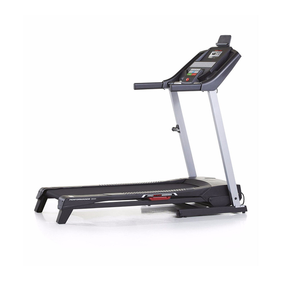
Model No. PETL59816.0
Serial No.
Write the serial number in the space
above for reference.
Serial
Number
Decal
CUSTOMER SERVICE
UNITED KINGDOM
Call: 0330 123 1045
From Ireland: 053 92 36102
Website: www.iconsupport.eu
E-mail: csuk@iconeurope.com
Write:
ICON Health & Fitness, Ltd.
Unit 1D, The Gateway
Fryers Way, Silkwood Park
OSSETT
WF5 9TJ
UNITED KINGDOM
AUSTRALIA
Call: 1800 993 770
E-mail: australiacc@iconfitness.com
Write:
ICON Health & Fitness
PO Box 635
WINSTON HILLS NSW 2153
AUSTRALIA
CAUTION
Read all precautions and instruc-
tions in this manual before using
this equipment. Save this manual
for future reference.
USER'S MANUAL
www.iconeurope.com
Advertisement
Table of Contents

Related Manuals for Pro-Form Performance 300i PETL59816.0


Summary of Contents for Pro-Form Performance 300i PETL59816.0
- Page 1 Model No. PETL59816.0 USER’S MANUAL Serial No. Write the serial number in the space above for reference. Serial Number Decal CUSTOMER SERVICE UNITED KINGDOM Call: 0330 123 1045 From Ireland: 053 92 36102 Website: www.iconsupport.eu E-mail: csuk@iconeurope.com Write: ICON Health & Fitness, Ltd. Unit 1D, The Gateway Fryers Way, Silkwood Park OSSETT...
-
Page 2: Table Of Contents
TABLE OF CONTENTS WARNING DECAL PLACEMENT ............. . .2 IMPORTANT PRECAUTIONS . -
Page 3: Important Precautions
IMPORTANT PRECAUTIONS WARNING: To reduce the risk of burns, fire, electric shock, or injury to persons, read all important precautions and instructions in this manual and all warnings on the treadmill before using the treadmill. ICON assumes no responsibility for personal injury or property damage sustained by or through the use of this product. - Page 4 21. The treadmill is capable of high speeds. 26. Do not change the incline of the treadmill by Adjust the speed in small increments to placing objects under the treadmill. avoid sudden jumps in speed. 27. Never insert any object into any opening on 22.
-
Page 5: Before You Begin
BEFORE YOU BEGIN Thank you for selecting the new PROFORM reading this manual, please see the front cover of this ® PERFORMANCE 300I treadmill. The PERFORMANCE manual. To help us assist you, note the product model 300I treadmill offers a selection of features designed number and serial number before contacting us. -
Page 6: Part Identification Chart
PART IDENTIFICATION CHART Use the drawings below to identify small parts used for assembly. The number in parentheses below each draw- ing is the key number of the part, from the PART LIST near the end of this manual. The number following the key number is the quantity used for assembly. -
Page 7: Assembly
ASSEMBLY • Assembly requires two persons. • To identify small parts, see page 6. • Place all parts in a cleared area and remove the • Assembly requires the following tools: packing materials. Do not dispose of the packing the included hex keys materials until you finish all assembly steps. -
Page 8: Assembly
3. Tighten a 3/8" x 2 1/4" Screw (81) and a 3/8" x 3/4" Screw (2) into the Base (36) and into the Right Upright (84) as shown; do not fully tighten the Screws yet. Repeat this step on the left side of the tread- mill. -
Page 9: Sole Assembly (B) Near The Right Handrail (86
6. IMPORTANT: To avoid damaging the Pulse Crossbar (97), do not use power tools and do not overtighten the #10 x 3/4" Screws (80). Orient the Pulse Crossbar (97) as shown. Attach the Pulse Crossbar to the Left and Right Handrails (69, 86) with four #10 x 3/4"... - Page 10 8. Attach the console assembly (B) with ten #8 x 3/4" Screws (79); start all ten Screws, and then tighten them. Make sure that no wires are pinched. Next, insert the wires into the console assem- bly (B). Then, tighten the three Wire Ties (75) around the wires and cut off the ends of the Wire Ties.
- Page 11 10. Remove the M8 Nut (39) and the M8 x 35mm Bolt (7) from the bracket on the Base (36). Next, orient the Storage Latch (42) as shown. Attach the lower end of the Storage Latch (42) to the bracket on the Base (36) with the M8 x 35mm Bolt (7) and the M8 Nut (39).
- Page 12 12. Slide the Right Inner Upright Cap (105) between the Right Upright (84) and the Motor Hood (56). Then, press the Right Outer Upright Cap (106) against the Right Inner Upright Cap until they snap together. Repeat this step on the left side of the tread- mill with the Left Outer and Inner Upright Caps (103, 104) (not shown).
-
Page 13: How To Use The Treadmill
HOW TO USE THE TREADMILL HOW TO PLUG IN THE POWER CORD Follow the steps below to plug in the power cord. This product must be earthed. If it should malfunc- 1. Plug the indicated end of the power cord into the tion or break down, earthing provides a path of least socket on the treadmill. - Page 14 CONSOLE DIAGRAM FEATURES OF THE CONSOLE To turn on the power, see page 15. To use the man- ual mode, see page 15. To use an onboard workout, see page 17. To use an interval training workout, The treadmill console offers a selection of features designed to make your workouts more effective and see page 18.
- Page 15 HOW TO TURN ON THE POWER HOW TO USE THE MANUAL MODE IMPORTANT: If the treadmill has been exposed to 1. Insert the key into the console. cold temperatures, allow it to warm to room tem- perature before you turn on the power. If you do See HOW TO TURN ON THE POWER at the left.
- Page 16 4. Change the incline of the treadmill as desired. 6. Measure your heart rate if desired. To change the incline of the treadmill, press the You can measure your heart rate using either the Incline increase and decrease buttons or one of the handgrip heart rate monitor or a compatible heart rate monitor.
- Page 17 7. When you are finished exercising, remove the Each workout is divided into segments. One speed key from the console. setting and one incline setting are programmed for each segment. Note: The same speed setting and/ Step onto the foot rails, press the Stop button or incline setting may be programmed for consecu- repeatedly, and adjust the incline of the treadmill tive segments.
- Page 18 HOW TO USE AN INTERVAL TRAINING WORKOUT 5. Follow your progress with the displays. During an interval training workout, you will repeatedly See step 5 on page 16. The display will show the alternate between intervals of low-intensity “recovery” time remaining instad of the elapsed time. exercise and intervals of high-intensity “work”...
- Page 19 HOW TO CONNECT YOUR HEART RATE MONITOR When a connection is established, the LED on the console will flash blue. Press the Bluetooth button TO THE CONSOLE on the console to confirm the connection; the LED on the console will then turn solid blue. The console is compatible with all BLUETOOTH Smart heart rate monitors.
- Page 20 THE INFORMATION MODE HOW TO USE THE TABLET HOLDER The console features an information mode that keeps You can use your track of treadmill usage information and allows you to tablet to browse Tablet select a unit of measurement for the console. media while you Holder exercise.
-
Page 21: How To Fold And Move The Treadmill
HOW TO FOLD AND MOVE THE TREADMILL HOW TO FOLD THE TREADMILL HOW TO MOVE THE TREADMILL Before folding the treadmill, remove the key and Before moving the treadmill, fold it as described at the unplug the power cord. CAUTION: You must be left. -
Page 22: Maintenance And Troubleshooting
MAINTENANCE AND TROUBLESHOOTING MAINTENANCE c. Check the power switch located on the treadmill frame near the power cord. If the switch protrudes Regular maintenance is important for optimal per- as shown, the switch has tripped. To reset the formance and to reduce wear. Inspect and properly power switch, wait for five minutes and then press tighten all parts each time the treadmill is used. - Page 23 Remove the six indicated M4.2 x 19mm Screws Locate the Reed Switch (100) and the Magnet (91) (3) and the six Foot Rail Washers (25). Next, on the left side of the Pulley (46). Turn the Pulley lower the Frame (50) (see HOW TO LOWER THE until the Magnet is aligned with the Reed Switch.
- Page 24 SYMPTOM: The walking belt is off-center. b. If the walking belt is overtightened, treadmill per- formance may decrease and the walking belt may IMPORTANT: The walking belt should be centered become damaged. Remove the key and UNPLUG between the foot rails. If the walking belt rubs THE POWER CORD.
-
Page 25: Exercise Guidelines
EXERCISE GUIDELINES Burning Fat—To burn fat effectively, you must exer- WARNING: cise at a low intensity level for a sustained period of Before beginning this time. During the first few minutes of exercise, your or any exercise program, consult your physi- body uses carbohydrate calories for energy. -
Page 26: Part List
PART LIST Model No. PETL59816.0 R0216A Key No. Qty. Description Key No. Qty. Description 3/8" x 2 3/4" Screw Right Idler Roller Bracket 3/8" x 3/4" Screw Right Rear Foot M4.2 x 19mm Screw Left Rear Foot 5/16" x 3/4" Screw Idler Roller M4.2 x 13mm Washer Head Screw Left Idler Roller Bracket... - Page 27 Key No. Qty. Description Key No. Qty. Description Grommet Receptacle M10 External Star Washer Filter Left Outer Upright Cap Motor Isolator Left Inner Upright Cap M4.2 x 13mm Tek Screw Right Inner Upright Cap M10 Washer Right Outer Upright Cap 1/4"...
-
Page 28: Exploded Drawing
EXPLODED DRAWING A Model No. PETL59816.0 R0216A... - Page 29 EXPLODED DRAWING B Model No. PETL59816.0 R0216A 23 11...
- Page 30 EXPLODED DRAWING C Model No. PETL59816.0 R0216A...
- Page 31 EXPLODED DRAWING D Model No. PETL59816.0 R0216A...
-
Page 32: Ordering Replacement Parts
ORDERING REPLACEMENT PARTS To order replacement parts, please see the front cover of this manual. To help us assist you, be prepared to provide the following information when contacting us: • the model number and serial number of the product (see the front cover of this manual) •...
Need help?
Do you have a question about the Performance 300i PETL59816.0 and is the answer not in the manual?
Questions and answers