Table of Contents
Advertisement
Quick Links
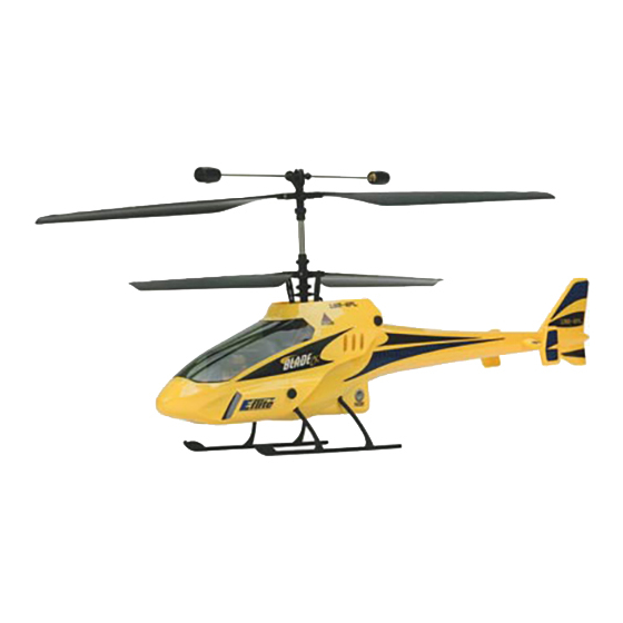
Specifications
Length . . . . . . . . . . . . . . . . . . . . . . . 15.75 in (400mm)
Height . . . . . . . . . . . . . . . . . . . . . . . 7.17 in (182mm)
Main Rotor Diameter . . . . . . . . . . . . . 13.60 in (345mm)
Weight RTF w/Battery . . . . . . . . . . . . 8.0 oz (227 g)
Main Motor . . . . . . . . . . . . . . . . . . . . 180 (2 installed)
Battery . . . . . . . . . . . . . . . . . . . . . . . 7.4V 800mAh Li-Po (included)
Transmitter . . . . . . . . . . . . . . . . . . . . FM 4-Channel (included)
On-Board Electronics . . . . . . . . . . . . . 4-in-1 Receiver/Mixer/ESC/Gyro (installed)
Servo . . . . . . . . . . . . . . . . . . . . . . . . EFLRS75 High-Speed, High-Torque (2 installed)
Advertisement
Table of Contents

Related Manuals for Blade CX


Summary of Contents for Blade CX
-
Page 1: Specifications
Specifications Length ..... . . 15.75 in (400mm) Height ..... . . 7.17 in (182mm) Main Rotor Diameter . -
Page 2: Table Of Contents
15 minutes per charge. While the Blade CX is nearly ready-to-fly right from the box, please take the time to read through this manual completely for tips on battery safety and charging, control checks, flying and more. Please also take a few minutes to watch the included Instructional Video CD for additional tips and to see the Blade CX in action. -
Page 3: Warning
RC applications. All manufacturer’s instructions and warnings must be followed closely. Mishandling of Li-Po batteries can result in fire. Additional Required Equipment Only 8 “AA” batteries (sold separately) are required to complete your Blade™ CX. Blade CX RTF Contents Item... -
Page 4: Warranty Information
By handling, charging or using the included Li-Po battery you assume all risks associated with lithium batteries. If you do not agree with these conditions, return your complete Blade CX model in new, unused condition to the place of purchase immediately. - Page 5 • Do not over-discharge the battery. Discharging the battery too low can cause damage to the pack resulting in reduced performance and duration. Follow the additional guidelines found in the “Flying the Blade CX” section (page 25) to prevent over-discharge of the battery.
- Page 6 Please familiarize yourself thoroughly with the warnings and guidelines (pages 4–5) before continuing. Note: The Li-Po battery pack included with your Blade™ CX will arrive partially charged. For this reason the initial charge may only take approximately 1.0–1.5 hours.
- Page 7 Battery Warnings, Guidelines and Charging (continued) Input power for the charger can also be supplied through the use of an AC to DC adapter/power supply for convenient charging anywhere an AC outlet is available. We recommend the optional E-flite™ AC to 12V DC, 1.5 Amp Power Supply (EFLC4000).
- Page 8 When the battery is properly connected and charging normally, the red and green LED indicators will glow solid. Once the battery has been fully charged, the green LED will go out, leaving just the red LED glowing solid. The battery can now be removed from the charger and installed into the Blade™ CX for flight.
-
Page 9: Charge Errors And Indications
(For more information on preventing over-discharge of the Li-Po battery pack, see the “Flying the Blade CX” section found on page 25), or that a single cell or even both cells in the battery pack may be damaged. -
Page 10: Installing The Flight Battery
Installing the Flight Battery Use the included hook and loop material for mounting the Li-Po battery pack. The “hook” material is already installed on the battery frame stop. Install the “loop” material on the end of the battery with the wire leads. The battery can be installed through the opening in the rear of the body. -
Page 11: Center Of Gravity
Installing the Flight Battery (continued) Quick Tip: You can install a tape “pull tab” on the end of the battery to make it easier to remove. You can also carefully remove some additional material from the opening in the rear of the body. Center of Gravity Once the battery has been properly installed and secured you will need to check the helicopter’s center of gravity. -
Page 12: Control Test
Control Test Although each Blade™ CX model is test flown at the factory, it is a good idea to test the controls prior to the first flight to ensure none of the servos, linkages or other parts were damaged during shipping and handling. Before proceeding, disconnect both of the main motor plugs from the 4-in-1 control unit, making note of their direction and polarities for proper re-installation after the control test is complete. - Page 13 Control Test (continued) Position the helicopter to view it from the left-hand side. Move the right-hand control stick on the transmitter forward and back to check elevator pitch control. When the stick is pushed forward, the rear servo should push the swashplate upward. When the stick is pulled back, the rear servo should pull the swashplate downward.
- Page 14 Once you have confirmed that the servo connection locations are correct, all controls should be functioning properly. If you do encounter any problems with your Blade CX responding properly to the transmitter, do not fly. Contact Horizon Hobby’s Product Support staff at 1-877-504-0233.
-
Page 15: 4-In-1 Control Unit Description, Arming And Motor Control Test
4-in-1 Control Unit Description, Arming and Motor Control Test The unique 4-in-1 Control Unit installed on your Blade™ CX is a lightweight combination of 4-channel FM receiver, main motor mixer, main motor electronic speed controls, and piezo gyro. The 4-in-1 unit also contains a main motor proportional mix trimmer pot and status LED. - Page 16 4-in-1 Control Unit Description, Arming and Motor Control Test (continued) Elevator Trim Throttle Trim Set Throttle Trim and Throttle Stick at Lowest Position Aileron Trim Rudder Trim • After confirming that the transmitter has been turned on and has an adequate level of battery power as displayed by the LEDs at the top of the transmitter, it is now safe to connect the flight battery to the 4-in-1 unit.
- Page 17 Next, move the rudder stick all the way to the left. This should cause the speed of the lower main rotor blade to increase and the speed of the upper main rotor blade to decrease.
-
Page 18: Before The First Flight
Before the First Flight If the Blade™ CX is your first helicopter model, we suggest that you install the optional Training Gear Set (EFLH1205) before making your first flight. The training gear helps to further increase the stability of the model while also providing added support and cushioning to prevent tip-overs and damage to the model from abrupt landings. - Page 19 Before the First Flight (continued) • Once you have installed all four attachments, install the four screws making sure that they thread properly into the back side of the attachment. It may be helpful to squeeze the attachment with a pair of pliers to make it easier to thread the screw into the backside of the attachment.
- Page 20 • Adjust the position of the tubing keepers and plastic balls on the training gear rods so that the balls are positioned approximately 1/8” from the end of each rod. Be sure that the tubing keepers are positioned so that the plastic ball can still spin freely on the rod. Your Blade™ CX is now ready for flight.
- Page 21 Before the First Flight (continued) If you are not familiar with the controls of the helicopter, please take a few minutes to familiarize yourself with them before attempting your first flight. The left-hand stick controls both throttle (ascend/descend) and rudder (yaw left/right). When the throttle is in the lowest position the main rotor blades will not spin.
- Page 22 This is accomplished by increasing the speed of the lower main rotor blade while decreasing the speed of the upper main rotor blade. Moving the stick to the right will turn (yaw) the nose of the helicopter to the to the right about the axis of the main shaft.
- Page 23 Before the First Flight (continued) Moving the stick to the left will roll the helicopter to the left, allowing the helicopter to be flown to the left. Moving the stick to the right will roll the helicopter to the right, allowing the helicopter to be flown to the right. The aileron trim can be used to help keep the helicopter from drifting left or right when in hover with no aileron stick input.
-
Page 24: Flying The Blade™ Cx
At these higher altitudes you will be able to get a feel for the flight characteristics of the Blade CX when it is flying out of “ground effect.”... - Page 25 • I n the unfortunate event of a crash or rotor blade strike, no matter how minor or major, you MUST lower both the throttle stick and throttle trim to their lowest possible position as quickly as possible to prevent damage to the ESCs of the 4-in-1 unit.
-
Page 26: Main Motor Proportional Mix Trimmer Pot Description And Adjustment
If the nose of the helicopter is drifting to the left, you will want to increase power to the right-hand motor (spinning the upper main rotor blade). This is accomplished by turning the “proportional”... -
Page 27: Upper Main Rotor Blade Tracking Adjustment
• You can check the upper main rotor blade tracking either on the ground or in the air at eye level. It might be a good idea to have an assistant on hand to help sight the blade tracking. - Page 28 Don’t worry as the helicopter will still perform well as long as the blade tracking is adjusted as closely as possible. Note: It will not be necessary to adjust the Lower Main Rotor Blade tracking as fixed links are used between the rotor blade and swashplate.
-
Page 29: Main Motor Care And Installing The Optional Main Motor Heat Sink
Main Motor Care and Installing the Optional Main Motor Heat Sink The 180 motors used to power your Blade™ CX are of the closed end-bell variety and do not require any special maintenance. We do, however, suggest that you allow the motors to cool to near ambient temperature between flights/battery pack changes to prevent accelerated motor wear due to excess motor heat. - Page 30 Main Motor Care and Installing the Optional Main Motor Heat Sink (continued) • You can now press the right-hand main motor into place in the heat sink and use the motor mounting screws to re-install the motor on the main frame. Again, we recommend that you use Heat Sink Compound (EFLM1913) on any surfaces of the heat sink that make contact with the motor case to further improve the effectiveness of the heat sink.
-
Page 31: 2005 Official Ama National Model Aircraft Safety Code
2005 Official AMA National Model Aircraft Safety Code GENERAL 1) I will not fly my model aircraft in sanctioned events, air shows or model flying demonstrations until it has been proven to be airworthy by having been previously, successfully flight tested. 2) I will not fly my model higher than approximately 400 feet within 3 miles of an airport without notifying the airport operator. -
Page 32: Replacement Parts List
Replacement Parts List EFLH1200 ..... Blade CX RTF Electric Coaxial Heli EFLB0990 ..... 7.4V 800mAh 2-Cell Li-Po, JST/Balance EFLC3100 . -
Page 33: Replacement And Optional Parts
Swashplate Set: BCX Lower Rotor Head & Linkage Set: BCX EFLH1121 EFLH1214 EFLH1215 EFLH1216 EFLH1217 Lower Main Blade Set Upper Main Blade Set Servo Pushrod Set: BCX Stabilizer Flybar Set: BCX Landing Skid Set: BCX (2 pair): BCX (2 pair): BCX... -
Page 34: Exploded View Parts Listing
013....M2 x 2.5mm Screw (5) ....EFLH1225 014....Lower Main Blade (2) ....EFLH1220 015. -
Page 35: Exploded View
Exploded View... - Page 36 © 2005 Horizon Hobby, Inc. 4105 Fieldstone Road Champaign, Illinois 61822 (877) 504-0233 www.E-fliteRC.com 8365...
Need help?
Do you have a question about the CX and is the answer not in the manual?
Questions and answers