Table of Contents
Advertisement
Available languages
Available languages
TRONCATRICE CIRCOLARE
MITRE-SAW
KREISSÄGE
SCIE A ONGLET
TRONZADORA
SERRA CIRCULAR
CERTIFICATA
CERTIFIED
GEPRÜFT
CERTIFIE
CERTIFICADA
CERTIFICADA
art. XXX
art. XXX-ALU
ISTRUZIONI PER L’USO E MANUTENZIONE
INSTRUCTIONS FOR USE AND MAINTENANCE
GEBRAUCHSANLEITUNGEN UND WARTUNG
MODE D’EMPLOI ET ENTRETIEN
INSTRUCCIONES PARA EL USO Y MANUTENCION
INSTRUÇÕES DE UTILIZAÇÃO
www.femi.it
Advertisement
Chapters
Table of Contents

Related Manuals for Femi XXX


Summary of Contents for Femi XXX
- Page 1 TRONZADORA SERRA CIRCULAR CERTIFICATA CERTIFIED GEPRÜFT CERTIFIE CERTIFICADA CERTIFICADA art. XXX art. XXX-ALU ISTRUZIONI PER L’USO E MANUTENZIONE INSTRUCTIONS FOR USE AND MAINTENANCE GEBRAUCHSANLEITUNGEN UND WARTUNG MODE D’EMPLOI ET ENTRETIEN INSTRUCCIONES PARA EL USO Y MANUTENCION INSTRUÇÕES DE UTILIZAÇÃO www.femi.it...
- Page 2 DICHIARAZIONE DI CONFORMITÁ CE DEL COSTRUTTORE FEMI S.p.A. Via del Lavoro, 4 - 40023 Castel Guelfo (BO) - ITALIA Tel. +39-0542-670160 - Fax +39-0542-670185 - http://www.femi.it Dichiara sotto la nostra esclusiva responsabilità che questa macchina è conforme alle disposizioni della Direttiva Macchine 98/ 37/CE ed è...
- Page 4 SCHEMA ELETTRICO / WIRING DIAGRAM / ELEKTRISCHER SCHALTPLAN - / SCHEME ELECTRIQUE / ESQUEMA ELECTRICO / ESQUEMA ELÉCTRICO Motore Motor Motor Moteur Motor Motor Condensator Condensatore Condensador Condensador Kondensator Condensateur Pulsante di marcia Start switch Pulsador de marica Botão de arranque Handschalter Bouton marche Connettori Faston...
-
Page 5: Table Of Contents
INDICE INTRODUZIONE ALL’USO ........5 2 INSTALLAZIONE ............7 3 REGOLAZIONI ............8 4 UTILIZZAZIONE ............8 5 ACCESSORI ............10 6 MANUTENZIONE ........... 10 7 GUIDA ALLA LOCALIZZAZIONE DEI GUASTI ..11 Questi simboli e note sono di tre categorie identificati nelle INTRODUZIONE ALL’USO parole: Prima di iniziare le lavorazioni con la Vostra troncatrice,... - Page 6 TIPO DI IMPIEGO E CONTROINDICAZIONI Salvaguardatevi dal’elettrificazione: evitate contatti con oggetti con messa a terra, come tubi, termosifoni La troncatrice circolare è stata progettata e realizzata con e frigoriferi. l’impiego delle più avanzate tecnologie, ed è in grado di soddisfare tutte le esigenze di taglio di legno, alluminio e NORME DI SICUREZZA PER I RISCHI materie plastiche tipiche del professionista, dell’artigiano e RESIDUI...
-
Page 7: Installazione
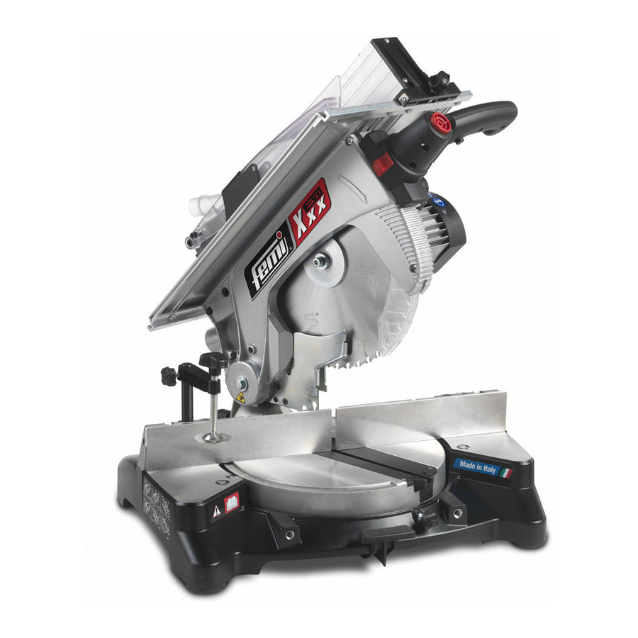
DESCRIZIONE DELLA MACCHINA (Fig.1) sovrapposizione di più scatole. Per quanto possibile, è buona norma fissare il carico con La troncatrice circolare è composta da tre parti fondamentali: corde o cinghie di sicurezza, per evitare spostamenti e il corpo centrale , comprendente il motore 6, che è collegato cadute del carico durante il trasporto. -
Page 8: Regolazioni
Per montare il carter, con la testa sollevata, inseritelo sugli REGOLAZIONI appoggi angolari 33 della base, dopo di che abbassate di nuovo la testa e bloccate il corpo in questa posizione ATTENZIONE: Tutte le operazioni di regolazione tramite il perno di bloccaggio 19. Per regolare l’altezza del illustrate nei paragrafi seguenti devono essere piano superiore, in modo da effettuare il taglio dello spessore effettuate con motore della macchina spento. - Page 9 MONTAGGIO E/O SOSTITUZIONE DELLA USO COME SEGA CIRCOLARE LAMA (Fig. 11) (taglio sul piano superiore) (Fig. 10) ATTENZIONE: Effettuate queste operazioni solamente dopo avere fermato il motore della ATTENZIONE: Lavorando sul piano superiore, è macchina rilasciando il pulsante di marcia 2 necessario montare il carter di protezione dell’interruttore.
-
Page 10: Accessori
ASPIRAZIONE DELLE POLVERI (Fig.14) ACCESSORI (OPTIONAL) SCELTA DELLA LAMA La troncatrice e’ predisposta per il collegamento con un aspiratore, o per il montaggio del sacchetto raccogli polvere, La troncatrice e’ dotata di serie di lama al WIDIA tramite il collettore di scarico 13. (diametro 305 x foro 30 x spessore 2,5 mm). -
Page 11: Guida Alla Localizzazione Dei Guasti
essere conferita ad un Centro di raccolta e smaltimento SMALTIMENTO dei rifiuti autorizzato al fine di rispettare le Norme per MACCHINA, l’igiene e la salvaguardia dell’ambiente. IMBALLAGGIO Anche l’imballaggio va smaltito secondo le normative Quando si rende necessario, alla fine vigenti, conferendolo a soggetti autorizzati alla raccolta ed del normale ciclo di funzionamento, allo smaltimento o al recupero. - Page 12 INDEX INTRODUCTION TO USE ........12 2 INSTALLATION ............13 3 ADJUSTMENT ............15 4 USE ................ 15 5 ACCESSORIES ............17 6 MAINTENANCE ............17 7 TROUBLESHOOTING ........... 18 HAZARD: high risk behaviour which could be INTRODUCTION TO USE severely harmful.
- Page 13 RECOMMENDED AND NOT RACCOMENDED SAFETY PROCEDURE FOR FURTHER RISKS – Do not force the machine unnecessarily: excessive The most advanced technologies have been used to design cutting pressure may lead to rapid deterioration of the and manufacture the mitre-saw. It is suitable to cut wood, blade and a decrease in performance in terms of aluminium and plastics used by professionals, craftsmen finish and cutting precision.
- Page 14 MACHINE DESCRIPTION (Fig.1) POSITION/WORK STATION (Fig. 2-3) The mitre-saw machine consists of three basic parts : the Place the machine on a work bench or on a sufficiently flat machine body complete with motor 6 which is integrated base/ pedestal to ensure the best possible stability. Should into lower part 3 by means of the joint 4 and the swivel you wish to attach the machine to a workbench, you will support 5, and the upper work unit consisting of the work...
- Page 15 ADJUSTING (Fig. 4-5-6-7-8) To install the safety guard with the head uplifted, place it on the angular bearings 33 of the base. Then lower the HAZARD: All the adjustment procedures head and block the body in this position by means of the illustrated below must be performed when the block pin 19.
- Page 16 USE AS A CIRCULAR SAW INSTALLATION AND/OR REPLACEMENT OF (cutting on the upper work surface) (Fig. THE BLADE (Fig. 11) HAZARD: This procedure must be carried out HAZARD: When working on the upper surface, only after having turned off the machine’s motor it is absolutely necessary to install the lower by by release the main switch button 2.
- Page 17 SUCTION OF DUST RESIDUES ACCESSORIES (Fig.14) (OPTIONAL) The mitre-saw can be connected to an aspirator or a dust SELECTION OF THE BLADE collection bag can be mounted by means of the exhaust The mitre-saw is fitted with a WIDIA blade (305 diameter manifold 13.
- Page 18 DISPOSAL OF THE MACHINE, PACKING The packing must be disposed of according to the ruling standards by delivering it to authorised people for the At the end of the machine life, if the collection, disposal or reclaim. machine must be scraped, contact Please contact the ASSOCIATION OF USED OILS near to an authorised waste disposal centre you.
-
Page 19: Einführung
INHALT EINFÜHRUNG ........... 19 INSTALLIEREN ..........21 EINSTELLUNGEN ..........22 GEBRAUCH ............22 MASCHINENTEILE ..........24 WARTUNG ............24 STÖRUNGSSUCHE UND - BEHEBUNG ..25 ACHTUNG: gefährliche Verhaltensweisen können EINFÜHRUNG IN DIE BEDIENUNG zu schweren Verletzungen führen. Bevor Sie mit Ihrer Kreissäge zu arbeiten beginnen, lesen VORSICHT: falsche Verhaltensweisen können zu Sie bitte dieses Handbuch aufmerksam durch, bis Sie die mittelschweren Verletzungen oder Sachschäden... - Page 20 ALLGEMEINE SICHERVORSCHRIFTEN SICHERHEITSVORSCHRIFTEN FÜR WEITERE RISIKEN Die Kreissäge wurde unter Verwendung von modernsten technologischen Mitteln entwickelt und hergestellt. Sie Forcieren Sie die Maschine nicht unnötig: zu starker Druck beim Sägen beschädigt das Sägeblatt schnell, entspricht allen einschlägigen Anforderungen, die was zu einer Leistungsverminderung der Maschine bei Facharbeiter, Handwerker, sowie erstklassige Heimwerker der Verarbeitung und in der Schnittgenauigkeit führt.
-
Page 21: Installieren
Wenn möglich, soll die Ladung mit Seilen oder BESCHREIBUNG DER MASCHINE (Abb. 1) Sicherheitsriemen fixiert werden, damit es während des Die drei wichtigsten Teile der Kreissäge sind: das Transports nicht zu Verschiebungen kommt oder Teile der Zentralgehäuse mit dem Motor 6, das durch das Gelenk 4 Ladung sogar herausfallen. -
Page 22: Einstellungen
Zur Montage der Schutzabdeckung bei hochgezogenem Kopf EINSTELLUNGEN muß diese auf die Winkelstützen 33 des Sockels positioniert werden. Danach wird der Kopf wieder heruntergesenkt und ACHTUNG: Bevor Sie eine der in den folgenden das Gehäuse in dieser Position mit dem Blockierungsstift 19 Abschnitten beschriebenen Einstellungsarbeiten fixiert. - Page 23 VERWENDUNG ALS KREISSÄGE Die beiden mitgelieferten Sechskantschlüssel (Schnitt auf der oberen Fläche) (Abb. 10) hervornehmen. Den Schlüssel für 6mm-Sechsecke ins Endelement 38 der Antriebswelle einführen, den ACHTUNG: Wird auf der oberen Fläche für 6 mm-Sechsecke in die Fixierungsschraube des gearbeitet, muß die mitgelieferte untere Sägeblattes 39.
-
Page 24: Maschinenteile
SÄGEMEHLABSAUGUNG (Abb. 14) MASCHINENTEILE (OPTIONAL) WAHL DES SÄGEBLATTES Die Kreissäge ist so gebaut, daß sie an eine Saugvorrichtung angeschlossen werden kann, oder Sägemehlsäcke montiert Die Kreissäge wird serienmäßig mit einem WIDIA- werden können, die durch den Abfallsammler 13 gefüllt Sägeblatt (Durchmesser 305 x Loch 30 x Dicke 2,5) werden.Der Schlauch der Saugvorrichtung oder der Schlauch Auf speziellen Wunsch Sägeblätter erhältlich: des Abfallsackes müssen mit einer Schelle an den... -
Page 25: Störungssuche Und - Behebung
Auch die Verpackung muss entsprechend den einschlägigen STILLEGUNG DER MASCHINE Vorschriften entsorgt und autorisierten Sammel-, Nach Stillegung kann die Maschine als Entsorgungs- bzw. Recyclingstellen übergeben werden. normaler Industriemull entsorgt Wenden Sie sich deshalb an den NÄCHSTEN werden.ENTSORGUNG ENTSORGUNGSFACHBETRIEB FÜR ALTÖL. MASCHINE, VERPACKUNG Wenn die Maschine am Ende eines normalen... - Page 26 INDEX INTRODUCTION A L’EMPLOI ....... 26 INSTALLATION ..........28 REGLAGES ............. 29 UTILISATION ........... 29 ACCESSOIRES ..........31 MAINTENANCE ..........31 GUIDE A LA LOCALISATION DES PANNES .. 32 Ces symboles et ces notes se subdivisent ainsi: INTRODUCTION A L’EMPLOI ATTENTION: comportements dangereux qui Lisez attentivement ce Manuel d’instructions avant d’utiliser pourraient provoquer de graves lésions.
- Page 27 NORMES DE SECURITE POUR LES TYPES D’EMPLOI ET CONTRE-INDICATIONS RISQUES RESIDUELS La tronçonneuse circulaire a été conçue et réalisée sur la Ne pas forcer inutilement la machine: une pression de base d’une technologie de pointe; elle est en mesure de coupe excessive peut détériorer rapidement la lame satisfaire toutes les exigences de coupe du bois, de et réduire les prestations de la machine quant à...
- Page 28 Dans la mesure du possible nous conseillons de fixer le DESCRIPTION DE LA MACHINE (Fig. 1) chargement avec des cordes ou des courroies de sécurité La tronçonneuse circulaire est formée de trois éléments pour éviter des glissements et des chutes de la charge fondamentaux: le corps central qui comprend le moteur 6, durant le transport.
- Page 29 Pour monter le carter, avec la tête soulevée, l’insérer sur REGLAGES les appuis angulaires 30 de la base, puis baisser à nouveau la tête et bloquez le corps dans cette position à l’aide du ATTENTION: Toutes les opérations de réglage goujon de blocage 19.
- Page 30 EMPLOI COMME SCIE CIRCULAIRE MONTAGE ET/OU SUBSTITUTION DE LA (coupe sur le plan supérieur) (Fig. 10) LAME (Fig. 12) ATTENTION: Effectuez ces opérations uniquement ATTENTION: Lorsqu’on travaille sur le plan après avoir bloqué le moteur de la machine en supérieur il faut monter le carter de protection relâchant le bouton de demarrage de inférieur livré...
- Page 31 ASPIRATION DES POUSSIERES (Fig. 14) (EN ACCESSOIRES OPTION) CHOIX DE LA LAME La tronçonneuse est prédisposée pour le raccordement avec un aspirateur ou pour le montage du sachet de récolte La tronçonneuse est équipée en standard d’une lame des poussières, par l’intermédiaire du collecteur au WIDIA (diamètre 305 x trou 30 x épaisseur 2,5 mm.).
- Page 32 L’emballage aussi doit être détruit suivant DESTRUCTION lesréglementations en vigueur, en le remettant à des sujets MACHINE, EMBALLAGE autorisés à la récolte et à la destruction ou à la récupération. Au cas où il serait nécessaire, à la fin Adressez-vous donc au CONSORTIUM DES HUILES du cycle normal de fonctionnement , USEES LE PLUS PROCHE.
-
Page 33: Introduccion Al Uso
INDICE INTRODUCCION AL USO ........33 INSTALACION ............35 REGULACIONES ..........36 UTILIZACION ............36 ACCESSORIOS ........... 38 MANUTENCION ........... 38 GUIA PARA LA LOCALIZACION DE LAS AVERIAS .............. 39 Estos símbolos y notas son de tres categorías, a las INSTRUCCIONES PARA EL USO cuales se les ha atribuido las siguientes palabras: Antes de iniciar los trabajos con su cortadora, lea... - Page 34 TIPO DE USO Y CONTRAINDICACIONES NORMAS DE SEGURIDAD PARA LOS RIESGOS RESIDUOS La cortadora circular ha sido proyectada y realizada utilizando las tecnologías más avanzadas, y puede No fuerce inútilmente la máquina: una presión de corte satisfacer todas las exigencias de corte de la madera, excesiva puede ocasionar un rápido deterioro de la aluminio y materias plásticas típicas del profesionista, del cuchilla y empeorar las prestaciones de la máquina...
-
Page 35: Instalacion
DESCRIPCION DE LA MAQUINA (Fig. 1) fijar la carga con cuerdas o correas de seguridad, para evitar que durante el transporte la carga pueda desplazarse La cortadora circular está compuesta por tres partes o caerse. fundamentales: el cuerpo central, que incluye el motor 6, que está... -
Page 36: Regulaciones
Para montar la cubierta de protección, con la cabeza REGULACIONES levantada, introdúzcala en los relativos angulares 33 de la base, a continuación baje de nuevo la cabeza y sujete el CUIDADO: Todas las regulaciones que se indican cuerpo en esta posición mediante el perno de bloqueo 19. en los párrafos siguientes deben realizarse con Para regular la altura del plano superior, para poder efectuar el motor de la máquina apagado. - Page 37 USO COMO SIERRA CIRCULAR MONTAJE Y/O SUSTITUCION DE LA (corte en el plano superior) (Fig. 10) CUCHILLA (Fig. 11) CUIDADO: Cuando se trabaja en el plano CUIDADO: Efectúe estas operaciones sólo después superior, hay que montar la cubierta de de haber parado el motor de la máquina liberando protección inferior en dotación.
-
Page 38: Accessorios
ASPIRACION DE DEL POLVO (Fig.14) ACCESSORIOS (OPCIONAL) La cortadora está predispuesta para ser conectada con un ELECCION DE LA CUCHILLA aspirador, o para el acoplamiento de la bolsa de recogida La cortadora está dotada de serie de cuchilla al WIDIA del polvo, por medio del colector de descarga 13. -
Page 39: Guia Para La Localizacion De Las Averias
ELIMINACIÓN MÁQUINA, EMBALAJE El embalaje también debe eliminarse según las normas vigentes, entregándoselo a sujetos Cuando resulte necesario eliminar la máquina, una vez autorizados para la recogida y terminado el ciclo normal de funcionamiento, deberán eliminación o para la recuperación. entregarla a un Centro de recogida y eliminación de Diríjanse por tanto, al CONSORCIO desechos autorizado para respetar así... -
Page 40: Introdução Para Uso
ÍNDICE INTRODUÇÃO PARA USO ........40 INSTALAÇÃO ............42 AJUSTAMENTOS ..........43 USO ..............43 ACESSÓRIOS ............45 MANUTENÇÃO ............ 45 CORRECÇÃO DE PROBLEMAS ......46 Estes símbolos e notas estão divididos por três categorias, INTRODUÇÃO AO USO identificados com as seguintes palavras: Antes de começar a trabalhar com o seu serrote circular, ATENÇÃO: comportamentos perigosos podem leia cuidadosamente este manual de instruções para que... - Page 41 USO RECOMENDADO E NÃO PROCEDIMENTOS DE SEGURANÇA RECOMENDADO PARA FUTUROS RISCOS Este Serrote Circular foi desenhado e construído de acordo Não force a máquina desnecessariamente: pressão com as tecnologias mais avançadas. É próprio para cortar de corte excessiva pode causar desgaste rápido da madeira, alumínio e plásticos usados por profissionais, lâmina e influencia negativamente a performance da artesãos e pessoas que se dedicam a passatempos e são...
-
Page 42: Instalação
DESCRIÇÃO DA MÁQUINA (Fig. 1) TRANSPORTE A máquina de talhar circular é composta por três partes Para transportar a máquina, coloque-a na caixa que estava fundamentais: o corpo central, que compreende o motor 6, quando foi comprada. Verifique se está posicionada na ligado com a base 3 por meio da articulação 4 e do suporte posição correcta indicada pelas setas da embalagem. -
Page 43: Ajustamentos
Para instalar a protecção de segurança com a cabeça AJUSTAMENTOS levantada para cima, coloque-a no suporte angular 33 na base. Depois baixe a cabeça e bloqueie o corpo nesta ATENÇÃO: Todos os procedimentos de posição com o bloqueio 19. ajustamento descritos abaixo devem ser Para ajustar a altura da superfície de trabalho superior efectuados quando a máquina estiver desligada. - Page 44 INSTALAÇÃO E/OU REPOSIÇÃO DA LÂMINA USAR COMO SERROTE CIRCULAR (Fig. 11) (cortar numa superfície de trabalho mais alta) (Fig. 10) ATENÇÃO: Só pode levar a cabo este procedimento depois de Ter desligado o motor ATENÇÃO: Quando trabalhar na superfície da máquina, desligando o botão do interruptor superior, é...
-
Page 45: Acessórios
SUCÇÃO DE RESÍDUOS DE POEIRAS (Fig. ACESSÓRIOS 14) (OPCIONAL) O serrote circular pode ser ligado a um aspirador ou a um SELECÇÃO DA LÂMINA sistema de recolha de aparas que pode ser montado por O serrote circular está equipado com uma lâmina intermédio de um tubo de exaustão 13. -
Page 46: Correcção De Problemas
SLOPEN VAN DE MACHINE, VERPAKKING Ook het afval van de verpakking dient volgens de voorschriften te worden overhandigd aan erkende Als dit nodig is, aan het einde van de afvalcentra die dit kunnen verwerken of recupereren. normale levensduur van de machine, Raadpleeg dus hiervoor het DICHTSTBIJZIJNDE dient u deze te laten slopen door een CENTRUM VOOR GEBRUIKTE OLIES. - Page 47 www.femi.it...
- Page 48 40023 CASTELGUELFO (BO) ITALIA Via del Lavoro, 4 - z.i. Poggio Piccolo Tel. +39-0542/670160 Fax +39-0542/670185 E-Mail: infocom@femi.it www.femi.it 6.90.13.36...
Need help?
Do you have a question about the XXX and is the answer not in the manual?
Questions and answers