Advertisement
Table of Contents
- 1 Technical Specification
- 2 Compatible Equipment
- 3 System Planning
- 4 Installation Precautions
- 5 Installation Example
- 6 First Floor
- 7 Installation
- 8 Battery Connection
- 9 Initial Power up
- 10 Default Settings
- 11 Programming Commands
- 12 To Re-Enter Programming Mode
- 13 Fault Finding Guide
- Download this manual
Advertisement
Table of Contents

Related Manuals for Scantronic 601


Summary of Contents for Scantronic 601
- Page 1 HARD-WIRED CONTROL PANEL...
- Page 2 (refer to the 660 Installation and Programming Guide). Before installing a 601/602 make sure you are fully familiar with the functions of the panel and the various system plans and detectors described in this man- ual.
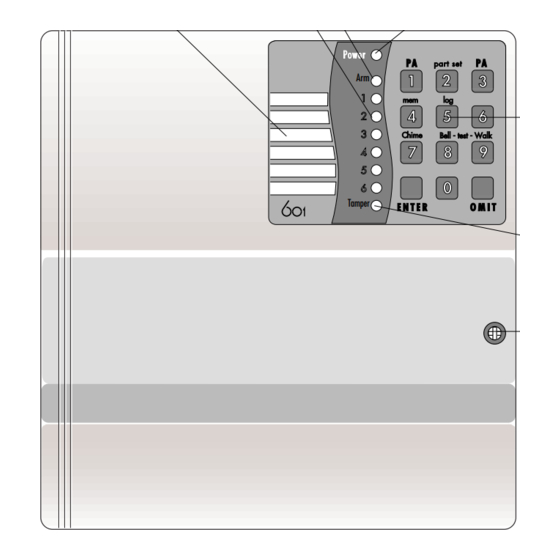
- Page 3 Facilities Alarm Panel. Figure 1 shows the 601 with its controls and displays. Armed LED Write-on Label Power LED Zone LEDs for zone descriptions Illuminated Keypad Tamper Tamper LED Lid screw Figure 1. 601 Displays and Controls Access Codes. The user controls the panel by means of four-digit access codes.
- Page 4 2-Ply Entry Timer. You can program the panel to give a 30 second internal alarm if the user over-runs the programmed entry time. The user must unset the panel before the warning ends, or the panel will give a full alarm. Entry Route.
- Page 5 The options are: never (keypad reset only), once, twice, three times or always. Note: This feature does not rearm the speech communicator output. Remote Keypads. The 601/602 can support up to two 625 remote keypads. The keypads provide the same keys, displays and sounders as the main panel 496219 Issue 1...
- Page 6 (see Figure 2). Note that you can disable the Personal Attack signal from the keypad during programming. Note: The 602 is supplied complete with one 625 remote keypad. Keypad Open Keypad Closed Write zones here Fig 2. 625 Remote Keypad Sounders.
-
Page 7: Technical Specification
EMC Standards: Products are tested to EN 50081-1 and EN 50082-1, and are CE marked accordingly. Log: 15 events. Panel Siren: 601 - Yes (80dB at 1m), 602 - not fitted. Extension Sounder: 1 x 9040 16 Ohm loudspeaker/sounder. Battery: 1.9 (2.1)Ah Lead acid gel type rechargeable. -
Page 8: System Planning
System Planning Installation Precautions Make sure that all windows and doors are secure, and do not need repair, before installing the system. Insecure doors and windows can cause false alarms. Make sure there are no pets or movement (for example flapping cur- tains) which will trigger any movement detectors. -
Page 9: First Floor
DOOR CONTACT (ZONE 1) PASSIVE INFRA RED (ZONE 4) KITCHEN D/ROOM CONTROL PANEL LOUNGE HALL DETECTOR ON ZONE 2 PASSIVE INFRA KEYPAD DOOR CONTACT RED (ZONE 3) (ENTRY/EXIT ZONE 1) Figure 3. Ground Floor Plan First Floor DUMMY BELL FITTED AS HIGH AS POSSIBLE BATHROOM BEDROOM 2... - Page 10 Figure 4 shows a PIR fitted on the landing (zone 5). Anyone entering a room through a window and then entering the landing will cause an alarm when they move onto the landing. A PA button is fitted in bedroom 1, connected to zone 6. During part set zone 5 is inhibited to allow movement in the upper part of the house.
-
Page 11: Installation
Installation Figures 5 and 6 show the layout of the panel inside the case and the connec- tors available. AREA FOR 660 COMMUNICATOR PANEL SPEAKER IN 601 (NOT IN 602) FIXING HOLE AREA FOR 660 COMMUNICATOR IN 602 EUROTYPE MAINS... -
Page 12: Battery Connection
Fitting the Control Panel Choose a location where the user can operate the panel easily. (If fitting a 602 choose a convenient location.) Remove the lid screw and open the lid to the left. Note the slotted cen- tral key hole located near the top of the back. Hold the panel in place and mark the position of the central key hole. - Page 13 mon terminal, as do zones 3 and 4, and zones 5 and 6. Make sure the tamper circuit of each detector is connected in series to the A/T connections on the zone connector. } TO ZONE 1 } TO ZONE 2 } TO ZONE 3 } TO ZONE 4 ZONE 1 A/T...
- Page 14 If you wish to connect more than one detector per zone then use the latch facility so that the user can identify which unit has triggered. The panel uses OP1 programmed as ‘set latch’ to keep the activity LED on the active PIR glowing.
- Page 15 Surface contact Control panel Note: If only one contact is fitted, wire it as last contact. Figure 11. Connecting Door Contacts. Fitting and Wiring Remote Keypads Figure 9 shows the connector inside of the 625 remote keypad. 625 Keypad Circuit Board Sounder Tamper Switch...
- Page 16 Cut the address link in the second keypad to change its address. If fitting an Exit Terminate button connect a Normally Open button to the terminals marked 0V and IP on the keypad. Re-assemble the keypad, ensuring that the tamper switch is closed. Connecting Keyswitches Figure 10 below shows an example connection for a typical keyswitch, for fixed or momentary operation.
- Page 17 Wiring External Sounder Figure 11 shows an example of connections for a typical external sounder (see the manufacturers instructions supplied with individual units for further infor- mation on wiring diagrams) 9040 16Ohm SPEAKER CONTROL PANEL BELL OR SIREN (350 mA) Stb Bell 12V 0V TR LS LS OP1 SIG ARM RDY TYPICAL BELL MODULE BELL...
- Page 18 Fitting a Speech Communicator Note: Disconnect the speech communicator wiring harness from the main pcb if you are NOT fitting a communicator. Figure 12 shows the connector for the speech communicator. Harness Plug Locator Figure 12. Speech Communicator Connections If required the 660 speech/digital communicator can be fitted inside the back casing of the panel.
-
Page 19: Initial Power Up
Note: The panel will not enter programming mode if the global anti tamper is open circuit, or if the negative tamper return is not present. Close the 601 (or 602) lid or defeat the lid tamper. Apply mains power to the 601/602. -
Page 20: Default Settings
(inactive). * The default code for user two is ‘0001’, for user 3 it is ‘0002’ and so on up to user 8, which is ‘0007’. Refer to the 601 User Guide for instructions on changing the user codes. Programming Commands... - Page 21 To change Key in: Followed by: + ENTER Zones 1-6 01-06 0= Not used 1= Normal Alarm 2 = 24 Hour Alarm Example: 3 = Entry Route Select one zone type from 4 = Entry/Exit 0 to 7. 5 = PA Choose which attributes 6 = Fire Alarm you require from 8, 9 and...
- Page 22 To change Key in: Followed by: + ENTER External sounder delay 0 = Nil 1 = 1.5 mins 2 = 3 mins 3 = 5 mins 4 = 10 mins 5 = 15 mins 6 = 20 mins Ext. sounder duration 0 = Nil 1 = 1.5 mins 2 = 3 mins (default)
-
Page 23: To Re-Enter Programming Mode
Note: Leave the lid open and make sure the Lid Tamper switch does not close, or this procedure will not work. On the 601: hold down OMIT and 9 and reconnect battery supply. On the 602: short together the two RST pins on the main pcb with a small screwdriver and reconnect battery supply. - Page 24 Testing Once the panel is installed, connected and programmed, there are several pro- gramming commands that can be used to test it while in Programming Mode. These are listed below (Press ENTER to stop any test.): To Test Key in: Followed by: Engineer Log 4 see earlier events.
-
Page 25: Fault Finding Guide
Fault Finding Guide Symptom Response • POWER LED FLASHES CONTINUOUSLY. • Mains supply has failed, panel operating from battery only. • Check mains connection and fuse. • SAB WILL NOT STOP RINGING. • SAB not receiving power. • Check 12V supply present. •... - Page 26 MANUFACTURED IN THE UK BY SCANTRONIC LTD. PRODUCT SUPPORT (UK) - TEL - (0891) 616343 BETWEEN 09:00 AND 17:30, MONDAY TO FRIDAY. (CALLS CHARGED AT 39P PER MINUTE CHEAP RATE, 49P PER MINUTE AT ANY OTHER TIME.) PRODUCT SUPPORT FAX NO. (01594) 544136.
Need help?
Do you have a question about the 601 and is the answer not in the manual?
Questions and answers