Toro Power Max 1028LXE Operator's Manual
Hide thumbs
Also See for Power Max 1028LXE:
- Operator's manual (26 pages) ,
- Operator's manual (25 pages) ,
- Operator's manual (25 pages)
Table of Contents
Advertisement
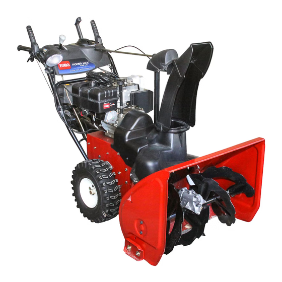
Power Max™ 1028LXE Snowthrower
Model No. 38640—Serial No. 270000001 and Up
Introduction
Read this information carefully to learn how to operate
and maintain your product properly and to avoid injury
and product damage. You are responsible for operating
the product properly and safely.
You may contact Toro directly at www.Toro.com for
product and accessory information, help finding a
dealer, or to register your product.
Whenever you need service, genuine Toro parts,
or additional information, contact an Authorized
Service Dealer or Toro Customer Service and have
the model and serial numbers of your product ready.
Figure 1 identifies the location of the model and serial
numbers on the product. Write the numbers in the
space provided.
Figure 1
1. Model and serial number location
Model No.
Serial No.
This manual identifies potential hazards and has
safety messages identified by the safety alert symbol
(Figure 2), which signals a hazard that may cause serious
injury or death if you do not follow the recommended
precautions.
© 2007—The Toro® Company
8111 Lyndale Avenue South
Bloomington, MN 55420
1. Safety alert symbol
This manual uses 2 words to highlight information.
Important calls attention to special mechanical
information and Note emphasizes general information
worthy of special attention.
The engine exhaust from this product
contains chemicals known to the State of
California to cause cancer, birth defects,
This spark ignition system complies with Canadian
ICES-002.
The enclosed
for information regarding the US Environmental
Protection Agency (EPA) and the California
Emission Control Regulation of emission systems,
maintenance, and warranty. Replacements may be
ordered through the engine manufacturer.
Register at www.Toro.com.
Form No. 3358-623 Rev A
Operator's Manual
Figure 2
Warning
CALIFORNIA
Proposition 65 Warning
or other reproductive harm.
Engine Owner's Manual
Original Instructions (EN)
is supplied
Printed in the USA
All Rights Reserved
Advertisement
Table of Contents

Related Manuals for Toro Power Max 1028LXE


Summary of Contents for Toro Power Max 1028LXE
- Page 1 You are responsible for operating the product properly and safely. This manual uses 2 words to highlight information. You may contact Toro directly at www.Toro.com for Important calls attention to special mechanical product and accessory information, help finding a information and Note emphasizes general information dealer, or to register your product.
-
Page 2: Before Operating
Safety Before Operating Caution: Improper use may result in loss of fingers, hands, or feet. Read and understand the contents of this manual before operating the snowthrower There is a high-speed Become familiar with all controls and know impeller close to the how to stop the engine quickly opening. -
Page 3: Clearing A Clogged Discharge Chute
place containers on the ground, away from your away from the plug to prevent someone from vehicle, before filling. accidentally starting the engine. – When practical, remove gas-powered equipment • Do not run the engine indoors, except when starting from the truck or trailer and refuel it on the the engine and for transporting the snow thrower ground. -
Page 4: Toro Snowthrower Safety
Remove the key from the ignition switch before storing the snowthrower. The following list contains safety information specific • Purchase only genuine Toro replacement parts and to Toro products or other safety information that you accessories. must know. • Rotating auger/impeller can cut off or injure Safety and Instructional fingers or hands. - Page 5 Tecumseh Part No. 35077 1. Key ignition 5. Increasing scale 2. Engage to start the engine 6. Slow 3. Disengage to stop the 7. Stop the engine engine 4. Fast 106-4525 Reorder part no. 112-6632 1. Fast 3. Slow 2. Forward speeds 4.
-
Page 6: Loose Parts
112-6622 1. Left turn control 3. Auger/impeller 5. Read the Operator’s 7. Thrown objects, keep drive—squeeze the lever to Manual. bystanders a safe distance engage; release the lever from the snowthrower. to disengage. 2. Traction drive—squeeze 4. Right turn control 6. -
Page 7: Installing The Upper Handle
1. Installing the Upper Handle 2. Installing the Wheel Clutch Cable Ends Handle bolts Curved washers Procedure Locknuts 1. Unwrap the cable ends from the lower handle (Figure 5). Procedure Note: Do not remove the rubber band on the cables until you have installed the upper handle. -
Page 8: Installing The Traction Control Linkage
Important: Ensure that the curved side of the cable clamp is against the handle and that the cable is routed below the clamp bolt. The cable must be in a straight line from the cable clamp to the point where it attaches to the wheel clutch lever. -
Page 9: Installing Chute Control Rod
6. Lift up on the speed control rod and insert the trunnion into the hole in the speed selector lever (Figure 11). Note: If the trunnion does not fit into the hole when you lift up on the speed control rod, rotate the trunnion upward or downward on the speed control rod until it fits. -
Page 10: Filling The Engine With Oil
6. Filling the Engine with Oil Procedure Your snowthrower comes with 26 oz. of oil in the engine. Note: Before starting the engine, check the oil level and add oil if necessary. Figure 16 Max. fill: 26 oz. (0.77 l), type: automotive detergent 1. -
Page 11: Checking The Skids And Scraper
8. Checking the Skids and C. Turn the trunnion downward (clockwise) on the speed control rod (Figure 11). Scraper D. Connect the trunnion to the speed selector lever (Figure 11). Procedure 4. Release the traction lever. Refer to Checking and Adjusting the Skids and Scraper 5. -
Page 12: Product Overview
Product Overview Figure 22 1. Snow cleanout tool (attached to the handle) Operation Note: Determine the left and right sides of the machine from the normal operating position. Filling the Fuel Tank Gasoline is extremely flammable and explosive. A fire or explosion from gasoline can burn you and others. -
Page 13: Starting The Engine
Figure 26 4. Rotate the choke to the On position (Figure 27). Figure 23 Starting the Engine 1. Connect the spark plug wire (Figure 24). Figure 27 5. Insert the ignition key (Figure 28). Figure 24 Figure 28 2. Move the throttle to the Fast position (Figure 25). 6. -
Page 14: Stopping The Engine
Stopping the Engine Note: Priming excessively may flood the engine and prevent it from starting. 1. Move the throttle to the Stop position (Figure 31). 7. Start the snowthrower using the recoil starter or the electric starter (Figure 30). Figure 31 2. -
Page 15: Operating The Traction Drive
Operating the Traction Drive If the traction drive is not properly adjusted, the snowthrower may move in the direction opposite of what you intended, causing injury and/or property damage. Figure 34 Carefully check the traction drive and adjust it properly, if necessary; refer to Checking the Note: This disengages the drive to the right wheel while Traction Drive Operation in Setup for more the left wheel continues driving, and the snowthrower... -
Page 16: Operating The Speed Selector
Operating the Speed Selector The speed selector has 6 forward and 2 reverse gears. If the auger and impeller continue to rotate To change speeds, release the traction lever and shift the when you release the auger/impeller lever, you speed selector lever to the desired position (Figure 36). could seriously injure yourself or others. -
Page 17: Unclogging The Discharge Chute
Unclogging the Discharge • If the chute does not move, refer to Adjusting the Discharge Chute Latch. Chute • If the chute does not turn as far to the left as it does If the auger/impeller is running but there is no snow to the right, ensure that the cable is routed to the coming out of the discharge chute, the discharge chute inside of the handles. -
Page 18: Operating Tips
Operating Tips When the snowthrower is in operation, the impeller and auger can rotate and cut off or injure hands and feet. • Before adjusting, cleaning, inspecting, troubleshooting, or repairing the snowthrower, stop the engine and wait for all moving parts to stop. Disconnect the wire from the spark plug and keep it away from the plug to prevent someone from accidentally starting the engine. -
Page 19: Recommended Maintenance Schedule(S)
Important: You can find more information about maintaining and servicing your snowthrower at www.Toro.com. Important: Refer to your engine operator’s manual for additional maintenance procedures. For engine adjustments, repairs, or warranty service not covered in this manual, contact an Authorized Tecumseh Servicing Dealer. -
Page 20: Checking And Adjusting The Skids And Scraper
surfaces, adjust the skids further down to prevent the snowthrower from picking up rocks. 5. Move the skids down until they are even with the ground. 6. Firmly tighten the nuts that secure both skids to the auger sides. Note: To quickly adjust the skids if they loosen, support the scraper 1/8 inch (3 mm) off the pavement, then adjust the skids down to the pavement. -
Page 21: Checking And Adjusting The Auger/Impeller Cable
2. Loosen or tighten the turnbuckle to adjust the pin until it is the proper gap from the front edge of the slot. 3. Tighten the jam nut (Figure 45). Figure 47 1. Tab 4. If the auger/impeller cable is not properly adjusted, do the following steps: Figure 45 5. -
Page 22: Checking The Auger Gearbox Oil Level
Checking the Auger Gearbox Oil Level Service Interval: Yearly—Check the auger gearbox oil and add oil if necessary. Figure 50 1. Move the snowthrower to a level surface. 1. Oil drain cap 2. Clean the area around the pipe plug (Figure 49). 2. -
Page 23: Adjusting The Discharge Chute Latch
Note: If you do not have a torque wrench, tighten the plug firmly. Adjusting the Discharge Chute Latch Figure 52 If the discharge chute does not lock into the desired 1. Back cover position or does not unlock so that you can move it to another position, adjust the discharge chute latch. -
Page 24: Replacing The Drive Belts
Replacing the Drive Belts If the auger/impeller drive belt or the traction drive belt becomes worn, oil-soaked, or otherwise damaged, go to www.Toro.com for additional service information or have an Authorized Service Dealer replace the belt. Replacing the Headlight Bulb Figure 60 Use a GE 892 16W halogen light bulb. -
Page 25: Preparing The Snowthrower For Storage
10. Remove the ignition key. 11. Disconnect the spark plug wire. 12. Remove the spark plug, add 1 oz. (30 ml) of oil through the spark plug hole, and pull the starter rope slowly several times to distribute oil throughout the cylinder to prevent cylinder corrosion during the off-season. -
Page 26: Troubleshooting
5. Unclog the discharge chute. 6. The auger/impeller drive belt is loose 6. Install and/or adjust the auger/impeller or is off the pulley. drive belt; refer to www.Toro.com for servicing information or take the snowthrower to an Authorized Service Dealer. - Page 27 Corrective Action 7. The auger/impeller drive belt is worn 7. Replace the auger/impeller drive belt; or broken. refer to www.Toro.com for servicing information or take the snowthrower to an Authorized Service Dealer. Discharge chute either does not lock into 1. The discharge chute latch is not 1.
- Page 28 (Dealer) to obtain guarantee policies for your country, province, or state. If for any reason you are dissatised with your Distributor’s service or have difculty obtaining guarantee information, contact the Toro importer. If all other remedies fail, you may contact us at Toro Warranty Company.