Table of Contents
Advertisement
Quick Links
Power Max® 1028LXE Snowthrower
Model No. 38641—Serial No. 260000001 and Up
Introduction
Read this information carefully to learn how to operate and
maintain your product properly and to avoid injury and
product damage. You are responsible for operating the
product properly and safely.
You may contact Toro directly at www.Toro.com for
product and accessory information, help finding a dealer,
or to register your product.
Whenever you need service, genuine Toro parts, or
additional information, contact an Authorized Service
Dealer or Toro Customer Service and have the model and
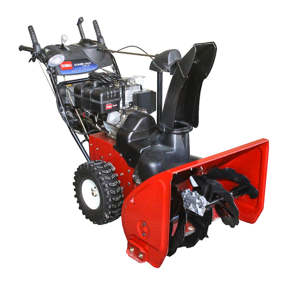
serial numbers of your product ready. Figure 1 identifies the
location of the model and serial numbers on the product.
Write the numbers in the space provided.
Figure 1
1. Model and serial number location
Model No.
Serial No.
This manual identifies potential hazards and has safety
messages identified by the safety alert symbol (Figure 2),
which signals a hazard that may cause serious injury or
death if you do not follow the recommended precautions.
Figure 2
1. Safety alert symbol
© 2005—The Toro® Company
8111 Lyndale Avenue South
Bloomington, MN 55420
This manual uses 2 other words to highlight information.
Important calls attention to special mechanical information
and Note emphasizes general information worthy of special
attention.
Replacement Engine Owner's Manuals may be ordered
through the engine manufacturer.
Register at www.Toro.com.
Form No. 3354-343 Rev B
Operator's Manual
Original Instructions (EN)
Printed in the USA
All Rights Reserved
Advertisement
Table of Contents

Related Manuals for Toro 38641


Summary of Contents for Toro 38641
- Page 1 Whenever you need service, genuine Toro parts, or additional information, contact an Authorized Service Dealer or Toro Customer Service and have the model and serial numbers of your product ready. Figure 1 identifies the location of the model and serial numbers on the product.
- Page 2 Safety Bef or e Ope r a t ing Ca u ti o n : Im p r o p er u se ma y r e su lt in lo ss o f fin g e r , h a n d s, o r fe e t. Re a d a nd unders t a n d t he cont e n t s o f t hi s manual b...
-
Page 3: Maintenance And Storage
Stop the engine whenever you leave the operating position, before unclogging the auger/impeller housing The following list contains safety information specific to or discharge chute, and when making any repairs, Toro products or other safety information that you must adjustments, or inspections. know. •... -
Page 4: Sound Pressure
Remove the key from the ignition switch before storing the snowthrower. This unit does not exceed a hand/arm vibration level of • Purchase only genuine Toro replacement parts and 7.0 m/s , based on measurements of identical machines accessories. per EN 1033. - Page 5 107-3040 1. Cutting dismemberment, impeller and cutting dismemberment, auger hazards—keep bystanders a safe distance from the snowthrower. 106-4525 Reorder part no. 107-3825 1. Warning—hot surface, do not touch 1. Fast 3. Slow 2. Forward speeds 4. Reverse speeds Tecumseh Part No. 36501 1.
-
Page 6: Loose Parts
Setup Loose Parts Use the chart below to verify that all parts have been shipped. Step Qty. Description Handle bolts Curved washers Install the upper handle. Locknuts – No parts required Install the wheel clutch cable ends – No parts required Install the traction control linkage. - Page 7 Figure 7 1. Cable clamp Important: Ensure that the curved side of the cable clamp is against the handle and that the cable is routed below the clamp bolt. The cable must be Figure 4 in a straight line from the cable clamp to the point where it attaches to the wheel clutch lever.
- Page 8 Note: If the trunnion does not fit into the hole when of the rod into the lower link arm so that the bent end of the speed control rod faces rearward (Figure 10). you lift up on the speed control rod, rotate the trunnion upward or downward on the speed control rod until it fits.
-
Page 9: Filling The Engine With Oil
4. Insert the front end of the rod into the opening in the back of the chute gear cover until it slides into the chute gear (Figure 15). Figure 17 1. Plastic clip on wire 3. Cable tie connector 2. U-bolt Figure 15 Note: Ensure that the plastic clip on the wire 5. -
Page 10: Product Overview
Product Overview Figure 18 2. Install the dipstick securely. Note: Do not spill oil around the oil fill tube; oil could leak onto traction parts and cause the traction to slip. 7. Checking the Tire Pressure The tires are overinflated at the factory for shipping. Reduce Figure 19 the pressure equally in both tires to between 17 and 20 psi 1. -
Page 11: Operation
Operation Fill the fuel tank with fresh unleaded regular gasoline from a major name-brand service station (Figure 23). Note: Determine the left and right sides of the machine Important: To reduce starting problems, add fuel from the normal operating position. stabilizer to the fuel all season, mixing it with gasoline less than 30 days old. - Page 12 Figure 29 Note: Take your glove off when you push in the Figure 25 primer so that air cannot escape from the primer hole. 3. Rotate the fuel shutoff valve counterclockwise to open Note: Priming excessively may flood the engine and it (Figure 26).
-
Page 13: Stopping The Engine
If you leave the snowthrower plugged into a power outlet, someone can inadvertently start the snowthrower and injure people or damage property. Unplug the power cord whenever you are not starting the snowthrower. Figure 33 Stopping the Engine 2. To stop the traction drive, release the traction lever. 3. - Page 14 Operating the Auger/Impeller Drive 1. To engage the auger/ impeller drive, squeeze the right hand (auger/ impeller) lever to the handgrip (Figure 37). Figure 34 Note: This disengages the drive to the right wheel while the left wheel continues driving, and the snowthrower turns to the right.
-
Page 15: Preventing Freeze-Up
Figure 38 Moving the Discharge Chute Figure 40 Unclogging the Discharge Hold the blue trigger cap down and move the Quick Stick Chute to the left to move the discharge chute to the left; move the Quick Stick to the right to move the discharge chute to the right (Figure 39). -
Page 16: Operating Tips
Yearly or before storage • Have an Authorized Service Dealer inspect and replace the traction drive belt and/or the auger/impeller drive belt, if necessary. Important: You can find more information about maintaining and servicing your snowthrower at www.Toro.com. -
Page 17: Preparing For Maintenance
Important: Refer to your engine operator’s manual for additional maintenance procedures. For engine adjustments, repairs, or warranty service not covered in this manual, contact an Authorized Tecumseh Servicing Dealer. Preparing for Maintenance 1. Check the tire pressure. Refer to Checking the Tire Pressure. - Page 18 1.5 mm) from the front of the slot to the front edge of the pin (Figure 44). Figure 46 3. With the auger/impeller lever disengaged, ensure that the gap between the auger clutch assembly and the tab Figure 44 is 1/16 inch (1.5 mm) (Figure 47). 1.
-
Page 19: Changing The Engine Oil
7. Adjust the turnbuckle until you obtain the proper gap. 8. Tighten the jam nut. 9. Insert the 2 screws you previously removed on the belt cover. 10. If the auger/impeller cable is properly adjusted but a Figure 50 problem remains, contact an Authorized Service Dealer. 1. -
Page 20: Inspecting And Replacing The Spark Plug
4. Move the speed selector lever to Position R2. 5. Dip your finger in automotive engine oil and lightly lubricate hex shaft. 6. Move the speed selector lever to Position 6. 7. Lubricate the other end of the hex shaft. 8. -
Page 21: Replacing The Drive Belts
Replacing the Drive Belts If the auger/impeller drive belt or the traction drive belt becomes worn, oil-soaked, or otherwise damaged, go to www.Toro.com for additional service information or have an Authorized Service Dealer replace the belt. Replacing the Headlight Bulb Figure 60 5. - Page 22 Storage 2. Install the spark plug by hand and then torque it to 15 ft-lb (20.4 N·m). 3. Connect the spark plug wire. 4. Perform the annual maintenance procedures as given in • Gasoline vapors can explode. the Recommended Maintenance Schedule. •...
-
Page 23: Troubleshooting
Troubleshooting Problem Possible Cause Corrective Action Electric starter does not turn 1. The power cord is 1. Connect the power cord (electric-start models only) disconnected at the outlet or to the outlet and/or the the snowthrower. snowthrower. 2. The power cord is worn, 2. - Page 24 6. The auger/impeller drive belt 6. Install and/or adjust the is loose or is off the pulley. auger/impeller drive belt; refer to www.Toro.com for servicing information or take the snowthrower to an Authorized Service Dealer. 7. The auger/impeller drive belt 7.