Table of Contents
Advertisement
Advertisement
Table of Contents
Troubleshooting

Related Manuals for Mitsubishi Electric CMB-WP1016V-GA1


Summary of Contents for Mitsubishi Electric CMB-WP1016V-GA1
-
Page 2: Safety Precautions
Do not touch the heat exchanger fins. It may also be in violation of applicable laws. The fins are sharp and dangerous. MITSUBISHI ELECTRIC CORPORATION cannot be held responsible for malfunctions or accidents resulting from the In the event of a refrigerant leak, thoroughly ventilate use of the wrong type of refrigerant. - Page 3 WARNING Securely attach the terminal block cover (panel) to the After completing the service work, check for a gas unit. leak. If the terminal block cover (panel) is not installed properly, If leaked refrigerant is exposed to a heat source, such as a dust and/or water may infiltrate and pose a risk of electric fan heater, stove, or electric grill, poisonous gases may be shock, smoke, and/or fire.
- Page 4 Precautions for handling units for use with R410A CAUTION Do not use the existing refrigerant piping. Use a vacuum pump with a reverse-flow check valve. A large amount of chlorine that may be contained in the re- If a vacuum pump that is not equipped with a reverse-flow sidual refrigerant and refrigerating machine oil in the exist- check valve is used, the vacuum pump oil may flow into the ing piping may cause the refrigerating machine oil in the...
-
Page 5: Before Installing The Unit
Before installing the unit WARNING Do not install the unit where a gas leak may occur. When installing the unit in a hospital, take appropriate measures to reduce noise interference. If gaseous refrigerant leaks and piles up around the unit, it may be ignited. -
Page 6: Electrical Work
Before installing the unit (moving and reinstalling the unit) and performing electrical work CAUTION Properly ground the unit. Periodically check the installation base for damage. Do not connect the grounding wire to a gas pipe, water pipe, If the unit is left on a damaged platform, it may fall and lightning rod, or grounding wire from a telephone pole. - Page 7 Before the test run CAUTION Turn on the unit at least 12 hours before the test run. Do not turn off the power immediately after stopping the operation. Keep the unit turned on throughout the season. If the unit is turned off in the middle of a season, it may result in malfunc- Keep the unit on for at least five minutes before turning off tions.
-
Page 8: Table Of Contents
CONTENTS I Read Before Servicing [1] Read Before Servicing......................3 [2] Necessary Tools and Materials ....................4 [3] Piping Materials ........................5 [4] Storage of Piping ........................7 [5] Pipe Processing........................7 [6] Brazing............................8 [7] Air Tightness Test (Refrigerant Circuit) ..................9 [8] Vacuum Drying (Evacuation) (Refrigerant Circuit).............. - Page 9 HWE1410A...
- Page 10 I Read Before Servicing [1] Read Before Servicing ....................... 3 [2] Necessary Tools and Materials..................4 [3] Piping Materials ......................... 5 [4] Storage of Piping ....................... 7 [5] Pipe Processing ......................... 7 [6] Brazing..........................8 [7] Air Tightness Test (Refrigerant Circuit)................9 [8] Vacuum Drying (Evacuation) (Refrigerant Circuit)............
- Page 11 - 2 - HWE1410A...
-
Page 12: Read Before Servicing
[ I Read Before Servicing ] I Read Before Servicing [1] Read Before Servicing 1. Check the type of refrigerant used in the system to be serviced. Refrigerant Type Multi air conditioner for building application CITY MULTI R2 YLM series: R410A 2. -
Page 13: Necessary Tools And Materials
[ I Read Before Servicing ] [2] Necessary Tools and Materials Prepare the following tools and materials necessary for installing and servicing the unit. Tools for use with R410A (Adaptability of tools that are for use with R22 or R407C) 1. -
Page 14: Piping Materials
[ I Read Before Servicing ] [3] Piping Materials Do not use the existing piping! 1. Copper pipe materials O-material (Soft Annealed) Soft copper pipes (annealed copper pipes). They can easily be bent with hands. 1/2H-material (Light Annealed) Hard copper pipes (straight pipes). They are stronger than the O-material (Soft An- nealed) at the same radial thickness. - Page 15 [ I Read Before Servicing ] 4. Thickness and refrigerant type indicated on the piping materials Ask the pipe manufacturer for the symbols indicated on the piping material for new refrigerant. 5. Flare processing (O-material (Soft Annealed) and OL-material only) The flare processing dimensions for the pipes that are used in the R410A system are larger than those in the R22 system.
-
Page 16: Storage Of Piping
[ I Read Before Servicing ] [4] Storage of Piping 1. Storage location Store the pipes to be used indoors. (Warehouse at site or owner's warehouse) If they are left outdoors, dust, dirt, or moisture may infiltrate and contaminate the pipe. 2. -
Page 17: Brazing
[ I Read Before Servicing ] [6] Brazing No changes have been made in the brazing procedures. Perform brazing with special care to keep foreign objects (such as oxide scale, water, and dust) out of the refrigerant system. Example: Inside the brazed connection Use of oxidized solder for brazing Use of non-oxidized solder for brazing 1. -
Page 18: Air Tightness Test (Refrigerant Circuit)
[ I Read Before Servicing ] [7] Air Tightness Test (Refrigerant Circuit) No changes have been made in the detection method. Note that a refrigerant leak detector for R22 will not detect an R410A leak. Halide torch R22 leakage detector 1. -
Page 19: Vacuum Drying (Evacuation) (Refrigerant Circuit)
[ I Read Before Servicing ] [8] Vacuum Drying (Evacuation) (Refrigerant Circuit) (Photo1) 15010H (Photo2) 14010 Recommended vacuum gauge: ROBINAIR 14010 Thermistor Vacuum Gauge 1. Vacuum pump with a reverse-flow check valve (Photo1) To prevent the vacuum pump oil from flowing into the refrigerant circuit during power OFF or power failure, use a vacuum pump with a reverse-flow check valve. - Page 20 [ I Read Before Servicing ] 7. Notes To evacuate air from the entire system Applying a vacuum through the check joints at the refrigerant service valve on the high and low pressure sides (BV1 and 2) is not enough to attain the desired vacuum pressure. Be sure to apply a vacuum through the check joints at the refrigerant service valve on the high and low pressure sides (BV1 and 2) and also through the check joints on the high and low pressure sides (CJ1 and 2).
-
Page 21: Refrigerant Charging
[ I Read Before Servicing ] [9] Refrigerant Charging Cylinder with a siphon Cylinder without a siphon Cylin- Cylin- Cylinder color R410A is pink. Refrigerant charging in the liquid state Valve Valve liquid liquid 1. Reasons R410A is a pseudo-azeotropic HFC blend (boiling point R32=-52°C[-62°F], R125=-49°C[-52°F]) and can almost be handled the same way as a single refrigerant, such as R22. -
Page 22: Characteristics Of The Conventional And The New Refrigerants
[ I Read Before Servicing ] [11] Characteristics of the Conventional and the New Refrigerants 1. Chemical property As with R22, the new refrigerant (R410A) is low in toxicity and chemically stable nonflammable refrigerant. However, because the specific gravity of vapor refrigerant is greater than that of air, leaked refrigerant in a closed room will accumulate at the bottom of the room and may cause hypoxia. -
Page 23: Notes On Refrigerating Machine Oil
[ I Read Before Servicing ] [12] Notes on Refrigerating Machine Oil 1. Refrigerating machine oil in the HFC refrigerant system HFC type refrigerants use a refrigerating machine oil different from that used in the R22 system. Note that the ester oil used in the system has properties that are different from commercially available ester oil. Refrigerant Refrigerating machine oil Mineral oil... -
Page 24: Water Piping
[ I Read Before Servicing ] [13] Water piping 1. Precautions for water piping Consider the following when installing a water piping system. (1) Design pressure of the water piping Use a water pipe that can withstand pressure of at least 1.0 MPa. (2) Water pipe type Use of plastic pipe is recommended.Do not use chloride plastic pipes. - Page 25 [ I Read Before Servicing ] 2. Notes on corrosion (1) Water quality It is important to check the water quality beforehand. See table below (Circulating water/Makeup Water Quality Standards). Lower mid-range Tendency temperature water system Recirculating Items water Make-up Scale- Corrosive [20<T<60°C]...
- Page 26 [ I Read Before Servicing ] 3. Correction by antifreeze-liquid concentration In HYBRID CITY MULTI system, antifreeze-liquid should be used to prevent the system from freezing. Refer to the following graphs for the capacity correction by antifreeze-liquid. Refer to (1) for antifreeze-liquid concentration, (2) and (3) for capacity correction by antifreeze-liquid concentration.
- Page 27 [ I Read Before Servicing ] - 18 - HWE1410A...
-
Page 28: Ii Restrictions
II Restrictions [1] System configuration ....................... 21 [2] Switch Settings and Address Settings ................22 [3] An Example of a System to which an MA Remote Controller is connected..... 24 [4] An Example of a System to which an ME Remote Controller is connected..... 30 [5] An Example of a System to which both MA Remote Controller and ME Remote Controller are connected................ - Page 29 - 20 - HWE1410A...
-
Page 30: System Configuration
Sub-HBC of connectable indoor of connectable in- indoor units units door units (E)P200 CMB-WP108V-GA1, 100 - 300 WP15- WP50 models CMB-WP1016V-GA1 Indoor units for use with (E)P250 125 - 375 HBC controller CMB-WP108V-GB1, (E)P300 150 - 450 CMB-WP1016V-GB1 (E)P350 175 - 525... -
Page 31: Switch Settings And Address Settings
[ II Restrictions ] [2] Switch Settings and Address Settings 1. Switch setting Refer to section "[3] An Example of a System to which an MA Remote Controller is connected - [5] An Example of a System to which both MA Remote Controller and ME Remote Controller are connected" before performing wiring work. Set the switches while the power is turned off. - Page 32 [ II Restrictions ] 2. M-NET Address settings (1) Address settings table The need for address settings and the range of address setting depend on the configuration of the system. Unit or controller Sym- Address Setting method Factory setting address range setting CITY MULTI...
-
Page 33: An Example Of A System To Which An Ma Remote Controller Is Connected
[ II Restrictions ] [3] An Example of a System to which an MA Remote Controller is connected 1. System with one outdoor unit (Heat source unit) (automatic address setup for both indoor and outdoor units) (1) Sample control wiring Interlock operation with the ventilation unit Leave the male... - Page 34 [ II Restrictions ] 3) MA remote controller wiring (4) Wiring method Connect terminals 1 and 2 on the terminal block for MA 1) Indoor/outdoor transmission line remote controller line (TB15) on the indoor unit (IC) to the Daisy-chain terminals M1 and M2 of the terminal block terminal block on the MA remote controller (MA).
- Page 35 [ II Restrictions ] 2. A system in which a system controller is connected to the transmission line for centralized control and which is pow- ered from an outdoor unit (1) Sample control wiring Interlock operation with the ventilation unit Move the male connector Leave the male from CN41 to CN40.
- Page 36 [ II Restrictions ] (4) Wiring method a) The outdoor units in the same refrigerant circuit are automatical- 1) Indoor/outdoor transmission line ly designated as OC and OS in the order of capacity from large Daisy-chain terminals M1 and M2 of the terminal block to small (if two or more units have the same capacity, in the or- for indoor-outdoor transmission line (TB3) on the outdoor der of address from small to large).
- Page 37 [ II Restrictions ] 3. An example of a system in which a system controller is connected to the indoor-outdoor transmission line (except LM adapter) (1) Sample control wiring Interlock operation with the ventilation unit CN41 CN40 Replace Leave the male SW2-1 OFF ON connector on CN41 as it is.
- Page 38 [ II Restrictions ] (4) Wiring method b) If TB7's on the outdoor units in the same refrigerant circuit are not 1) Indoor/outdoor transmission line daisy-chained, connect the transmission line for the central control system to TB7 of the OC. (Note a).To maintain the central control Daisy-chain terminals M1 and M2 of the terminal block for indoor- even during an OC failure or a power failure, connect TB7 on OC outdoor transmission line (TB3) on the outdoor units (OC and OS)
-
Page 39: An Example Of A System To Which An Me Remote Controller Is Connected
[ II Restrictions ] [4] An Example of a System to which an ME Remote Controller is connected (1) Sample control wiring Interlock operation with the ventilation unit Move the male connector Leave the male from CN41 to CN40. connector on SW2-1 OFF ON CN41 as it is. - Page 40 [ II Restrictions ] door-outdoor transmission line. (4) Wiring method When 2 remote controllers are connected to the sys- 1) Indoor/outdoor transmission line Same as [3] 2. Refer to the section on Switch Setting. Shielded cable connection Performing a group operation (including the group Same as [3] 2.
-
Page 41: An Example Of A System To Which Both Ma Remote Controller And Me Remote Controller Are Connected
[ II Restrictions ] [5] An Example of a System to which both MA Remote Controller and ME Remote Controller are connected (1) Sample control wiring Move the male connector Leave the male from CN41 to CN40. Group Group connector on SW2-1 OFF ON CN41 as it is. - Page 42 [ II Restrictions ] (3) Maximum allowable length (4) Wiring method 1) Indoor/outdoor transmission line 1) Indoor/outdoor transmission line Same as [3] 2. Same as [3] 2. 2) Transmission line for centralized control Shielded cable connection Same as [3] 2. Same as [3] 2.
- Page 43 [ II Restrictions ] (5) Address setting method Pro- dress Facto- Unit or controller set- Setting method Notes ry set- dure ting ting range Opera- Main 01 to Assign the smallest address to Assign an address smaller than that of the main unit in the group.
-
Page 44: Restrictions On Pipe Length
[ II Restrictions ] [6] Restrictions on Pipe Length CMB-WP108V-GA1 + CMB-WP108V-GB1 (CMB-WP1016V-GA1) (CMB-WP1016V-GB1) Note:1. Indoor units that are connected to the same branch joint cannot be si- multaneously operated in different operation modes. (Unit: m) Item Piping portion Allowable value... - Page 45 Low pressure side (E)P200 ø15.88 (Brazing) ø19.05 (Brazing) (HBC CONTROLLER) CMB-WP108V-GA1 ø19.05 (Brazing) ø22.2 (Brazing) CMB-WP1016V-GA1 ø19.05 (Brazing) ø22.2 (Brazing) ø19.05 (Brazing) ø28.58 (Brazing) Use of two HBC controllers HBC CONTROLLER Between outdoor unit and twining pipe Between twining pipe and HBC...
-
Page 46: Iii Hbc Controller Components
III HBC Controller Components [1] HBC Controller Components ................... 39 [2] Sub-HBC Components ....................42 [3] Control Box of the HBC Controller and Sub-HBC............44 [4] HBC Controller and Sub-HBC Circuit Board..............45 - 37 - HWE1410A... - Page 47 - 38 - HWE1410A...
-
Page 48: Hbc Controller Components
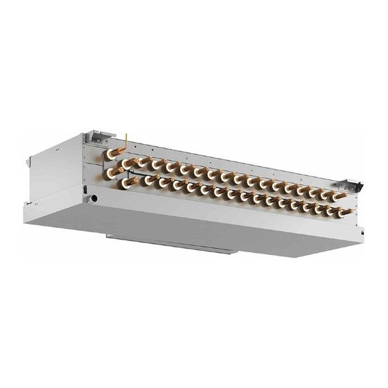
[ III HBC Controller Components ] III HBC Controller Components [1] HBC Controller Components 1. Front (1) CMB-WP1016V-GA1 To Sub-HBC (Hot water) High pressure pipe From Main HBC From Sub-HBC (Hot water) Low pressure pipe Drain From Sub-HBC (Cold water) - Page 49 [ III HBC Controller Components ] 2. Rear right side (cooling) Cooling plate heat exchnger LEV2 21S4Ma Strainer 21S4Mb Pump 2 Water purge valve SVM1 Air purge valve LEV1 LEV3 3. Rear left side (heating) Heating plate heat exchnger Water pressure protection valve Air purge valve Pump1...
- Page 50 [ III HBC Controller Components ] 4. Top side (1) CMB-WP1016V-GA1 VB3f (2) CMB-WP108V-GA1 VB3e - 41 - HWE1410A...
-
Page 51: Sub-Hbc Components
[ III HBC Controller Components ] [2] Sub-HBC Components 1. Front (1) CMB-WP1016V-GB1 To Main_HBC (Hot water) From Main_HBC (Hot water) To Main_HBC (Cold water) From Main_HBC (Cold water) (2) CMB-WP108V-GB1 To Main_HBC (Hot water) From Main_HBC (Hot water) To Main_HBC (Cold water) From Main_HBC (Cold water) - 42 - HWE1410A... - Page 52 [ III HBC Controller Components ] 2. Top side (1) CMB-WP1016V-GB1 VB3f (2) CMB-WP108V-GB1 VB3e - 43 - HWE1410A...
-
Page 53: Control Box Of The Hbc Controller And Sub-Hbc
[ III HBC Controller Components ] [3] Control Box of the HBC Controller and Sub-HBC 1. CMB-WP108V, WP1016V-GA1, CMB-WP108, WP1016V-GB1 Terminal block for transmission line Terminal block for power supply AC reactor (ACL) Power supply circuit board HBC controller board - 44 - HWE1410A... -
Page 54: Hbc Controller And Sub-Hbc Circuit Board
[ III HBC Controller Components ] [4] HBC Controller and Sub-HBC Circuit Board 1. HBC controller and Sub-HBC circuit board - 45 - HWE1410A... - Page 55 [ III HBC Controller Components ] 2. Power supply circuit board - 46 - HWE1410A...
-
Page 56: Iv Electrical Wiring Diagram
IV Electrical Wiring Diagram [1] Electrical Wiring Diagram of the HBC Controller and Sub-HBC ........49 [2] Electrical Wiring Diagram of Transmission Booster............57 - 47 - HWE1410A... - Page 57 - 48 - HWE1410A...
-
Page 58: Electrical Wiring Diagram Of The Hbc Controller And Sub-Hbc
[ IV Electrical Wiring Diagram ] IV Electrical Wiring Diagram [1] Electrical Wiring Diagram of the HBC Controller and Sub-HBC (1) CMB-WP108V-GA1 - 49 - HWE1410A... - Page 59 [ IV Electrical Wiring Diagram ] (2) CMB-WP108V-GA1 (Detail of X section) - 50 - HWE1410A...
- Page 60 [ IV Electrical Wiring Diagram ] (3) CMB-WP1016V-GA1 - 51 - HWE1410A...
- Page 61 [ IV Electrical Wiring Diagram ] (4) CMB-WP1016V-GA1 (Detail of X section) - 52 - HWE1410A...
- Page 62 [ IV Electrical Wiring Diagram ] (5) CMB-WP108V-GB1 - 53 - HWE1410A...
- Page 63 [ IV Electrical Wiring Diagram ] (6) CMB-WP108V-GB1 (Detail of X section) - 54 - HWE1410A...
- Page 64 [ IV Electrical Wiring Diagram ] (7) CMB-WP1016V-GB1 - 55 - HWE1410A...
- Page 65 [ IV Electrical Wiring Diagram ] (8) CMB-WP1016V-GB1 (Detail of X section) - 56 - HWE1410A...
-
Page 66: Electrical Wiring Diagram Of Transmission Booster
[ IV Electrical Wiring Diagram ] [2] Electrical Wiring Diagram of Transmission Booster Terminal block for power supply (TB1) 250V 5A Red Red Red Black White White Green/Yellow 220 - 240VAC Varistor Noise filter Black White White White White Varistor Green Black Stabilized power supply... - Page 67 [ IV Electrical Wiring Diagram ] - 58 - HWE1410A...
-
Page 68: V Refrigerant Circuit
V Refrigerant Circuit [1] Refrigerant Circuit Diagram ..................... 61 [2] Principal Parts and Functions ..................64 - 59 - HWE1410A... - Page 69 - 60 - HWE1410A...
-
Page 70: Refrigerant Circuit Diagram
[ V Refrigerant Circuit ] V Refrigerant Circuit [1] Refrigerant Circuit Diagram 1. HBC controller (1) CMB-WP108V-GA1 - 61 - HWE1410A... - Page 71 [ V Refrigerant Circuit ] (2) CMB-WP1016V-GA1 - 62 - HWE1410A...
- Page 72 [ V Refrigerant Circuit ] 2. Sub-HBC (1) CMB-WP108V-GB1 Sub-HBC water system Air purge valves VB1a T41a TH43 VB1b TH42 No.1 No.4 Port T41b VB1d purge T41d valves VB1e T41e VB1f No.5 No.8 Port T41f VB1h T41h To HBC (2) CMB-WP1016V-GB1 Sub-HBC water system Air purge valves...
-
Page 73: Principal Parts And Functions
[ V Refrigerant Circuit ] [2] Principal Parts and Functions 1. HBC controller Part name Symbols Notes Usage Specifications Check method Solenoid SVM1 Refriger- Opens during the cooling mode AC220-240V Continuity check valve ant side and defrost cycle Open when energized/ with a tester closed when de-energized 4-way... - Page 74 [ V Refrigerant Circuit ] 2. Sub-HBC Part name Symbols Notes Usage Specifications Check method Thermistor TH31a~p Water Indoor unit circulating water con- Same as the table above TH32, 33 side trol Valve VB3a~p Water 1) Switches the water flow DC12V block side...
- Page 75 [ V Refrigerant Circuit ] - 66 - HWE1410A...
-
Page 76: Vi Control
VI Control [1] Functions and Factory Settings of the Dipswitches ............69 [2] Controlling HBC Controller....................70 [3] Operation Flow Chart....................... 79 - 67 - HWE1410A... - Page 77 - 68 - HWE1410A...
-
Page 78: Functions And Factory Settings Of The Dipswitches
[ VI Control ] VI Control [1] Functions and Factory Settings of the Dipswitches 1. Switch functions <HBC controller> (Control board) Function according to switch setting Switch setting tim- Switch Function Always leave this 1 - 3 Model setting R410A switch to OFF. -
Page 79: Controlling Hbc Controller
[ VI Control ] [2] Controlling HBC Controller Water pump control -1- Water pump control Depending on the capacity required, temperature difference on the indoor units is controlled so as to be within a certain range. During normal operation, the changes in specified voltage of the water pump corresponding to the capacity of connectable indoor units are shown in the graph below. - Page 80 [ VI Control ] 4-way valve control -2- 4-way valve control 4-way valves (21S4M (a, b)) turn on or off according to the operation mode. For 21S4Ma, ON indicates switching to the cooling side and OFF indicates switching to the heating side. For 21S4Mb, ON indicates switching to the heating side and OFF indicates switching to the cooling side.
- Page 81 [ VI Control ] Water rate valve control -3- Valve block (VB3) water flow rate adjustment Depending on the capacity required, periodic control is performed every one minute to keep the temperature difference be- tween the heat exchanger outlet pipe temperature and indoor unit port pipe temperature within 4.0ºC for cooling and 4.5ºC for heating, and the opening is controlled in the range between 85 and 700 (cooling) or 900 and 1600 (Heating) pulses.
- Page 82 [ VI Control ] Bypass Control -5- Bypass Control Solenoid valves have two types: (SVM1) that bypass the high- and low- pressure sides; LEV (LEV3). They perform the fol- lowing functions. (1) Bypass solenoid valve (SVM1) (ON: open) SVM1 Operation mode Cooling-only Thermo-ON Always ON Cooling-main Thermo-ON...
-
Page 83: Defrost Operation Control
[ VI Control ] Defrost Operation Control -7- Defrost Operation Control (1) Defrost cycle type The defrost cycle has following two types: Bypass defrost that is the same method as that used in a CITY MULTI series sys- tem and heat recovery defrost (default) that the heat is collected from the water circuit and the defrost cycle ends early. The following figure shows the refrigerant flow for the bypass defrost. - Page 84 [ VI Control ] (3) Defrost cycle Bypass defrost Heat recovery defrost Outdoor Unit Dip switch setting SW3-10 ON SW3-10 OFF Operation mode Heating-only Heating-main Heating-only Heating-main Outdoor unit fre- 103Hz quency Outdoor unit fan Stop SV1a ON (open) SV5b ON (open) 21S4a, 21S4b OFF (closed)
- Page 85 [ VI Control ] (4) Recovering from Defrost The setting of the dip switch 3-10 determines the defrost method (bypass defrost or heat recovery defrost). As shown in the following flow chart, the bypass defrost may be performed during the heat recovery defrost depending on the operation status.
- Page 86 [ VI Control ] Refrigerant Recovery Control -8- Refrigerant Recovery Control The refrigerant recovery control function controls the refrigerant flow at the HBC controller during heating operation to keep the refrigerant from collecting inside the HBC controller. It is also performed during cooling operation to prevent an excessive amount of refrigerant from accumulating in the outdoor heat exchanger.
- Page 87 [ VI Control ] Backup control -9- Backup control The following backup control is started on the HBC as necessary. (1) Backup mode for plate heat exchanger protection The following control is performed depending on the outlet pipe temperature of the plate heat exchanger for freeze-up pro- tection.
-
Page 88: Operation Flow Chart
[ VI Control ] [3] Operation Flow Chart 1. Mode determination flowchart (1) Indoor unit (cooling, heating, dry, fan mode) Start Normal operation Error Breaker Stop turned on Operation SW turned on *Note 1 1. Protection function self-holding cancelled. 2. HBC controller VB3 fully closed. *Note 2 Remote controller Error mode... - Page 89 [ VI Control ] (2) Outdoor unit (cooling only, heating only, cooling main and heating main modes) (Heat source unit) Start Normal operation Error Breaker turned on Unit in the stopped state "HO" / "PLEASE WAIT" blinks *Note 1 on the remote controller Indoor units registered to the remote controller...
- Page 90 [ VI Control ] (3) HBC controller (cooling only, heating only, cooling main and heating main modes) Start Normal operation Error Breaker turned on Unit in the stopped state Operation command 1. Determination of operation mode Protection function (Cooling only, Heating only, Mixture self-holding cancelled.
- Page 91 [ VI Control ] 2. Operations in each mode (1) Cooling operation Cooling operation Normal operation During test run mode 4-way valve OFF Unit in the stopped state Indoor unit fan *Note 1 operation Test run mode Thermostat 3-minute restart prevention 1.
- Page 92 [ VI Control ] (2) Heating operation Normal operation Heating operation Defrost operation *Note 1,2 Unit in the stopped state Defrost operation During test run mode 4-way valve ON 4-way valve OFF Test run mode 1. Indoor unit fan stop 2.
- Page 93 [ VI Control ] (3) Dry operation Dry operation Normal operation Thermostat ON 4-way valve OFF Unit in the stopped state Test run mode *Note 2 Thermostat ON Suction temperature 18 C[64 F] *Note 1 1. Indoor unit fan stop 1.
-
Page 94: Vii Test Run Mode
VII Test Run Mode [1] Items to be checked before a Test Run ................87 [2] Operating Characteristic and Refrigerant Amount ............88 [3] Adjusting the Refrigerant Amount ..................88 [4] Refrigerant Amount Adjust Mode..................91 [5] The following symptoms are normal................91 [6] Standard Operation Data (Reference Data) .............. - Page 95 - 86 - HWE1410A...
-
Page 96: Items To Be Checked Before A Test Run
[ VII Test Run Mode ] VII Test Run Mode [1] Items to be checked before a Test Run (1) Check for refrigerant leak and loose cables and connectors. (2) Measure the insulation resistance between the power supply terminal block and the ground with a 500V megger and make sure it reads at least 1.0Mohm. -
Page 97: Operating Characteristic And Refrigerant Amount
[ VII Test Run Mode ] [2] Operating Characteristic and Refrigerant Amount It is important to have a clear understanding of the characteristics of refrigerant and the operating characteristics of air conditioners before attempting to adjust the refrigerant amount in a given system. 1. - Page 98 [ VII Test Run Mode ] 3. Amount of refrigerant to be added The amount of refrigerant that is shown in the table below is factory-charged to the outdoor units. The amount necessary for extended pipe (field piping) is not included and must be added on site. Outdoor unit model Amount of pre-charged refrigerant Outdoor unit model Amount of pre-charged refrigerant in the outdoor unit (kg)
- Page 99 [ VII Test Run Mode ] Outdoor unit index Diameter of high-pressure pipe (Heat source unit model) (E)P200 ø15.88 (E)P250 ø19.05 (E)P300 ø19.05 (E)P350 ø19.05 (E)P400 ø15.88 (E)P450 ø19.05 (E)P500 ø19.05 Amount for the HBC controller α (kg) Round up the calculation result to the nearest 0.1kg. (Example: 18.04kg to 18.1kg) (2) Example (3) Sample calculation Outdoor unit...
-
Page 100: Refrigerant Amount Adjust Mode
[ VII Test Run Mode ] [4] Refrigerant Amount Adjust Mode On the model of unit described in this document, the refrigerant charge cannot be adjusted. [5] The following symptoms are normal. Remote controller Symptoms Cause display The auto vane adjusts its posi- After an hour of cooling operation with the auto vane in the vertical posi- tion by itself. -
Page 101: Standard Operation Data (Reference Data)
[ VII Test Run Mode ] [6] Standard Operation Data (Reference Data) (1) Cooling only operation Outdoor unit model Operation PURY-P200YLM-A1 PURY-P250YLM-A1 Model name of HBC controller CMB-WP108V-GA1 No. of HBC controllers required 27°C/ 19°C 27°C/ 19°C Indoor [81°F/ 66°F] [81°F/ 66°F] Ambient tem- DB/WB... - Page 102 [ VII Test Run Mode ] Outdoor unit model Operation PURY-P300YLM-A1 PURY-P350YLM-A1 Model name of HBC controller CMB-WP108V-GA1 No. of HBC controllers required 27°C/ 19°C 27°C/ 19°C Indoor [81°F/ 66°F] [81°F/ 66°F] Ambient DB/WB temperature 35°C/ - 35°C/ - Outdoor [95°F/ -] [95°F/ -] No.
- Page 103 [ VII Test Run Mode ] Outdoor unit model Operation PURY-P400YLM-A1 PURY-P450YLM-A1 Model name of HBC controller CMB-WP108V-GA1 No. of HBC controllers required 27°C/ 19°C 27°C/ 19°C Indoor [81°F/ 66°F] [81°F/ 66°F] Ambient tem- DB/WB perature 35°C/ - 35°C/ - Outdoor [95°F/ -] [95°F/ -]...
- Page 104 [ VII Test Run Mode ] Outdoor unit model Operation PURY-P500YLM-A1 Model name of HBC controller CMB-WP108V-GA1 No. of HBC controllers required 27°C/ 19°C Indoor [81°F/ 66°F] Ambient tem- DB/WB perature 35°C/ - Outdoor [95°F/ -] No. of connected units Unit No.
- Page 105 [ VII Test Run Mode ] Outdoor unit model Operation PURY-EP200YLM-A1 PURY-EP250YLM-A1 Model name of HBC controller CMB-WP108V-GA1 No. of HBC controllers required 27°C/ 19°C 27°C/ 19°C Indoor [81°F/ 66°F] [81°F/ 66°F] Ambient tem- DB/WB perature 35°C/ - 35°C/ - Outdoor [95°F/ -] [95°F/ -]...
- Page 106 [ VII Test Run Mode ] Outdoor unit model Operation PURY-EP300YLM-A1 PURY-EP350YLM-A1 Model name of HBC controller CMB-WP108V-GA1 No. of HBC controllers required 27°C/ 19°C 27°C/ 19°C Indoor [81°F/ 66°F] [81°F/ 66°F] Ambient tem- DB/WB perature 35°C/ - 35°C/ - Outdoor [95°F/ -] [95°F/ -]...
- Page 107 [ VII Test Run Mode ] Outdoor unit model Operation PURY-EP400YLM-A1 PURY-EP450YLM-A1 Model name of HBC controller CMB-WP108V-GA1 No. of HBC controllers required 27°C/ 19°C 27°C/ 19°C Indoor [81°F/ 66°F] [81°F/ 66°F] Ambient tem- DB/WB perature 35°C/ - 35°C/ - Outdoor [95°F/ -] [95°F/ -]...
- Page 108 [ VII Test Run Mode ] Outdoor unit model Operation PURY-EP500YLM-A1 Model name of HBC controller CMB-WP108V-GA1 No. of HBC controllers required 27°C/ 19°C Indoor [81°F/ 66°F] Ambient tem- DB/WB perature 35°C/ - Outdoor [95°F/ -] No. of connected units Unit No.
- Page 109 [ VII Test Run Mode ] (2) Heating only operation Outdoor unit model Operation PURY-P200YLM-A1 PURY-P250YLM-A1 Model name of HBC controller CMB-WP108V-GA1 No. of HBC controllers required 20°C/ - 20°C/ - Indoor [68°F/ -] [68°F/ -] Ambient tem- DB/WB perature 7°C/ 6°C 7°C/ 6°C Outdoor...
- Page 110 [ VII Test Run Mode ] Outdoor unit model Operation PURY-P300YLM-A1 PURY-P350YLM-A1 Model name of HBC controller CMB-WP108V-GA1 No. of HBC controllers required 20°C/ - 20°C/ - Indoor [68°F/ -] [68°F/ -] Ambient tem- DB/WB perature 7°C/ 6°C 7°C/ 6°C Outdoor [45°F/ 43°F] [45°F/ 43°F]...
- Page 111 [ VII Test Run Mode ] Outdoor unit model Operation PURY-P400YLM-A1 PURY-P450YLM-A1 Model name of HBC controller CMB-WP108V-GA1 No. of HBC controllers required 20°C/ - 20°C/ - Indoor [68°F/ -] [68°F/ -] Ambient tem- DB/WB perature 7°C/ 6°C 7°C/ 6°C Outdoor [45°F/ 43°F] [45°F/ 43°F]...
- Page 112 [ VII Test Run Mode ] Outdoor unit model Operation PURY-P500YLM-A1 Model name of HBC controller CMB-WP108V-GA1 No. of HBC controllers required 20°C/ - Indoor [68°F/ -] Ambient tem- DB/WB perature 7°C/ 6°C Outdoor [45°F/ 43°F] No. of connected units Unit No.
- Page 113 [ VII Test Run Mode ] Outdoor unit model Operation PURY-EP200YLM-A1 PURY-EP250YLM-A1 Model name of HBC controller CMB-WP108V-GA1 No. of HBC controllers required 20°C/ - 20°C/ - Indoor [68°F/ -] [68°F/ -] Ambient tem- DB/WB perature 7°C/ 6°C 7°C/ 6°C Outdoor [45°F/ 43°F] [45°F/ 43°F]...
- Page 114 [ VII Test Run Mode ] Outdoor unit model Operation PURY-EP300YLM-A1 PURY-EP350YLM-A1 Model name of HBC controller CMB-WP108V-GA1 No. of HBC controllers required 20°C/ - 20°C/ - Indoor [68°F/ -] [68°F/ -] Ambient tem- DB/WB perature 7°C/ 6°C 7°C/ 6°C Outdoor [45°F/ 43°F] [45°F/ 43°F]...
- Page 115 [ VII Test Run Mode ] Outdoor unit model Operation PURY-EP400YLM-A1 PURY-EP450YLM-A1 Model name of HBC controller CMB-WP108V-GA1 No. of HBC controllers required 20°C/ - 20°C/ - Indoor [68°F/ -] [68°F/ -] Ambient tem- DB/WB perature 7°C/ 6°C 7°C/ 6°C Outdoor [45°F/ 43°F] [45°F/ 43°F]...
- Page 116 [ VII Test Run Mode ] Outdoor unit model Operation PURY-EP500YLM-A1 Model name of HBC controller CMB-WP108V-GA1 No. of HBC controllers required 20°C/ - Indoor [68°F/ -] Ambient tem- DB/WB perature 7°C/ 6°C Outdoor [45°F/ 43°F] No. of connected units Unit No.
- Page 117 [ VII Test Run Mode ] - 108 - HWE1410A...
-
Page 118: Viii Troubleshooting
VIII Troubleshooting [1] Error Code Lists ......................111 [2] Responding to Error Display on the Remote Controller..........115 [3] Investigation of Transmission Wave Shape/Noise............163 [4] Troubleshooting Principal Parts ..................166 [5] Refrigerant Leak ......................176 [6] Servicing the HBC controller..................178 [7] Instructions for debris removal operation............... - Page 119 - 110 - HWE1410A...
-
Page 120: Error Code Lists
[ VIII Troubleshooting ] VIII Troubleshooting [1] Error Code Lists Searched unit Error Prelimi- (prelim- Error nary inary) Error code definition Notes Code error detail code code 2500 Drain sensor submergence 2501 Water pump error Drain pump fault (float switch) 2502 Untightened manual air vent valve 2503... - Page 121 [ VIII Troubleshooting ] Searched unit Error Prelimi- (prelim- Error nary inary) Error code definition Notes Code error detail code code Temperature sensor 1st port returned water 5141 − − fault temp. (TH31a) (HBC controller) 2nd port returned water 5142 −...
- Page 122 [ VIII Troubleshooting ] Searched unit Error Prelimi- (prelim- Error nary inary) Error code definition Notes Code error detail code code Temperature sensor 1st port returned water 5161 fault temp. (TH41a) (Sub-HBC) 2nd port returned water 5162 temp. (TH41b) 3rd port returned water 5163 temp.
- Page 123 [ VIII Troubleshooting ] Searched unit Error Prelimi- (prelim- Error nary inary) Error code definition Notes Code error detail code code 6601 Polarity setting error 6602 Transmission processor hardware error 6603 Transmission line bus busy error Communication error between device and trans- 6606 mission processors 6607...
-
Page 124: Responding To Error Display On The Remote Controller
[ VIII Troubleshooting ] [2] Responding to Error Display on the Remote Controller 2500 1. Error Code 2500 Drain sensor submergence (Models with a drain sensor) 2. Error definition and error detection method 1) If an immersion of the drain sensor in the water is detected while the unit is in any mode other than the Cool/Dry mode and when the drain pump goes from OFF to ON, this condition is considered preliminary water leakage. - Page 125 [ VIII Troubleshooting ] 1. Error Code 2500 Drain sensor submergence (Models with a float switch) 2. Error definition and error detection method 1) If an immersion of the float switch in the water is detected while the unit is in any mode other than the Cool/Dry mode and when the drain pump goes from OFF to ON, this condition is considered preliminary water leakage.
- Page 126 [ VIII Troubleshooting ] 2501 1. Error Code 2501 Water pump fault 2. Error definition and error detection method When clogged water circuit or water leaks from the water circuit is detected, the water pump is stopped for protection. When the following statuses are detected, the pump will be stopped. The revolutions of the water pump exceeds the specific range.
- Page 127 [ VIII Troubleshooting ] 2502 1. Error Code 2502 Drain pump fault (Models with a drain sensor) 2. Error definition and error detection method 1) Make the drain sensor thermistor self-heat. If the temperature rise is small, it is interpreted that the sensor is immersed in water.
- Page 128 [ VIII Troubleshooting ] 1. Error Code 2502 Drain pump fault (Models with a float switch) 2. Error definition and error detection method 1) The immersion of sensor tip in water is detected by the ON/OFF signal from the float switch. Submergence of the sensor When it is detected that the float switch has been ON for 15 seconds, it is interpreted that the sensor tip is immersed in water.
- Page 129 [ VIII Troubleshooting ] 2503 1. Error Code 2503 Drain sensor (Thd) fault 2. Error definition and error detection method If the open or short circuit of the thermistor has been detected for 30 seconds, this condition is considered to be a preliminary error, and the unit goes into the 3-minute restart delay mode.
- Page 130 [ VIII Troubleshooting ] 2512 1. Error Code 2512 Valve block fault 2. Error definition and error detection method Limit signal that is output from valve block is not detected or is not reset after it is detected. 3. Cause, check method and remedy Cause Check method and remedy Loose connectors, wiring fault...
- Page 131 [ VIII Troubleshooting ] 4102 1. Error Code 4102 Open phase 2. Error definition and error detection method An open phase of the power supply (L1 phase, N phase) was detected at power on. The L3 phase current is outside of the specified range. The open phase of the power supply may not always be detected if a power voltage from another circuit is applied.
- Page 132 [ VIII Troubleshooting ] 4106 1. Error Code 4106 <Transmission power supply fault Error detail code FF (Outdoor unit)> 2. Error definition and error detection method Transmission power output failure 3. Cause 1) Wiring failure 2) Transmission power supply cannot output voltage because overcurrent was detected. 3) Voltage cannot be output due to transmission power supply problem.
- Page 133 [ VIII Troubleshooting ] 4115 1. Error Code 4115 Power supply signal sync error 2. Error definition and error detection method The frequency cannot be determined when the power is switched on. 3. Cause, check method and remedy Cause Check method and remedy Power supply error Check the voltage of the power supply terminal block (TB1).
- Page 134 [ VIII Troubleshooting ] 5111,5112,5115,5116 1. Error Code 5111 5116 Temperature sensor fault (HBC controller) (TH11~TH16) 5132 5135 Temperature sensor fault (HBC controller) (TH32~TH35) 5141 5156 Temperature sensor fault (HBC controller) (TH31a~TH31p) 5161 5176 Temperature sensor fault (Sub-HBC) (TH41a~TH41p) 5177 5178 Temperature sensor fault (Sub-HBC) (TH42~TH43) 2.
- Page 135 [ VIII Troubleshooting ] 5201 1. Error Code 5201 High-pressure sensor fault (Outdoor unit 63HS1/HBC controller PS) 2. Error definition and error detection method When a pressure sensor reading of 4.06 MPa [589 psi] or above is detected, error codes "5201" and "5203" will appear. The unit will continue its operation by using other sensors as a backup.
- Page 136 [ VIII Troubleshooting ] 5301 1. Error Code 5301 ACCT sensor fault (Detail code 115) 2. Error definition and error detection method When the formula "output current < 1.5 Arms" remains satisfied for 10 seconds while the inverter is in operation. 3.
- Page 137 [ VIII Troubleshooting ] 1. Error Code 5301 Open-circuited IPM/Loose ACCT connector (Detail code 119) 2. Error definition and error detection method Presence of enough current cannot be detected during the self-diagnostic operation immediately before inverter startup. 3. Cause, check method and remedy Cause Check method and remedy Inverter output wiring problem...
- Page 138 [ VIII Troubleshooting ] 5701 1. Error Code 5701 Loose float switch connector 2. Error definition and error detection method Detection of the disconnected float switch (open-phase condition) during operation 3. Cause, check method and remedy (1) CN4F disconnection or contact failure Check for disconnection of the connector (CN4F) on the indoor unit control board.
- Page 139 [ VIII Troubleshooting ] 6602 1. Error Code 6602 Transmission processor hardware error 2. Error definition and error detection method Although "0" was surely transmitted by the transmission processor, "1" is displayed on the transmission line. The address/attribute appeared on the display on the remote controller indicates the controller where an error oc- curred.
- Page 140 [ VIII Troubleshooting ] 6603 1. Error Code 6603 Transmission line bus busy error 2. Error definition and error detection method Generated error when the command cannot be transmitted for 4-10 minutes in a row due to bus-busy Generated error when the command cannot be transmitted to the transmission line for 4-10 minutes in a row due to noise The address/attribute appeared on the display on the remote controller indicates the controller where an error oc- curred.
- Page 141 [ VIII Troubleshooting ] 6607 1. Error Code 6607 No ACK error 2. Error definition and error detection method The error is detected when no acknowledgement (ACK signal) is received after the transmission. (eg. When the data is trans- mitted six times in a row with 30 seconds interval, the error is detected on the transmission side.) The address/attribute appeared on the display on the remote controller indicates the controller which did not provide the response (ACK).
- Page 142 [ VIII Troubleshooting ] 1. Error Code 6607 No ACK error 2. Error definition and error detection method The error is detected when no acknowledgement (ACK signal) is received after the transmission. (eg. When the data is trans- mitted six times in a row with 30 seconds interval, the error is detected on the transmission side.) The address/attribute appeared on the display on the remote controller indicates the controller which did not provide the response (ACK).
- Page 143 [ VIII Troubleshooting ] 1. Error Code 6607 No ACK error 2. Error definition and error detection method The error is detected when no acknowledgement (ACK signal) is received after the transmission. (eg. When the data is trans- mitted six times in a row with 30 seconds interval, the error is detected on the transmission side.) The address/attribute appeared on the display on the remote controller indicates the controller which did not provide the response (ACK).
- Page 144 [ VIII Troubleshooting ] 1. Error Code 6607 No ACK error 2. Error definition and error detection method The error is detected when no acknowledgement (ACK signal) is received after the transmission. (eg. When the data is trans- mitted six times in a row with 30 seconds interval, the error is detected on the transmission side.) The address/attribute appeared on the display on the remote controller indicates the controller which did not provide the response (ACK).
- Page 145 [ VIII Troubleshooting ] 1. Error Code 6607 No ACK error 2. Error definition and error detection method The error is detected when no acknowledgement (ACK signal) is received after the transmission. (eg. When the data is trans- mitted six times in a row with 30 seconds interval, the error is detected on the transmission side.) The address/attribute appeared on the display on the remote controller indicates the controller which did not provide the response (ACK).
- Page 146 [ VIII Troubleshooting ] 1. Error Code 6607 No ACK error 2. Error definition and error detection method The error is detected when no acknowledgement (ACK signal) is received after the transmission. (eg. When the data is trans- mitted six times in a row with 30 seconds interval, the error is detected on the transmission side.) The address/attribute appeared on the display on the remote controller indicates the controller which did not provide the response (ACK).
- Page 147 [ VIII Troubleshooting ] 1. Error Code 6607 No ACK error 2. Error definition and error detection method The error is detected when no acknowledgement (ACK signal) is received after the transmission. (eg. When the data is trans- mitted six times in a row with 30 seconds interval, the error is detected on the transmission side.) The address/attribute appeared on the display on the remote controller indicates the controller which did not provide the response (ACK).
- Page 148 [ VIII Troubleshooting ] 1. Error Code 6607 No ACK error 2. Error definition and error detection method The error is detected when no acknowledgement (ACK signal) is received after the transmission. (eg. When the data is trans- mitted six times in a row with 30 seconds interval, the error is detected on the transmission side.) The address/attribute appeared on the display on the remote controller indicates the controller which did not provide the response (ACK).
- Page 149 [ VIII Troubleshooting ] 1. Error Code 6607 No ACK error 2. Error definition and error detection method The error is detected when no acknowledgement (ACK signal) is received after the transmission. (eg. When the data is trans- mitted six times in a row with 30 seconds interval, the error is detected on the transmission side.) The address/attribute appeared on the display on the remote controller indicates the controller which did not provide the response (ACK).
- Page 150 [ VIII Troubleshooting ] 6608 1. Error Code 6608 No response error 2. Error definition and error detection method When no response command is returned although acknowledgement (ACK) is received after transmission, an error is detect- When the data is transmitted 10 times in a row with 3 seconds interval, an error is detected on the transmission side. The address/attribute appeared on the display on the remote controller indicates the controller where an error oc- curred.
- Page 151 [ VIII Troubleshooting ] 7100 1. Error Code 7100 Total capacity error 2. Error definition and error detection method The model total of indoor units in the system with one outdoor unit exceeds limitations. 3. Error source, cause, check method and remedy, Error source Cause Check method and remedy...
- Page 152 [ VIII Troubleshooting ] 7101 1. Error Code 7101 Capacity code setting error 2. Error definition and error detection method Connection of incompatible (wrong capacity code) indoor unit or outdoor unit 3. Error source, cause, check method and remedy Error source Cause Check method and remedy Outdoor unit...
- Page 153 [ VIII Troubleshooting ] 7102 1. Error Code 7102 Wrong number of connected units 2. Error definition and error detection method The number of connected indoor units is "0" or exceeds the allowable value. 3. Error source, cause, check method and remedy Error source Cause Check method and remedy...
- Page 154 [ VIII Troubleshooting ] 7105 1. Error Code 7105 Address setting error 2. Error definition and error detection method Erroneous setting of OC unit address Erroneous setting of BC controller address 3. Cause, check method and remedy Error source Cause Check method and remedy Outdoor unit Erroneous setting of OC unit address...
- Page 155 [ VIII Troubleshooting ] 7107 1. Error Code 7107 Port setting error 2. Error definition and error detection method The port with wrong number is connected to the indoor unit.The model total connected to the port is greater than the specifi- cation.
- Page 156 [ VIII Troubleshooting ] 7110 1. Error Code 7110 Connection information signal transmission/reception error 2. Error definition and error detection method The given indoor unit is inoperable because it is not properly connected to the outdoor unit in the same system. 3.
- Page 157 [ VIII Troubleshooting ] 7113 1. Error Code 7113 Function setting error (incorrect resistor connection) 2. Error source, cause, check method and remedy Error source Cause Check method and remedy Outdoor unit Wiring fault (Detail code 15) Loose connectors, short-circuit, con- Check the connector CNTYP5 on the control board for tact failure proper connection.
- Page 158 [ VIII Troubleshooting ] 7117 1. Error Code 7117 Model setting error 2. Error source, cause, check method and remedy Error source Cause Check method and remedy Outdoor unit Wiring fault (Detail code 15) Loose connectors, short-circuit, con- Check the connector CNTYP5 on the control board for tact failure proper connection.
- Page 159 [ VIII Troubleshooting ] Troubleshooting according to the remote controller malfunction or the external input error In the case of MA remote controller -1- Troubleshooting according to the remote controller malfunction or the external input error In the case of MA remote controller 1.
- Page 160 [ VIII Troubleshooting ] In the case of MA remote controller 2. Phenomena When the remote controller operation SW is turned on, the operation status briefly appears on the display, then it goes off, and the display lights out immediately, and the unit stops. (1) Cause 1) The power for the M-NET transmission line is not supplied from the outdoor unit.
- Page 161 [ VIII Troubleshooting ] In the case of MA remote controller 3. Phenomena "HO" or "PLEASE WAIT" display on the remote controller does not disappear, and no operation is performed even if the button is pressed. ("HO" or "PLEASE WAIT" display will normally turn off 5 minutes later after the power on.) (1) Cause 1) The power for the M-NET transmission line is not supplied from the outdoor unit.
- Page 162 [ VIII Troubleshooting ] Flow chart Even if the operation button on the remote controller is pressed, the indoor and the outdoor units do not start running. - 153 - HWE1410A...
- Page 163 [ VIII Troubleshooting ] Troubleshooting according to the remote controller malfunction or the external input error In case of ME remote controller In case of ME remote controller 1. Phenomena Even if the operation button on the remote controller is pressed, the display remains unlit and the unit does not start running. (Power indicator does not appear on the screen.) (1) Cause...
- Page 164 [ VIII Troubleshooting ] In case of ME remote controller 2. Phenomena When the remote controller operation SW is turned on, a temporary operation display is indicated, and the display lights out immediately. (1) Cause 1) The power is not supplied to the indoor unit. The main power of the indoor unit (AC220V) is not on.
- Page 165 [ VIII Troubleshooting ] In case of ME remote controller 3. Phenomena "HO" display on the remote controller does not disappear, and no operation is performed even if the button is pressed. (1) Cause Without using MELANS 1) Outdoor unit address is set to "00" 2) A wrong address is set.
- Page 166 [ VIII Troubleshooting ] In case of ME remote controller 4. Phenomena "88" appears on the remote controller when the address is registered or confirmed. (1) Cause, check method and remedy Cause Check method and remedy An error occurs when the address is registered or con- firmed.
- Page 167 [ VIII Troubleshooting ] Troubleshooting according to the remote controller malfunction or the external input error Both for MA remote controller and ME remote controller Both for MA remote controller and ME remote controller 1. Phenomena Although cooling operation starts with the normal remote controller display, the capacity is not enough (1) Cause, check method and remedy Cause Check method and remedy...
- Page 168 [ VIII Troubleshooting ] Cause Check method and remedy RPM error of the outdoor unit FAN Refer to the page on troubleshooting of the outdoor unit fan in outdoor unit service handbook Motor failure or board failure, or airflow rate de- Refer to 5106 in outdoor unit service handbook crease due to clogging of the heat exchanger Refer to 1302 in outdoor unit service handbook...
- Page 169 [ VIII Troubleshooting ] 2. Phenomena Although heating operation starts with the normal remote controller display, the capacity is not enough. (1) Cause, check method and remedy Cause Check method and remedy Compressor frequency does not rise sufficiently. Check pressure difference between the detected pressure by the pressure sensor and the actual Faulty detection of pressure sensor.
- Page 170 [ VIII Troubleshooting ] Cause Check method and remedy HBC controller LEV1 and 2 actuation failure Refer to the page of LEV troubleshooting ([4] -1-). Sufficient hot water is not supplied on the HBC con- (page 166) troller due to HBC controller LEVI, 2, and 3 actuation failure.
- Page 171 [ VIII Troubleshooting ] 3. Phenomena Outdoor unit stops at times during operation. (1) Cause, check method and remedy Cause Check method and remedy The first stop is not considered as an error, as the Check the mode operated in the past by displaying unit turns to anti-restart mode for 3 minutes as a pre- preliminary error history on LED display with SW4.
-
Page 172: Investigation Of Transmission Wave Shape/Noise
[ VIII Troubleshooting ] [3] Investigation of Transmission Wave Shape/Noise 1. M-NET transmission Control is performed by exchanging signals between the outdoor unit and the indoor unit (ME remote controller) through M- NET transmission. Noise interference on the transmission line will interrupt the normal transmission, leading to erroneous op- eration. - Page 173 [ VIII Troubleshooting ] (3) Check method and remedy 1) Measures against noise Check the followings when noise exists on the wave or the errors described in (1) occur. Error code definition Remedy Check that the wiring 1. The transmission line and Isolate the transmission line from the power line (5cm [1-31/32"] or work is performed ac- the power line are not...
- Page 174 [ VIII Troubleshooting ] 2. MA remote controller transmission The communication between the MA remote controller and the indoor unit is performed with current tone burst. (1) Symptoms caused by noise interference on the transmission line If noise is generated on the transmission line, and the communication between the MA remote controller and the indoor unit is interrupted for 3 minutes in a row, MA transmission error (6831) will occur.
-
Page 175: Troubleshooting Principal Parts
[ VIII Troubleshooting ] [4] Troubleshooting Principal Parts -1- LEV LEV operation HBC controller LEVI, 2, and 3 (linear expansion valves) are driven by the pulse signal from the control board and are controlled by a stepping motor. (1) HBC controller LEV The valve opening changes according to the number of pulses. - Page 176 [ VIII Troubleshooting ] (2) Judgment methods and possible failure mode Malfunction Judgment method Remedy mode Microcomputer Disconnect the control board connector and connect When the drive circuit has a driver circuit fail- the check LED as shown in the figure below. problem, replace the control board.
-
Page 177: Pressure Sensor
[ VIII Troubleshooting ] Troubleshooting Principal Parts of HBC Controller -2- Troubleshooting Principal Parts of HBC Controller 1. Pressure sensor Troubleshooting flow chart for pressure sensor START Check the connectors on pressure sensor P1 for proper connections. Repair the fault. Operating at the moment? Note 1 On the self-diagnosis monitor, measure... - Page 178 [ VIII Troubleshooting ] 1) Check the self-diagnosis switch (Outdoor control board SW4 (SW6-10:OFF)). Measurement data Symbol SW4 setting value Outdoor high pressure 63HS1 9 10 Outdoor low pressure 63LS 9 10 HBC controller pressure (liquid side) 9 10 The figure at left shows that the switches 1 through 5 are set to ON and 6 through 10 are set to OFF. 9 10 2) Check CNP1 connector on the HBC controller control board for proper connections.
-
Page 179: Temperature Sensor
[ VIII Troubleshooting ] 2. Temperature sensor Troubleshooting instructions for thermistor START Note 1 Pull out the thermistor connector in trouble from the board. Note 2 Measure the temperature of the thermistor in trouble. (actual measurement value) Note 2 Check the thermistor resistor. Compare the temperature corresponding to the resistance measured by the thermistor and the temperature measured by a commercially... - Page 180 [ VIII Troubleshooting ] 3) Check the self-diagnosis switch (Outdoor control board SW4). Measurement data Symbol SW4 setting value Measurement data Symbol SW4 setting value Liquid-side refrigerant temp. of 8th port returned water temp. TH11 T31h Heating-main heat exchanger 9 10 9 10 Liquid-side refrigerant temp.
- Page 181 [ VIII Troubleshooting ] 3. Troubleshooting flow chart for LEV, Solenoid valve, and Valve block (1) LEV No cooling capacity No heating capacity Check whether the electric expansion valve and the solenoid valve connector are not disconnected or not loose. Fault is found.
- Page 182 [ VIII Troubleshooting ] Troubleshooting flow chart for solenoid valve body Start Check for pins not fully inserted on the connector and check the colors of the lead wires visually. Intermediate connector Control board When LEV is fully closed : tick sound When LEV is fully open : no sound Brown Brown...
-
Page 183: Indoor Unit
[ VIII Troubleshooting ] Control Circuit -3- Control Circuit (1) Control power source function block Power source system (AC 380 / 415 V) Control system (DC 5 ~ 30 V) INV board Noise filter Compressor Smoothing capacitor Inverter Noise filter Rectifier AC 380/ 415V Fuse... - Page 184 [ VIII Troubleshooting ] (2) Troubleshooting transmission power circuit of outdoor unit Check the voltage at the indoor/outdoor transmission terminal block (TB3) of outdoor unit. DC 24 ~ 30 V Check whether the transmission line is disconnected, check for contact failure, and repair the problem. Check the voltage at TB3 after removing transmission line from TB3.
-
Page 185: Refrigerant Leak
[ VIII Troubleshooting ] [5] Refrigerant Leak 1. Leak spot: In the case of extension pipes and HBC controller (Cooling season) 1) Mount a pressure gauge on the service check joint (CJ2) on the low-pressure side. 2) Stop all the indoor units, and close the high-pressure side refrigerant service valve (BV2) on the outdoor unit while the com- pressor is being stopped. - Page 186 [ VIII Troubleshooting ] 3. Leak spot: In the case of extension pipe and HBC controller (Heating season) (1) Run all the indoor units in heating test run mode. 1) To run the indoor unit in test run mode, set SW4 (769) on the outdoor unit control board to ON. 2) Change the setting of the remote controller for all the indoor units to the heating mode.
-
Page 187: Servicing The Hbc Controller
[ VIII Troubleshooting ] [6] Servicing the HBC controller 3-way valve 1. Valve block VB3 (valve block) is driven by the pulse signal from the HBC controller control board and are controlled by a stepping motor. 1) HBC controller control board and valve block (VB3) Circuit board Microcomputer Limit signal... - Page 188 [ VIII Troubleshooting ] 3) Opening and closing of the valve Cooling Heating Closing Opening the valve the valve Opening Closing the valve the valve 1600 Number of pulses Water pump 2. Water pump Check the connector and make sure that it is connected properly. Check the driving power supply, control power supply for the pumps internal board, and check the control signal voltage by connecting each voltage to ground.
-
Page 189: Instructions For Debris Removal Operation
[ VIII Troubleshooting ] [7] Instructions for debris removal operation This operation removes the debris that may have been introduced during installation from the water circuit. Perform this operation after completion of water- and refrigerant-piping work, air tightness test, evacuation of refrigerant circuits, refrigerant charging, and electrical work. -
Page 190: Instructions For The Air Vent Operation
[ VIII Troubleshooting ] [8] Instructions for the air vent operation This operation removes the air that remains after water is supplied to the water circuit. Perform this operation after completion of water- and refrigerant-piping work, air tightness test, evacuation of refrigerant circuits, and refrigerant charging (and debris removal, if performed). -
Page 191: Instructions For The Water Pump Replacement
[ VIII Troubleshooting ] [9] Instructions for the water pump replacement 1.After turning off the power to the HBC controller, replace the water pump. To stop the water flow from the indoor unit, perform the following DIPSW operations. When replacing the water pump near the water supply port, set DIPSW4-6 to ON (DIPSW4-7 to OFF). When replacing the other water pump, set DIPSW4-6 and DIPSW4-7 to ON. - Page 192 [ VIII Troubleshooting ] Replacement procedures for each service part 1. Solenoid valve coil (SV1) Operation Operation procedures Illustrations location (1) Remove the four fixing screws from the In ceiling space service panel (right) and then remove the service panel (right). Service panel (top right) (2) Remove the two fixing screws from the...
- Page 193 [ VIII Troubleshooting ] 3. LEV coils (LEV1, LEV2, LEV3) Operation Operation procedures Illustrations location (1) Remove four fixing screws from the ser- In ceiling space vice panel (right) and then remove the service panel (right). (2) Disconnect the corresponding LEV coil connectors from the control board.
- Page 194 [ VIII Troubleshooting ] 5. Valve block Operation Operation procedures Illustrations location (1) Collect the refrigerant and water and Below ceiling then carry out the unit from the ceiling T pipe space. Branch pipes (2) Remove all of the service panels (top, front, and back).
- Page 195 [ VIII Troubleshooting ] Operation Operation procedures Illustrations location (11) Remove the 8 fixing screws of the Below ceiling plates supporting the valve block shown Remove the fixing in the figure. screws of the valve block supporting plate (12) Remove the 8 screws securing the Remove the valve valve block and then replace the valve block fixing screws...
- Page 196 [ VIII Troubleshooting ] 6. Solenoid valve and LEV body Operation Operation procedures Illustrations location (1) Collect the refrigerant and water and Below ceiling then carry out the unit from the ceiling Service panel (top right) space. (2) Remove the four fixing screws from the Solenoid valve service panel (right) and then remove the service panel (right).
- Page 197 [ VIII Troubleshooting ] 7. Strainer Operation Operation procedures Illustrations location (1) Unscrew the four fixing screws from the In ceiling space service panel on the right to remove it Strainer body (when servicing the strainer on the Heating-main side water-pump). (2) Unscrew the four fixing screws from the service panel on the left to remove it (when servicing the strainer on the Cool-...
- Page 198 [ VIII Troubleshooting ] 8. Pump (right side of control box) Operation Operation procedures Illustrations location (1) Remove the four fixing screws from the In ceiling Service panel (top left) space service panel (right) and then remove the service panel (right). (2) Remove the two fixing screws from the service panel (top left) and then remove Pump...
- Page 199 [ VIII Troubleshooting ] 9. Pump (left side of control box) Operation Operation procedures Illustrations location (1) Remove the four fixing screws from the In ceiling Service panel (top left) space service panel (left) and then remove the service panel (left). Pump (2) Remove the two fixing screws from the service panel (top left) and then remove...
- Page 200 [ VIII Troubleshooting ] 10. Thermistor (TH31) Operation Operation procedures Illustrations location (1) Remove the two fixing screws from the In ceiling Service panel (top left) Service panel (top right) space service panel (top right) and then re- move the service panel (top right). (2) Remove the two fixing screws from the service panel (top left) and then remove the service panel (top left).
- Page 201 [ VIII Troubleshooting ] 12. Thermistors (TH11, TH13, TH32, and TH35) Operation Operation procedures Illustrations location (1) Disconnect the connectors of the therm- In ceiling space istor to be replaced from the control board. TH35 (2) Remove the four fixing screws from the service panel (left) and then remove the service panel (left).
- Page 202 [ VIII Troubleshooting ] 14. 4-way valve body (21S4) Operation Operation procedures Illustrations location (1) 1.Perform the operation as described in Below ceiling (1) to (8) of 5. (2) Debraze the three places indicated in the figure and then replace the 4-way valve with a service part.
- Page 203 [ VIII Troubleshooting ] 16. Plate heat exchanger (heating-main side) Operation Operation procedures Illustrations location (1) Perform the work as described in (1) to Below Branch pipes ceiling (8) of 5. (2) Remove the clips connecting the pipes in the two places shown in the figure and then remove the branch pipes in the up- ward direction.
- Page 204 [ VIII Troubleshooting ] 18. Pressure sensor (PS3) Operation Operation procedures Illustrations location (1) Perform the work as described in (1) to Below ceiling (8) of 5. Heat insulation material (2) Cut the cable ties securing the heat in- sulation material indicated in the figure and then remove the heat insulation ma- terial.
- Page 205 [ VIII Troubleshooting ] 20. Water pressure protection valve Operation Operation procedures Illustrations location (1) Remove the two fixing screws from the In ceiling space service panel (top left) and then remove Service panel (top leftt) the service panel (top left). Service panel (left) (2) Remove the cover above the water pressure protection valve (...
- Page 206 [ VIII Troubleshooting ] 21. Water purge valve and air purge valve Operation Operation procedures Illustrations location (1) Remove the four fixing screws from the In ceiling space service panel (right) and then remove Air purge valve (left) Air purge valve (right) the service panel (right).
- Page 207 [ VIII Troubleshooting ] - 198 - HWE1410A...
-
Page 208: Ix Led Monitor Display On The Outdoor Unit Board
IX LED Monitor Display on the Outdoor Unit Board [1] How to Read the LED on the Service Monitor ............... 201 - 199 - HWE1410A... - Page 209 - 200 - HWE1410A...
-
Page 210: How To Read The Led On The Service Monitor
[ IX LED Monitor Display on the Outdoor Unit Board ] IX LED Monitor Display on the Outdoor Unit Board [1] How to Read the LED on the Service Monitor -1- Outdoor unit board 1. How to Read the LED By setting the DIP SW 4-1 through 4-10 (Set SW6-10 to OFF.)(Switch number 10 is represented by 0), the operating condition of the unit can be monitored on the service monitor. - Page 211 [ IX LED Monitor Display on the Outdoor Unit Board ] 3. Clock Memory Function The outdoor unit has a simple clock function that enables the unit to calculate the current time with an internal timer by receiv- ing the time set by the system controller, such as AG-150A. If an error (including a preliminary error) occurs, the error history data and the error detection time are stored into the service memory.
- Page 212 [ IX LED Monitor Display on the Outdoor Unit Board ] -2- HBC controller/Sub-HBC board 1. How to read the LED The operation status of the unit can be monitored on the service monitor. The service monitor uses 4-digit 7-segment LED to display flags. There are no check items using dipswitch settings.
- Page 213 [ IX LED Monitor Display on the Outdoor Unit Board ] - 204 - HWE1410A...
- Page 214 [ IX LED Monitor Display on the Outdoor Unit Board ] - 205 - HWE1410A...
- Page 215 [ IX LED Monitor Display on the Outdoor Unit Board ] - 206 - HWE1410A...
- Page 216 [ IX LED Monitor Display on the Outdoor Unit Board ] - 207 - HWE1410A...
- Page 217 [ IX LED Monitor Display on the Outdoor Unit Board ] - 208 - HWE1410A...
- Page 218 [ IX LED Monitor Display on the Outdoor Unit Board ] - 209 - HWE1410A...
- Page 219 [ IX LED Monitor Display on the Outdoor Unit Board ] - 210 - HWE1410A...
- Page 220 [ IX LED Monitor Display on the Outdoor Unit Board ] - 211 - HWE1410A...
- Page 221 [ IX LED Monitor Display on the Outdoor Unit Board ] - 212 - HWE1410A...
- Page 222 [ IX LED Monitor Display on the Outdoor Unit Board ] - 213 - HWE1410A...
- Page 223 [ IX LED Monitor Display on the Outdoor Unit Board ] - 214 - HWE1410A...
- Page 224 [ IX LED Monitor Display on the Outdoor Unit Board ] - 215 - HWE1410A...
- Page 225 [ IX LED Monitor Display on the Outdoor Unit Board ] - 216 - HWE1410A...
- Page 226 [ IX LED Monitor Display on the Outdoor Unit Board ] - 217 - HWE1410A...
- Page 227 [ IX LED Monitor Display on the Outdoor Unit Board ] - 218 - HWE1410A...
- Page 228 [ IX LED Monitor Display on the Outdoor Unit Board ] - 219 - HWE1410A...
- Page 229 [ IX LED Monitor Display on the Outdoor Unit Board ] - 220 - HWE1410A...
- Page 230 [ IX LED Monitor Display on the Outdoor Unit Board ] - 221 - HWE1410A...
- Page 231 [ IX LED Monitor Display on the Outdoor Unit Board ] - 222 - HWE1410A...
- Page 232 [ IX LED Monitor Display on the Outdoor Unit Board ] - 223 - HWE1410A...
- Page 233 [ IX LED Monitor Display on the Outdoor Unit Board ] - 224 - HWE1410A...
- Page 234 [ IX LED Monitor Display on the Outdoor Unit Board ] - 225 - HWE1410A...
- Page 235 [ IX LED Monitor Display on the Outdoor Unit Board ] - 226 - HWE1410A...
- Page 236 [ IX LED Monitor Display on the Outdoor Unit Board ] - 227 - HWE1410A...
- Page 237 [ IX LED Monitor Display on the Outdoor Unit Board ] - 228 - HWE1410A...
- Page 238 [ IX LED Monitor Display on the Outdoor Unit Board ] - 229 - HWE1410A...
- Page 239 [ IX LED Monitor Display on the Outdoor Unit Board ] - 230 - HWE1410A...
- Page 240 [ IX LED Monitor Display on the Outdoor Unit Board ] - 231 - HWE1410A...
- Page 241 [ IX LED Monitor Display on the Outdoor Unit Board ] - 232 - HWE1410A...
- Page 242 [ IX LED Monitor Display on the Outdoor Unit Board ] - 233 - HWE1410A...
- Page 243 [ IX LED Monitor Display on the Outdoor Unit Board ] - 234 - HWE1410A...
- Page 244 [ IX LED Monitor Display on the Outdoor Unit Board ] - 235 - HWE1410A...
- Page 245 [ IX LED Monitor Display on the Outdoor Unit Board ] - 236 - HWE1410A...
- Page 246 [ IX LED Monitor Display on the Outdoor Unit Board ] - 237 - HWE1410A...
- Page 247 [ IX LED Monitor Display on the Outdoor Unit Board ] - 238 - HWE1410A...
- Page 248 [ IX LED Monitor Display on the Outdoor Unit Board ] - 239 - HWE1410A...
- Page 249 [ IX LED Monitor Display on the Outdoor Unit Board ] - 240 - HWE1410A...
- Page 250 [ IX LED Monitor Display on the Outdoor Unit Board ] - 241 - HWE1410A...
- Page 251 [ IX LED Monitor Display on the Outdoor Unit Board ] - 242 - HWE1410A...
- Page 252 [ IX LED Monitor Display on the Outdoor Unit Board ] - 243 - HWE1410A...
- Page 253 [ IX LED Monitor Display on the Outdoor Unit Board ] - 244 - HWE1410A...
- Page 254 [ IX LED Monitor Display on the Outdoor Unit Board ] - 245 - HWE1410A...
- Page 255 [ IX LED Monitor Display on the Outdoor Unit Board ] - 246 - HWE1410A...
- Page 256 [ IX LED Monitor Display on the Heat source Unit Board ] - 247 - HWE1410A...
- Page 257 [ IX LED Monitor Display on the Heat source Unit Board ] - 248 - HWE1410A...
- Page 258 [ IX LED Monitor Display on the Heat source Unit Board ] - 249 - HWE1410A...
- Page 259 [ IX LED Monitor Display on the Heat source Unit Board ] - 250 - HWE1410A...
- Page 260 [ IX LED Monitor Display on the Heat source Unit Board ] - 251 - HWE1410A...
- Page 261 [ IX LED Monitor Display on the Heat source Unit Board ] - 252 - HWE1410A...
- Page 262 [ IX LED Monitor Display on the Heat source Unit Board ] - 253 - HWE1410A...
- Page 263 [ IX LED Monitor Display on the Heat source Unit Board ] - 254 - HWE1410A...
- Page 264 [ IX LED Monitor Display on the Heat source Unit Board ] - 255 - HWE1410A...
- Page 265 [ IX LED Monitor Display on the Heat source Unit Board ] - 256 - HWE1410A...
- Page 266 [ IX LED Monitor Display on the Heat source Unit Board ] - 257 - HWE1410A...
- Page 267 [ IX LED Monitor Display on the Heat source Unit Board ] - 258 - HWE1410A...
- Page 268 [ IX LED Monitor Display on the Heat source Unit Board ] - 259 - HWE1410A...
- Page 269 [ IX LED Monitor Display on the Heat source Unit Board ] - 260 - HWE1410A...
- Page 270 [ IX LED Monitor Display on the Heat source Unit Board ] - 261 - HWE1410A...
- Page 271 [ IX LED Monitor Display on the Heat source Unit Board ] - 262 - HWE1410A...
- Page 272 [ IX LED Monitor Display on the Heat source Unit Board ] - 263 - HWE1410A...
- Page 273 [ IX LED Monitor Display on the Heat source Unit Board ] - 264 - HWE1410A...
- Page 274 [ IX LED Monitor Display on the Heat source Unit Board ] - 265 - HWE1410A...
- Page 275 [ IX LED Monitor Display on the Heat source Unit Board ] - 266 - HWE1410A...
- Page 276 [ IX LED Monitor Display on the Heat source Unit Board ] - 267 - HWE1410A...
- Page 277 [ IX LED Monitor Display on the Heat source Unit Board ] - 268 - HWE1410A...
- Page 278 [ IX LED Monitor Display on the Heat source Unit Board ] - 269 - HWE1410A...
- Page 279 [ IX LED Monitor Display on the Heat source Unit Board ] - 270 - HWE1410A...
- Page 280 [ IX LED Monitor Display on the Heat source Unit Board ] - 271 - HWE1410A...
- Page 281 [ IX LED Monitor Display on the Heat source Unit Board ] - 272 - HWE1410A...
- Page 282 [ IX LED Monitor Display on the Heat source Unit Board ] - 273 - HWE1410A...
- Page 283 [ IX LED Monitor Display on the Heat source Unit Board ] - 274 - HWE1410A...
- Page 284 [ IX LED Monitor Display on the Heat source Unit Board ] - 275 - HWE1410A...
- Page 285 [ IX LED Monitor Display on the Heat source Unit Board ] - 276 - HWE1410A...
- Page 286 [ IX LED Monitor Display on the Heat source Unit Board ] - 277 - HWE1410A...
- Page 287 [ IX LED Monitor Display on the Heat source Unit Board ] - 278 - HWE1410A...
- Page 288 [ IX LED Monitor Display on the Heat source Unit Board ] - 279 - HWE1410A...
- Page 289 [ IX LED Monitor Display on the Heat source Unit Board ] - 280 - HWE1410A...
- Page 290 [ IX LED Monitor Display on the Heat source Unit Board ] - 281 - HWE1410A...
- Page 291 [ IX LED Monitor Display on the Heat source Unit Board ] - 282 - HWE1410A...
- Page 292 [ IX LED Monitor Display on the Heat source Unit Board ] - 283 - HWE1410A...
- Page 293 [ IX LED Monitor Display on the Heat source Unit Board ] - 284 - HWE1410A...