Yamaha CDR-HD1500 Service Manual
Hdd/cd recorder
Hide thumbs
Also See for CDR-HD1500:
- Owner's manual (90 pages) ,
- Service manual (63 pages) ,
- Quick start manual (36 pages)
Table of Contents
Advertisement
Quick Links
• There are two types of CDR-HD1500; one equipped
with a hard disc drive and the other without it
depending on market areas.
• When accepting a repair order from the user, be sure
to inform him/her that the data in HDD cannot be
guaranteed.
This manual has been provided for the use of authorized YAMAHA Retailers and their service personnel.
It has been assumed that basic service procedures inherent to the industry, and more specifically YAMAHA Products, are already
known and understood by the users, and have therefore not been restated.
WARNING:
IMPORTANT:
The data provided is believed to be accurate and applicable to the unit(s) indicated on the cover. The research, engineering, and
service departments of YAMAHA are continually striving to improve YAMAHA products. Modifications are, therefore, inevitable
and specifications are subject to change without notice or obligation to retrofit. Should any discrepancy appear to exist, please
contact the distributor's Service Division.
WARNING:
IMPORTANT:
I CONTENTS
TO SERVICE PERSONNEL ...................................... 2~4
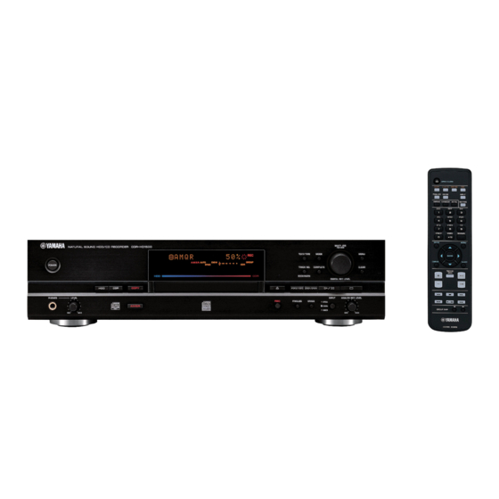
FRONT PANEL .............................................................. 5
REAR PANELS .......................................................... 5~6
REMOTE CONTROL PANEL ........................................ 6
SPECIFICATIONS ...................................................... 6~7
INTERNAL VIEW ........................................................... 7
DISASSEMBLY PROCEDURES / 分解手順 ............ 8~15
サービスチェック手順 ............................................ 16~19
INSPECTIONS / 検査 ............................................. 20~25
ファームウエアの更新 ......................................... 26~27
1 0 0 9 5 1
CDR-HD1500
Failure to follow appropriate service and safety procedures when servicing this product may result in personal
injury, destruction of expensive components, and failure of the product to perform as specified. For these reasons,
we advise all YAMAHA product owners that any service required should be performed by an authorized
YAMAHA Retailer or the appointed service representative.
The presentation or sale of this manual to any individual or firm does not constitute authorization, certification or
recognition of any applicable technical capabilities, or establish a principle-agent relationship of any form.
Static discharges can destroy expensive components. Discharge any static electricity your body may have
accumulated by grounding yourself to the ground buss in the unit (heavy gauge black wires connect to this buss).
Turn the unit OFF during disassembly and part replacement. Recheck all work before you apply power to the unit.
HDD/CD RECORDER
SERVICE MANUAL
・ CDR-HD1500には販売地域によりハードディスクドラ
イブが搭載されているものと、搭載されていないものが
あります。
・ 修理依頼を受ける際、HDDのデータは保証できないこ
とをお客様に伝えてください。
IMPORTANT NOTICE
FORMATTING THE HDD / HDDのフォーマット ........ 27
メインPCBへのID書き込み .................................... 28~29
DISPLAY DATA ..................................................... 30~31
IC DATA ................................................................. 32~39
BLOCK DIAGRAM ....................................................... 40
PRINTED CIRCUIT BOARD .................................. 41~44
SCHEMATIC DIAGRAM ........................................ 45~50
PARTS LIST ........................................................... 51~60
REMOTE CONTROL .................................................... 61
Parts List for Carbon Resistors ................................ 61
2005
All rights reserved.
P.O.Box 1, Hamamatsu, Japan
'05.04
Advertisement
Table of Contents

Related Manuals for Yamaha CDR-HD1500


Summary of Contents for Yamaha CDR-HD1500
-
Page 1: Table Of Contents
This manual has been provided for the use of authorized YAMAHA Retailers and their service personnel. It has been assumed that basic service procedures inherent to the industry, and more specifically YAMAHA Products, are already known and understood by the users, and have therefore not been restated. -
Page 2: To Service Personnel
CDR-HD1500 I TO SERVICE PERSONNEL AC LEAKAGE WALL EQUIPMENT TESTER OR 1. Critical Components Information OUTLET UNDER TEST EQUIVALENT Components having special characteristics are marked s and must be replaced with parts having specifications equal to those originally installed. 2. Leakage Current Measurement (For 120V Models Only) - Page 3 CDR-HD1500 WARNING: Laser Safety This product contains a laser beam component. This component may emit invisible, as well as visible radiation, which may cause eye damage. To protect your eyes and skin from laser radiation, the following precautions must be used during servicing of the unit.
-
Page 4: Prevention Of Electrostatic Discharge
CDR-HD1500 VARO!: A V A T T A E S S A J A S U O J A L U K I T U S O H I T E T T A E S S A O L E T A L T T I I N A N Ä... -
Page 5: Front Panel
CDR-HD1500 I FRONT PANEL CDR-HD1500 I REAR PANELS CDR-HD1500 (U model) CDR-HD1500 (A model) CDR-HD1500 (B, G models) -
Page 6: Remote Control Panel
....435 x 115.5 x 414.5 mm (17-1/8" x 4-1/2" x 16-5/16") (include legs, terminals and knobs) Weight / 質量 CDR-HD1500 without HDD ......8.2 kg (18 lbs. 1 oz.) AUDIO PERFORMANCE / オーディオ性能 Panel Color / パネル色 Output Level / 出力レベル (1kHz 0dB) ......2 ± 0.5 Vrms Gold Color ................. -
Page 7: Internal View
CDR-HD1500 • DIMENSIONS 435 (17-1/8") Unit : mm (inch) 単位: mm (インチ) I INTERNAL VIEW OSD (2) P.C.B. (U, J models) OPERATION (6) P.C.B. OPERATION (7) P.C.B. OSD (1) P.C.B. MAIN P.C.B. HDD UNIT OPERATION (1) P.C.B. WCLK P.C.B. OPERATION (2) P.C.B. -
Page 8: Disassembly Procedures / 分解手順
CDR-HD1500 I DISASSEMBLY PROCEDURES / 分解手順 (番号順に部品を取り外してください。) (Remove parts in the order as numbered.) CD-R/RW Drive Replacement CD-R/RWドライブの交換 • The CD-R/RW drive must be replaced as a unit. None ・ CD-R/RWドライブは、ユニット交換となります。小部 of its components can be supplied separately. 品の部品供給はできません。 • After replacing the CD-R/RW drive, be sure to update ・... - Page 9 CDR-HD1500 2. サブシャーシユニット、トレイガイドユニット、 2. Removal of Sub Chassis Unit, Tray Guide Unit and HDD Tray Unit HDDトレイユニットの取り外し a. 3 のネジ2本をゆるめ、HDDスロットドアを開きます。 a. Loosen 2 screws (3) and open the HDD slot door. (Fig. (Fig. 2) b. 4 のネジ2本を外します。 (Fig. 3) b. Remove 2 screws (4). (Fig. 3) HDD Slot Door HDDスロットドア...
- Page 10 CDR-HD1500 4. WCLK P.C.B.の取り外し 4. Removal of WCLK P.C.B. a. CB1、CB140 を外します。 (Fig. 5) a. Remove CB1 and CB140. (Fig. 5) d. 8 のネジ2本を外します。 (Fig. 5) d. Remove 2 screws (8). (Fig. 5) c. WCLK P.C.B.を取り外します。 (Fig. 5) c. Remove the WCLK P.C.B.. (Fig. 5) WCLK P.C.B.
- Page 11 CDR-HD1500 7. CDRユニットの組立 7. Assembly of CDR Unit After replacing the CD-R/RW drive, be sure to update the CD-R/RWドライブを交換したときには、CD-R/RWドライ CD-R/RW drive firmware to the latest version. ブファームウエアを最新版に更新してください。 a. 新しいCD-R/RWドライブのショートピンを、マスター a. Set the plastic shunt of the new CD-R/RW drive to the master position.
- Page 12 CDR-HD1500 HDD Replacement HDDの交換 a. Loosen 2 screws ( A ) and open the HDD slot door. (Fig. a. A のネジ2本をゆるめ、HDDスロットドアを開きます。 (Fig. 10) HDD Slot Door HDDスロットドア Fig. 10 b. H D D からI D Eケーブルと電源ケーブルを外します。 b. Disconnect the IDE cable and power cable from the HDD.
- Page 13 CDR-HD1500 e. 新しいHDDのショートピンを、スレーブの状態にしま e. Set the plastic shunt of the new HDD to slave. (Fig. 13) * It is necessary to set the HDD to MASTER or SLAVE す。 (Fig. 13) when connecting the HDD to the component you ※ IDE/ATAタイプのHDDはお使いになる機器と接続す...
- Page 14 CDR-HD1500 P.C.B. Operation Check P.C.B.動作チェック a. Remove the Top Cover. a. トップカバーを取り外します。 b. Loosen 2 screws (D) on the HDD slot door and open b. リアパネルのDのネジ2本をゆるめ、HDDスロットドア the HDD slot door. (Fig. 16) を開きます。 (Fig. 16) c. Remove 2 screws ( E ). (Fig. 17) c.
- Page 15 CDR-HD1500 i. Remove 3 screws ( G ) and 2 jack screws ( H ). (Fig. 19) i. G のネジ3本、 H のジャックスクリュー2 本を外しま j. Remove the OSD P.C.B.. (Fig. 20) す。 (Fig. 19) k. Remove 4 screws ( I ). (Fig. 20) j.
-
Page 16: Service Check Procedures
CDR-HD1500 I サービスチェック手順 I SERVICE CHECK PROCEDURES 本体が動作しない When the main unit fails to operate Check 全ケーブル ケーブルを接続し Reconnect cables connections の接続部を 直して再びチェック of all and check again. チェック する。 cables. する。 Check Check the condition 電源を 電源部に不具合が the power +5V, +12V, ±VA... - Page 17 CDR-HD1500 When ATAPI device is defective ATAPIデバイス不良 Possible symptom varies depending on the 不良個所により以下の症状が考えられます。 defective point. ・ 「Drive Check」 と表示される。 • “Drive Check” is displayed. ・ レベルメーターの目盛りだけが表示される。 • Only the scale of the level meter is displayed. ・ ドライブのスイッチを切り替えるとハングアップする。 • Switching the drive switch causes hang-up to occur.
- Page 18 CDR-HD1500 ACDR2 Check ACDR2不良 By using the mode 1, mode 2 and mode 3 of the P.C.B. P.C.B.テストモードのモード1、モード2およびモード3を test mode, the operation of the ACDR2 can be checked. 使用することにより、ACDR2の動作を確認することがで きます。 In Mode 1, the analog signal input/output operation is checked.
- Page 19 CDR-HD1500 モード2動作確認 Mode 2 Operation Check 1) Set to Mode 2 by pressing the “ ” key. “test 1) “ ” キーを押し、モード2 に設定します。 mode 2” is displayed, followed by “mod2 00 00 00”. 「test mode 2」 が表示された後、 「mod2 00 00:00」 が表...
-
Page 20: Inspections
CDR-HD1500 I INSPECTIONS Instruments Required for Inspection • CD test disc (YEDS-18: TX911730) • CD-RW disc (TDK CD-RW AUDIO 74min [XA74N]) • CD player with digital output (optical/coaxial) function (used as a digital signal generator) • AV amplifier with digital input (optical/coaxial) function (used as a D/A converter) •... - Page 21 CDR-HD1500 I 検査 準備するもの CDテストディスク (YEDS-18 : TX911730) CD-RWディスク (TDK CD-RW AUDIO 74min ( XA74N) ) デジタル出力 (光/同軸) を持ったCDプレーヤー (デジタル信号発生器として使用します) デジタル入力 (光/同軸) を持ったAVアンプ (D/A変換器として使用します) アナログ信号発振器、オシロスコープ、レベルメーター、歪率計 治具用HDD(HDD UNIT FOR SERVICE: AAX39420) 確認方法&規格 ステップ 項目 モード 入力信号 ディスク キーと キーを ディスプレイ テストモード...
- Page 22 CDR-HD1500 Step Mode Input signal Check method and standard Item Disc 1. Press the “MENU” key. DAC mode LINE IN (ANALOG) A/D converter No disc Turn the “MULTI JOG” knob to select 1kHz, 20Hz, 20kHz “DAC mode” then press the “MULTI JOG”...
- Page 23 CDR-HD1500 確認方法&規格 ステップ 項目 モード 入力信号 ディスク DACモード LINE IN (ANALOG) ADコンバータ No disc 1. MENUキーを押し、MULTI JOGを回して 「DAC mode」を選び、MULTI JOGを押す。 1kHz, 20Hz, 20kHz 2. INPUTセレクターをANALOGにする。 500mVrms 3. LINE IN (ANALOG)に1kHz, 500mVrmsのアナ ログ信号を加える。 4. DIGITAL OUT (COAXIAL)のデジタル信号をアナ ログに復調する。 5. ANALOG REC LEVELツマミを調整して、復調...
- Page 24 CDR-HD1500 Step Item Mode Input signal Disc Check method and standard Recording Normal mode No disc Execute HDD formatting when HDD for the jig External Input is installed. (Refer to “FORMATTING THE HDD” on page 27.) 1. Press the “HDD” key to select HDD.
- Page 25 CDR-HD1500 ステップ 項目 モード 入力信号 ディスク 確認方法&規格 外部入力から 製品モード No disc 治具用HDDを取り付けた場合には、HDDのフォー HDDへの録音 マットを行う。 ( 「HDDのフォーマット」 27ページ参照) 1. HDDキーを押しHDDを選択する。 2. RECキーを押す。 「0:00」 が表示される。 3. INPUTキーを押して録音する入力ソースを選択す る。 4. 録音レベルを調整する。 キーを押して録音を開始する。 6. 20秒以上録音し、 キーを押して録音を停止す る。 7. MULTI JOGを回して、先ほど録音したトラックを 選択する。 キーを押して再生し、正しく録音されてい ることを確認する。 CDプレーヤー...
-
Page 26: Updating Firmware
CDR-HD1500 I ファームウエアの更新 I UPDATING FIRMWARE 1. 概要 1. Overview MAIN P.C.B.またはIC11(MAIN P.C.B)またはCD-R/RWド After replacing the MAIN P.C.B. or the IC11(MAIN P.C.B) ライブを交換した場合、ファームウェアの更新が必要で or the CD-R/RW Drive, the firmware must be updated. す。ファームウエアには、システムコントロール ファーム Note that there are two types of firmware; system control ウエアとCD-R/RWドライブ... -
Page 27: Formatting The Hdd / Hddのフォーマット
2. After installing an HDD which has been used b.“ H D D ” キ ー を 押 し て ハ ー ド デ ィ ス ク を 選 択 し 、 for another CDR-HD1500, execute formatting “MENU” キーを押します。 according to the following procedure. -
Page 28: Entering Id To Main P.c.b
Items required: IC Writing Board with Jig Cable (2P) Parts No.: WA045500 CB4 is to select the I/O voltage. CB4 is to select the I/O voltage. On the CDR-HD1500 it is "+5V". On the CDR-HD1500 it is "+5V". CB4は、I/O電圧の選択用。 CB4は、I/O電圧の選択用。... - Page 29 4) “MULTI JOG” つまみを回して、 「Sys ID Write」 を選び and then press the “MULTI JOG” knob. ます。 5) Turn the “MULTI JOG” knob to select “CDR-HD1500” “MULTI JOG” つまみを押します。 depending on the model and then press the “MULTI 5) “M U L T I J O G ” つまみを回して、モデル名に応じて...
-
Page 30: Display Data
CDR-HD1500 I DISPLAY DATA G V400 : BJ992GN (V9468600) › G PIN CONNECTION Pin No. Connection Pin No. Connection Note : 1) F1, F2 ..Filament 2) NP ..No pin 3) NX ..No extend pin 4) DL ..Datum Line 5) 1G ~ 16G .. - Page 31 CDR-HD1500 G ANODE CONNECTION 13G 14G – – – RB10 – RB11 – LB10 LB11 – – – – – – – – – – – – – – – – – – – – – – – – –...
-
Page 32: Ic Data
CDR-HD1500 I IC DATA IC2 : HD6417014F28 (MAIN P.C.B.) µ-COM (CPU) PE0/TIOC0A/DREQ0 PE1/TIOC0B/DRAK0 PE2/TIOC0C/DREQ1 PE3/TIOC0D/DRAK1 PE4/TIOC1A PA0/RXD0 PF0/AN0 PA1/TXD0 PF1/AN1 PA2/SCK0/DREQ0/IRQ0 PF2/AN2 PA3/RXD1 PF3/AN3 PA4/TXD1 PF4/AN4 PA5/SCK1/DREQ1/IRQ1 PF5/AN5 PA6/TCLKA/CS2 HD6417014F28 AVss PA7/TCLKB/CS3 PF6/AN6 PA8/TCLKC/IRQ2 PF7/AN7 PA9/TCLKD/IRQ3 AVcc PE5/TIOC1B PE6/TIOC2A PE7/TIOC2B... - Page 33 CDR-HD1500 IC2 : HD6417014F28 (MAIN P.C.B.) µ-COM (CPU) Port Name Function +5V power supply Address bus /RAS N_RAS DRAM control /CASL N_CASL DRAM control /CASH N_CASH DRAM control RDWR RDWR DRAM control Address bus Address bus /WAIT N_WAIT WAIT input...
- Page 34 CDR-HD1500 IC2 : HD6417014F28 (MAIN P.C.B.) µ-COM (CPU) Port Name Function NMI input +5V Power Supply Setting CPU operation mode Setting CPU operation mode PLLVCC +5V Power Supply PLLCAP PLL Capacitor Terminal PLLVSS Peripheral device clock /RES Reset input TIOC0A...
- Page 35 CDR-HD1500 IC3 : YDC126-F (MAIN P.C.B.) ACDR MUTAE MUTSP /CAS /WAIT /RAS /IRQ /RWE FSCNT /ROE RA10 YDC126-F RA11 RA12 SRCD1 RD10 RD11 RD12 RD13 RD14 RD15 Name DC Level Function Microprocessor interface, chip select input Microprocessor interface, read strobe input...
- Page 36 CDR-HD1500 IC3 : YDC126-F (MAIN P.C.B.) ACDR Name DC Level Function (Unconnected) General purpose input port General purpose input port General purpose input port General purpose input port General purpose input port General purpose input port (Unconnected) General purpose input port...
- Page 37 CDR-HD1500 IC3 : YDC126-F (MAIN P.C.B.) ACDR Name DC Level Function External RAM interface, data bus External RAM interface, data bus Power supply +5V RA12 External RAM interface, address output (Unconnected) RA11 External RAM interface, address output (Unconnected) RA10 External RAM interface, address output (Unconnected)
- Page 38 CDR-HD1500 IC401 : M66005-0141AFP (OPERATION P.C.B.) FL tube driver Display code RAM CGROM SEG00 Bank 1 : 8bit x 16 (35bit x 160) Bank 2 : 8bit x 64 Segment 33 SEG26 output code circuit SEG27 write CGRAM dot data...
- Page 39 CDR-HD1500 IC401 : M66005-0141AFP (OPERATION P.C.B.) FL tube driver Name IN/OUT Function DIG01 Digit output DIG00 Digit output /RESET Reset input Chip select input Shift clock input SDATA Serial data input Universal port Universal port VCC1 Positive power supply for internal logic...
-
Page 40: Block Diagram
CDR-HD1500 I BLOCK DIAGRAM... -
Page 41: Printed Circuit Board
CDR-HD1500 I PRINTED CIRCUIT BOARD (Foil side) • Semiconductor Location Ref. No. Location Ref. No. Location Ref. No. Location Ref. No. Location IC200 IC201 CD-R/RW Drive & HDD IC202 Refer to “Starting the P.C.B. Test Mode” on page 18. D200... - Page 42 CDR-HD1500 I PRINTED CIRCUIT BOARD (Foil side) • Semiconductor Location Ref. No. Location D400 OPERATION (1) P. C. B. (Side A) D401 D402 IC400 IC401 Q400 MAIN Q401 (CB3) Q402 Q403 Q404 Q405 Q406 Q407 48 49 Q408 MULTI JOG...
- Page 43 CDR-HD1500 I PRINTED CIRCUIT BOARD (Foil side) Lead Free Solder Used • Semiconductor Location Ref. No. Location D490 D491 OPERATION (2) P. C. B. OPERATION (3) P. C. B. OPERATION (4) P. C. B. OPERATION (7) P. C. B. D495...
- Page 44 CDR-HD1500 I PRINTED CIRCUIT BOARD (Foil side) OSD (1) P. C. B. (Side A) OSD (1) P. C. B. (Side B) Lead Free Solder Used WCLK P. C. B. (Side A) RS-232C VIDEO VIDEO S VIDEO MAIN SB_DATA (CB1) (CB140)
-
Page 45: Schematic Diagram
CDR-HD1500 SCHEMATIC DIAGRAM (MAIN 1/2) Point Pin 74 of IC2 DRAM CLOCK Point Pin 129 of IC3 ACDR Point VCC of IC4 and OUT of IC4 ANALOG OUT (DIGITAL) -4.9 POWER ON Ch 1 Ch 2 IC202: NJM2904M SYSTEM Dual OP-Amp V–... - Page 46 CDR-HD1500 SCHEMATIC DIAGRAM (MAIN 2/2) Page 47 to OPERATION (1) OPTICAL DIGITAL ANALOG L / R BUFFER COAXIAL MIXER ANALOG L / R OPTICAL DIGITAL 24 BIT CODEC COAXIAL -4.9 -4.9 MUTE -4.9 -4.9 -5.0 ANALOG OUT -4.9 -4.9 -4.9 -4.7...
- Page 47 CDR-HD1500 SCHEMATIC DIAGRAM (OPERATION 1/2) FL TUBE -22.2 -22.2 FL TUBE DRIVER DECODER/ DEMULTIPLEXERS -22.2 -22.2 -28.2 IC400: HD74HC139FPEL Dual 2 line to 4 line Decoders/Demultiplexers ENABLE SELECT INPUTS ENABLE SELECT INPUTS REMOTE CONTROL PIN CONNECTION DIAGRAM OF TRANSISTORS, RECEIVER DIODES AND ICS.
- Page 48 CDR-HD1500 SCHEMATIC DIAGRAM (OPERATION 2/2) IC500: µPC4570HA IC700~701 : PQ1CG2032FZ Dual OP-Amp Voltage Regulator Voltage ON/OFF regulator circuit PWM COMP. ON/OFF – Vcc Vo Soft start Oscillator Over current protection circuit ERROR AMP. – Oadj Over heat protection circuit IC702: M5237L...
- Page 49 CDR-HD1500 I SCHEMATIC DIAGRAM (OSD) U, J models only RS-232C DRIVER/RECEIVER -8.1 5.1 5.0 0 -8.1 0 5.0 x :NOT USED OSD (2) O :USED / APPLICABLE -2.4 4.8 -4.2 -8.1 -8.1 PIN CONNECTION DIAGRAM OF TRANSISTORS, DIODES AND ICS.
- Page 50 CDR-HD1500 I SCHEMATIC DIAGRAM (WCLK) IC801: SN74LV393ANSR IC802: TC74HCU04AFEL Dual 4-Bit Binary Counters Hex Inverters 1CLK 1CLR 2CLK 2CLR PIN CONNECTION DIAGRAM OF TRANSISTORS, DIODES AND ICS. SN74LV393ANSR TC74HCU04AFEL WCLK # All voltage are measured with a 10MΩ/V DC electric volt meter.
-
Page 51: Parts List
CDR-HD1500 PARTS LIST I ELECTRICAL PARTS I WARNING Components having special characteristics are marked s and must be replaced with parts having specifications equal to those originally installed. ● 印のある部分は、 安全確保部品を示しています。 部品の交換が必要な場合、 パーツリス トに記載されている部品を使用してく ださい。 ●部品価格ランクは、 予告なく変更することがあり ます。 ABBREVIATIONS IN THIS LIST ARE AS FOLLOWS: C.A.EL.CHP... - Page 52 CDR-HD1500 P.C.B. MAIN Ref. Part No. Description Remarks Markets 部 品 名 Rank WF002400 P.C.B. MAIN PCB メイン V4325300 CグリッドSLヘッダ 01 VL845300 CN.BS.PIN ベース付ポスト VP082900 CN.BS.PIN FFCコネクター V6451700 CN.BS.PIN 16P TE ピンヘッダー VB389800 CN.BS.PIN ベースピン CB140 VB390000 CN.BS.PIN ベースピン CB200 WB920900 CN.PHOT.SN 1P GP1FA513TZ0F 光ファイバデータ端子...
- Page 53 CDR-HD1500 P.C.B. MAIN & P.C.B. OPERATION Ref. Part No. Description Remarks Markets 部 品 名 Rank IC202 XV190A00 NJM2904M OP AMP アンプIC IC203-204 XQ185A00 NJM2100M IC IC205 X2331A00 NJM4580E OP AMP アンプIC SOP 01 IC206 XG903A00 TC4052BF MPX IC IC208 XW526A00 YSD917 IC...
- Page 54 CDR-HD1500 P.C.B. OPERATION Ref. Part No. Description Remarks Markets 部 品 名 Rank C505 VJ599100 C.CE.TUBLR 0.1uF 円筒セラコン C506 UR838330 C.EL 330uF ケミコン s C550 V3501400 C.CE.SAFTY 0.01uF 275V 規格認定コン s C600-601 V3501400 C.CE.SAFTY 0.01uF 275V 規格認定コン C700-703 UA654100 C.MYLAR 0.01uF マイラーコン...
- Page 55 CDR-HD1500 P.C.B. OPERATION Ref. Part No. Description Remarks Markets 部 品 名 Rank D722-723 VU264100 DIODE 1SR139-400 ダイオード s D750-751 VU264100 DIODE 1SR139-400 ダイオード D752 VG439800 DIODE.ZENR MTZJ11A ツェナーダイオード 01 D753-754 VU264100 DIODE 1SR139-400 ダイオード IC400 XU532A00 HD74HC139FPEL 2-4 ロジックIC SOP 02 IC401...
- Page 56 CDR-HD1500 P.C.B. OPERATION & P.C.B. OSD & P.C.B. WCLK Ref. Part No. Description Remarks Markets 部 品 名 Rank V400 V9468600 FL.DSPLY BJ992GN 螢光表示管 VR400 V6619600 B50KΩ RK14K12C0 二連ロータリーVR 03 VR500 V7502400 A20KΩ RK09L12B0 二連ロータリーVR 04 VQ859800 SHEET シート/FL V8080700 SPACER.FL スペーサ/FL ...
- Page 57 CDR-HD1500 Chip Parts Chip Parts Ref. Ref. Part No. Description Remarks Markets 部 品 名 Rank Part No. Description Remarks Markets 部 品 名 Rank UF017470 C.EL.CHP 47uF 6.3V チップケミコン RD359100 R.CHP 1MΩ 1/16W J チップ抵抗 UF018100 C.EL.CHP 100uF 6.3V チップケミコン RF356470 R.MTL.CHP 4.7KΩ...
- Page 58 CDR-HD1500 I EXPLODED VIEW U, J models 200-1 U, J models 1-42 12 (5) 1-25 12 (4) 1-36 1-45 1-41 1-31 1-30 1-42 1-21 12 (3) 7-21 1-42 1-30 7-21 1-17 1-18 1-42 1-13 12 (2) 12 (1) 1-42 1-28...
- Page 59 CDR-HD1500 I MECHANICAL PARTS Ref. Ref. Part No. Description Remarks Markets 部 品 名 Rank Part No. Description Remarks Markets 部 品 名 Rank WB128100 FLEXIBLE FLAT CABLE 25P 420mm P=1.25 カード電線 C&C V9857800 TOP COVER トップカバー VQ368600 PUSH RIVET P3555-B プッシュリベット V7354300 TOP COVER トップカバー...
- Page 60 CDR-HD1500 I HDD TRAY UNIT I HDD TRAY UNIT 6-13 6-22 Ref. Part No. Description Remarks Markets 部 品 名 Rank V9479200 FRAME SIDE/R フレーム サイド/R V9479300 FRAME SIDE/L フレーム サイド/L V9478800 WASHER/SIDE ワッシャー/サイド 6-21 6-12 V9597400 WASHER/B ワッシャ/B 6-22 6-11 V9569400 STOPPER ストッパー/トレイ...
-
Page 61: Remote Control
CDR-HD1500 Parts List for Carbon Resistors I REMOTE CONTROL SCHEMATIC DIAGRAM Value 1/4W Type Part No. 1/6W Type Part No. Value 1/4W Type Part No. 1/6W Type Part No. 1.0 Ω 3100 3100 10 kΩ 7100 7100 HJ35 HF85 HF45 HF45 1.8 Ω... - Page 62 CDR-HD1500...