Table of Contents
Advertisement
Quick Links
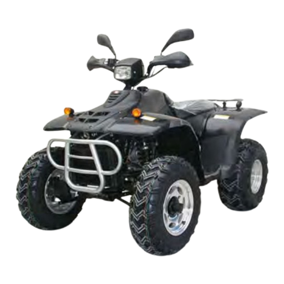
2007 ATV
SERVICE MANUAL
ATV 260/300
●
Model : 2004
2005
Special Edition - Anniversary
2x4
4x4
B-Type ATV 150/200, 2x4
●
B-Type ATV 260/300, 2x4/ 4x4
●
Youth ATV 50/80
●
WARNING
The parts of different types/ variants/ versions maybe un-interchangeable, even some parts
have almost same appearance. Always refer to Parts Manual of each ATV model for spare
parts information and service.
USA 07.0
PN. F010103A01
※
※
Engine
※
※
※
※
※
※
Advertisement
Table of Contents
Troubleshooting

Related Manuals for Linhai ATV 260


Summary of Contents for Linhai ATV 260
- Page 1 ● Model : 2004 2005 Special Edition - Anniversary B-Type ATV 150/200, 2x4 ● B-Type ATV 260/300, 2x4/ 4x4 ● Youth ATV 50/80 ● WARNING The parts of different types/ variants/ versions maybe un-interchangeable, even some parts have almost same appearance. Always refer to Parts Manual of each ATV model for spare parts information and service.
- Page 2 Foreword This manual is designed primarily for use by the ATV factory certified service technicians in a properly equipped shop. Persons using this manual should have a sound knowledge of mechanical theory, tool use, and shop procedures in order to perform the work safely and correctly.
- Page 3 CONTENTS ↖ CHAPTER1 ………………………………………………General Information ↖ CHAPTER2 ………………………………………….……………Maintenance ↖ CHAPTER3A…………………………………….……….….…260 300 Engine ↖ CHAPTER3B…………………………………….……….…….…50 80 Engine ↖ CHAPTER3C……………………………………. …. 100 125 150 200Engine ↖ CHAPTER4A…………………………………………..…………………Chassis ↖ CHAPTER4B………………………..……………Chassis (Youth/ mini ATV) ↖ CHAPTER5………………………………………………….………Final Drive ↖ CHAPTER6……………………………………………….………Transmission ↖ CHAPTER7………………………………………………………………Brakes ↖ CHAPTER8………………………………………………….….………Electrical...
- Page 4 WARNING Never run an engine in an enclosed area. Carbon monoxide exhaust gas is poisonous and can cause severe injury or death. Always start engines outdoors. Gasoline is extremely flammable and explosive under certain conditions. Battery electrolyte is poisonous. It contains sulfuric acid. Serious burns can result from contact with skin, eyes or clothing.
- Page 5 CHAPTER 1 GENERALINFORMATION ATV SERVICE MANUAL 07.0 CHAPTER 1 GENERAL INFORMATION WARNING The parts of different types/ variants/ versions maybe un-interchangeable, even some parts have almost same appearance. Always refer to Parts Manual of each ATV model for spare parts information and service.
- Page 6 CHAPTER 1 GENERALINFORMATION ATV SERVICE MANUAL 07.0 1.1 IMPORTANT INFORMATION PREPARATION FOR REMOVAL PROCEDURES 1. Remove all dirt, mud, dust and foreign material before removal and disassembly. 2. Use proper tools and cleaning equipment. 3. When disassembling the machine, always keep mated parts together. This includes gears, cylinders, pistons and other parts that have been ”mated ”through normal wear.
-
Page 7: Chapter 1 General Page
CHAPTER 1 GENERALINFORMATION ATV SERVICE MANUAL 07.0 Always replace piston pin clips after one use. Replace distorted circlips. When installing a circlip① , make sure that the sharp-edged corner ② is positioned opposite the thrust ③ it receives. See sectional view. ④Shaft CHECKING OF CONNECTIONS Dealing with stains, rust, moisture, etc. - Page 8 CHAPTER 1 GENERALINFORMATION ATV SERVICE MANUAL 07.0 CONVERSION TABLE How to use the CONVERSION TABLE Use this table to convert METRIC unit data to IMPERIAL unit data. METRIC MULIPLIER **mm 0. 3937 **in **cm 0.03937 **in CONVERSION TABLE METRIC TO IMP Known Multiplier Result...
- Page 9 CHAPTER 1 GENERALINFORMATION ATV SERVICE MANUAL 07.0 V.I.N AND ENGINE SERIAL NUMBER ATV 260 / 300 Mini / Youth PAGE. 1- 5 CHAPTER 1 GENERAL...
- Page 10 CHAPTER 1 GENERALINFORMATION ATV SERVICE MANUAL 07.0 VEHICLE DIMENSIONS 2004 2005 Special Edition - Anniversary DEMON Mini / Youth B-Type Note. The on-road equipments (rear view mirror, turn lights, etc.) are not Standard Equipment for USA. PAGE. 1- 6 CHAPTER 1 GENERAL...
- Page 11 CHAPTER 1 GENERALINFORMATION ATV SERVICE MANUAL 07.0 ATV 260 / 300 ’05 Model ATV 260 / 300 PAGE. 1- 7 CHAPTER 1 GENERAL...
- Page 12 CHAPTER 1 GENERALINFORMATION ATV SERVICE MANUAL 07.0 Demon ATV 260 / 300 Europe Mini / Youth PAGE. 1- 8 CHAPTER 1 GENERAL...
- Page 13 CHAPTER 1 GENERALINFORMATION ATV SERVICE MANUAL 07.0 Special Edition - Anniversary B-Type 260/ 300 PAGE. 1- 9 CHAPTER 1 GENERAL...
- Page 14 CHAPTER 1 GENERALINFORMATION ATV SERVICE MANUAL 07.0 B-Type 150/ 200 PAGE. 1- 10 CHAPTER 1 GENERAL...
- Page 15 CHAPTER 1 GENERALINFORMATION ATV SERVICE MANUAL 07.0 NOTES PAGE. 1- 11 CHAPTER 1 GENERAL...
- Page 16 CHAPTER 2 MAINTENANCE ATV SERVICE MANUA 07.0 CHAPTER 2 MAINTENANCE WARNING The parts of different types/ variants/ versions maybe un-interchangeable, even some parts have almost same appearance. Always refer to Parts Manual of each ATV model for spare parts information and service. 2.1 PERIODIC MAINTENANCE 2.2 FUEL SYSTEM 2.3 TOE ALIGNMENT...
-
Page 17: Periodic Maintenance
CHAPTER 2 MAINTENANCE ATV SERVICE MANUA 07.0 2.1 PERIODIC MAINTENANCE GENARAL CAUTION Mark on the following chart DL :Due to the nature of the adjustments marked with a DL on the following chart, it is recommended that service be performed by an authorized dealer. ▲:... - Page 18 CHAPTER 2 MAINTENANCE ATV SERVICE MANUA 07.0 Coolant strength 25 hrs 3 months Inspect strength seasonally ▲ Air Box Sediment Tube Daily Headlamp Inspection Daily apply dielectric grease to connector when replaced Tail lamp inspection Daily apply dielectric grease to socket when replaced ▲...
- Page 19 CHAPTER 2 MAINTENANCE ATV SERVICE MANUA 07.0 Throttle Cable Pre-ride Grease M) Throttle Cable 50 hrs 6 months A L ( R if necessary Shift linkage 50 hrs 6 months I A R if necessary Transmission belt 50 hrs 6 months if necessary ▲...
- Page 20 CHAPTER 2 MAINTENANCE ATV SERVICE MANUA 07.0 (H/L/R/N) Brake fluid Level Pre-ride Brake fluid 200 hrs 24 months Change every two years Idle Speed Required Toe adjustment Periodic inspection, adjust when parts are Required replaced Headlight Aim Adjust if necessary Required ▲...
- Page 21 CHAPTER 2 MAINTENANCE ATV SERVICE MANUA 07.0 Post Bushings pivot shaft and hours grease with grease gun ▲ 8.Front Wheel Grease Inspect and replace bearings if Semi-annually bearings (high temperature necessary resist) 9.Tie rods Grease Locate fittings and grease Semi-annually 10.Shift Grease Locate fittings and grease...
-
Page 22: Fuel System
CHAPTER 2 MAINTENANCE ATV SERVICE MANUA 07.0 LUBRICATION RECOMMENDATIONS NOTE: 1. More often under severe use, such as wet or dusty conditions. 2. Grease: Light weight lithium-soap grease. 3. Grease M:Molybdenum disulfide (MoS ) grease (water resistant). 4. *When suspension action becomes stiff or after washing. 5. - Page 23 Never start the engine or let it run in an enclosed area. Gasoline powered engine exhaust fumes are poisonous and can cause loss of consciousness and death in a short time. Never drain the float bowl when the engine is hot. Severe burns may result. ATV 260/ 300 YOUTH/ MINI ATV CHAPTER 2 MAINTENANCE PAGE.
- Page 24 The fuel filter should be replaced in accordance with the Periodic Maintenance Chart or whenever sediment is visible in the ATV 260/ 300 filter. 1. Shut off fuel supply at fuel valve. 2. Remove line clamps at both ends of the filter.
- Page 25 CHAPTER 2 MAINTENANCE ATV SERVICE MANUA 07.0 FOR B-TYPE ATV Fuel strainer screen cleaning: 1. Remove the fuel tank. 2. Drain the gasoline into an approved fuel container. Remove the two mounting bolts, collars and the fuel valve. 3. Remove the O-ring and fuel strainer screen.
-
Page 26: Toe Alignment
CHAPTER 2 MAINTENANCE ATV SERVICE MANUA 07.0 2.3 TOE ALIGNMENT METHOD: STRAIGHTEDGE OR STRING Be sure to keep handlebars centered NOTE: String should just touch side surface of rear tire on each side of the ATV. Measure from string to rim at front and rear of rim. - Page 27 Check friction pads for wear, damage and looseness. Check surface condition of the disc. BRAKE PAD INSPECTION Foot control brake is only for ATV 260 / 300 Pads should be changed when friction material is worn to 3/64" (1mm). HOSE/FITTING INSPECTION...
- Page 28 MECHANICS PARKING BRAKE EUROPE ATV 260 / 300 Checking Although the parking brake has been adjusted at the factory, the brake should be checked for proper operation. The mechanical brake must be maintained to be ↑adjust on the lever...
- Page 29 5. Make sure the rear wheels turns freely ↑ adjust on the caliper without dragging. ATV 260/300 6. Turn the adjustor (the one on the lever) and apply the lever. While adjusting, it is important you apply the lever back and forth for operation, free play and the locking of the parking position.
- Page 30 CHAPTER 2 MAINTENANCE ATV SERVICE MANUA 07.0 DRUM BRAKE FOR ATV 50-150 The front brakes are located on the right handlebar. and are operated by the right hand. The front brakes are mechanical drum type brakes which are activated by one lever only.
- Page 31 CHAPTER 2 MAINTENANCE ATV SERVICE MANUA 07.0 the rock arm on the lever balance until 1/8” (2to3mm) free play is achieved at the brake lever. NOTE: While adjusting free play, it is important you apply the lever back and forth. 3.
- Page 32 CHAPTER 2 MAINTENANCE ATV SERVICE MANUA 07.0 2.5 SUSPENSION SPRING RPELOAD ADJUSTMENT Operator weight and vehicle loading affect suspen ents. Adjust sion spring preload requirem sary. neces FRONT SUSPENSION Compress and release front suspension. Damping should be smooth throughout the range of travel.
- Page 33 ATV 260 / 300 and B-Type: and rotation arrows on the tire point toward rotation. 2. Attach the wheel nuts (for ATV 260 / 300 and B-Type) / bolts ( for ATV 50-150) and finger tighten them. Install as shown (for ATV 260 / 300 and B-Type) at right for front or rear wheels.
- Page 34 CHAPTER 2 MAINTENANCE ATV SERVICE MANUA 07.0 end of nut goes into taper on wheel. CAUTION: If wheels are improperly installed it could affect Vehicle handling and tire wear. Tire Pressure Inspection 2.7 TIRE PRESSURE Front Rear TIRE INSPECTION CAUTION : 260/300 4PSI 4PSI...
- Page 35 2.8 FRAME , NUTS, BOLTS, FASTENERS Periodically inspect the tightness of all fasteners in accordance with the maintenance schedule. Check that all cotter pins are in place. Refer to specific fastener torques listed in each chapter. ATV 260 / 300 and B-Type Torque (Ft-Lb) Item...
- Page 36 CHAPTER 2 MAINTENANCE ATV SERVICE MANUA 07.0 EARLY DESIGN* Bolt M10 Attaching A-Arm and LT*/ Only ATV 260 early Frame model MANTENANCE-FREE PIVOT DESIGN Bolt M12 37-44 50-60 Attaching A-Arm and Frame Nut M10X1.25 Attaching A-Arm to Ball Joint Stud...
- Page 37 CHAPTER 2 MAINTENANCE ATV SERVICE MANUA 07.0 NOTES CHAPTER 2 MAINTENANCE PAGE. 2- 22...
-
Page 38: Chapter 3 Engine Page. 3A
CHAPTER 3A ENGINE 260/ 300 cc ATV SERVICE MANUAL07.0 CHAPTER 3 A ENGINE 260cc / 300 cc 3.1 MAINTENANCE SPECIFICATIONS 3.1.1 SPECIFICATIONS 3.1.2 TIGHTENING TORQUES 3.2 PARTS INSPECTION AND SERVICE 3.2.1 VALVE CLEARANCE ADJUSTMENT 3.2.2 IDLING SPEED ADJUSTMENT 3.2.3 SPARK PLUG INSPECTION 3.2.4 COMPRESSION PRESSURE 3.2.5 ENGINE OIL LEVEL INSPECTION 3.2.6 COOLANT LEVEL INSPECTION... - Page 39 CHAPTER 3A ENGINE 260/ 300 cc ATV SERVICE MANUAL07.0 3.1 MAINTENANCE SPECIFICATIONS 3.1.1SPECIFICATIONS Item Standard Limit Cylinder head : 0.03 mm Warp limit Cylinder: 260:70.000- 70.014 mm 260:70.025 mm Bore size 300:72.500- 72.514 mm 300;72.525 mm Out of round limit 0.03 mm Camshaft: Cam dimensions...
- Page 40 CHAPTER 3A ENGINE 260/ 300 cc ATV SERVICE MANUAL07.0 Standard Limit I t e m Stem-to-guide clearance 0.010- 0.037 mm 0.08 mm 0.025-0.052 mm 0.1 mm Stem runout limit … 0.01 mm 0.9-1.1 mm 1.6 mm Valve seat width 0 .9-1.1 mm 1.6 mm Valve spring : Free length (Inner)
- Page 41 CHAPTER 3A ENGINE 260/ 300 cc ATV SERVICE MANUAL07.0 Big end side clearance "D" 0.03 mm … 0.35- 0.85 mm … Standard Limit I t e m Automatic centrifugal clutch: 3.0 mm 2.0 mm Clutch shoe thickness 135 mm 135 .5 mm Clutch hosing inside diameter 2 8.1 mm …...
- Page 42 CHAPTER 3A ENGINE 260/ 300 cc ATV SERVICE MANUAL07.0 Standard Limit I t e m Radiator: Type Cooling fin with electric fan … Width/height/thickness 288/238/42 mm … Radiator cap opening pressure … 110-140kPa (1.1-1.4kg/cm 1.1-1.4bar) Radiator capacity … Reservoir tank capacity 0 .35 L …...
- Page 43 CHAPTER 3A ENGINE 260/ 300 cc ATV SERVICE MANUAL07.0 3.1.2TIGHTENING TORQUES Tightening Part name Thread Part to be tightened Q’ty Remarks Torque size m.kg Oil check bolt Exhaust pipe stud bolt Spark plug Cam sprocket cover Bolt Cylinder head and cylinder 2 .2 Cylinder head and cylinder Bolt...
- Page 44 CHAPTER 3A ENGINE 260/ 300 cc ATV SERVICE MANUAL07.0 Tightening Part to be tightened Part name Thread Q’ty Remarks torque size m.kg Cover (oil pump) Bolt P lug M 16 0 .8 Timing check plug One way clutch Bolt M 14 Clutch housing 0 .3 Grease stopper (Primary sheave)
-
Page 45: Chapter 3 Engine Page
CHAPTER 3A ENGINE 260/ 300 cc ATV SERVICE MANUAL07.0 3.2 PARTS INSPECTION AND SERVICE 3.2.1VALVE CLEARANCE ADJUSTMENT NOTE: Valve clearance adjustment should be made with the engine cool, at room temperature. When the valve clearance is to be measured or adjusted, the piston must be at Top Dead Center (T.D.C.) on the compression. - Page 46 CHAPTER 3A ENGINE 260/ 300 cc ATV SERVICE MANUAL07.0 Measure the valve clearance. If the clearance is incorrect, repeat above steps until specified clearance is obtained. 7. Install: Valve cover (intake side) O-ring 8 . Install: Valve cover(exhaust side) O-ring Spark plug Timing check window screw Crankcase cover...
- Page 47 CHAPTER 3A ENGINE 260/ 300 cc ATV SERVICE MANUAL07.0 1.Remove : Spark plug cap Spark plug CAUTION: Before removing spark plug, compressed blow away dirt accumulated in the spark plug wells to prevent it from falling into the cylinder. 1. Check: Spark plug type Incorrect Replace.
- Page 48 CHAPTER 3A ENGINE 260/ 300 cc ATV SERVICE MANUAL07.0 NOTE : Insufficient compression pressure will result in performance loss. 1. Check: Valve clearance Out of specification Adjust. Refer to “CALCE CLEARANCE ADJUSTMENT” section. 2. Start the engine and let it warm up for several minutes.
- Page 49 CHAPTER 3A ENGINE 260/ 300 cc ATV SERVICE MANUAL07.0 1,120 kP a (11.2 kg /cm , 11.2 bar) Measurement steps : Crank the engine with the throttle wide open until reading on the compression gauge stabilizes. WARNING : Before cranking the engine, ground all spark plug leads to prevent sparking.
- Page 50 CHAPTER 3A ENGINE 260/ 300 cc ATV SERVICE MANUAL07.0 inspecting the oil level. ENGINE OIL REPLACEMENT 1. Start the engine and let it warm up for several minutes . 2. Turn off the engine and place an oil pan under the engine.
- Page 51 CHAPTER 3A ENGINE 260/ 300 cc ATV SERVICE MANUAL07.0 CAUTION: Start the engine and check the oil pressure with the oil check bolt loosened. Do not apply at high speeds more than specified when checking the pressure. NOTE: Wipe any spilled oil off the engine. 3.2.6COOLANT LEVEL INSPECTION Inspect: Coolant level...
- Page 52 CHAPTER 3A ENGINE 260/ 300 cc ATV SERVICE MANUAL07.0 WARNING: Do not remove the radiator cap when the engine and radiator are hot. Scalding hot fluid and steam may be blown out under pressure, which could cause serious injury. When the engine has cooled, open the radiator cap as follows: Place a thick rag or a towel over the radiator cap.
- Page 53 CHAPTER 3A ENGINE 260/ 300 cc ATV SERVICE MANUAL07.0 containing corrosion inhibitors aluminum engine. and water ③ (soft water) : Coolant Mixed ratio: min50% /max50% follow the instruction of the coolant Total amount: Reservoir tank capacity: 0.35L Handling notes for coolant: Coolant is potentially harmful and should be handled with special care.
-
Page 54: Chapter 3A Engine 260/ 300 Cc Atv Service
CHAPTER 3A ENGINE 260/ 300 cc ATV SERVICE MANUAL07.0 Wait a few minutes until the coolant settles before inspecting the coolant level. 13. Install: Remain parts. 3.3CYLINDER HEAD Order Job name / Part name Q ’ty Remarks CHAPTER 3 ENGINE PAGE. - Page 55 CHAPTER 3A ENGINE 260/ 300 cc ATV SERVICE MANUAL07.0 Cylinder head removal Remove the parts in order. Drain the coolant. Side panel Footrest board Carburetor Thermo unit lead Refer to "CARBURETOR" Plug cap section . Crankcase breather hose Outlet hose (cylinder head) Breather hose (crankcase) Carburetor joint Joint...
- Page 56 CHAPTER 3A ENGINE 260/ 300 cc ATV SERVICE MANUAL07.0 (with stationary pointer ○ on the crankcase cover ) NOTE: If any special mark found, contact the ATV manufacture via the agent for the parts and special instruction. NOTE: Turn the primary sheave counterclockwise with a wrench and align the "I"...
- Page 57 CHAPTER 3A ENGINE 260/ 300 cc ATV SERVICE MANUAL07.0 3. Measure: Cylinder head warpage Out of secification → Resurface . Cylinder head warpage : Less than 0.03 mm Warpage measurement and resurfacement steps: Place a straight edge and a feeler gauge across the cylinder head.
- Page 58 CHAPTER 3A ENGINE 260/ 300 cc ATV SERVICE MANUAL07.0 Fit the timing chain onto the cam sprocket and install the cam sprocket on the camshaft. NOTE: When installing the cam sprocket, keep the timing chain as tense as possible on the exhaust side.
- Page 59 CHAPTER 3A ENGINE 260/ 300 cc ATV SERVICE MANUAL07.0 Out of specification → Adjust. Refer "VALVE CLEARANCE ADJUSTMENT"section. 3.4CAMSHAFT AND ROCKER ARMS Order Job name / Part name Q ’ty Remarks Remove the parts in order. Cam shaft and rocker arms removal Refer to "CYLINDER HEAD"...
- Page 60 CHAPTER 3A ENGINE 260/ 300 cc ATV SERVICE MANUAL07.0 Reverse the removal procedure for installation ROCKER ROCKER SHAFTRE MOVAL 1. Remove: Rocker arm shaft (intake) Rocker arm shaft (exhaust) NOTE: Attach a rocker arm shaft puller bolt weight to the rocker arm shaft and slide out the shaft.
- Page 61 CHAPTER 3A ENGINE 260/ 300 cc ATV SERVICE MANUAL07.0 Replace. Inspection steps: Inspect the two contact areas on the rocker arms for signs of unusual wear. Rocker arm shaft hole. Cam-lobe contact surface. Excessive wear → Replace. Inspect the surface condition of the rocker arm shafts.
- Page 62 CHAPTER 3A ENGINE 260/ 300 cc ATV SERVICE MANUAL07.0 4. Install: Rocker arm Rocker arm shaft (exhaust) NOTE: Exhaust: Install the rocker arm shaft (exhaust) completely pushed in. 5. Install: Rocker arm Rocker arm shaft (intake) NOTE: Intake: Insert the guide shaft (8 mm) into the stud bolt hole in the cylinder head to the rocker arm shaft (intake).
- Page 63 CHAPTER 3A ENGINE 260/ 300 cc ATV SERVICE MANUAL07.0 Order Job name / Part name Q ’ty Remarks Valves and valve springs removal Remove the parts in order. Cylinder head Refer to "CYLINDER HEAD " section . Rocker arm , rocker arm shaft Refer to "ROCKER ARM SHAFT AND ROCKER ARMS"...
- Page 64 CHAPTER 3A ENGINE 260/ 300 cc ATV SERVICE MANUAL07.0 Valve cotters NOTE: Attach a valve spring compressor and attachment between the valve spring retainer and cylinder head to remove the valve cotters. CAUTION: Do not compress so much as to avoid damage to the valve spring.
- Page 65 CHAPTER 3A ENGINE 260/ 300 cc ATV SERVICE MANUAL07.0 Spring tilt Out of specification → Replace. Spring tilt limit: 1.7mm (2.5º) 5. Inspect: Spring contact face Wear/Pitting/Scratches → Replace. 6. Measure: Valve guide inside diameter Out of specification → Replace. Valve guide inside diameter: Intake: 6.000-6.012 mm...
- Page 66 CHAPTER 3A ENGINE 260/ 300 cc ATV SERVICE MANUAL07.0 Valve seat width ○ Out of specification → Reface the valve seat. Valve seat width: Intake: 0.9-1.1mm <Limit:1.6mm> Exhaust: 0.9-1.1mm <Limit:1.6mm> Measurement step: Apply Mechanic’s blueing dye (Dykem) the valve face. Install the valve into the cylinder head.
- Page 67 CHAPTER 3A ENGINE 260/ 300 cc ATV SERVICE MANUAL07.0 face and repeat the above steps. NOTE: Make sure to clean off all compound from the valve face and valve seat after every lapping operation. Apply Mechanic’s blueing dye (Dykem) ○ the valve face.
- Page 68 CHAPTER 3A ENGINE 260/ 300 cc ATV SERVICE MANUAL07.0 Valve cotters NOTE: Install the valve cotters while com pressing the valve spring with a valve spring compressor and attachment 5. Secure the valve cotters onto the valve stem by tapping lightly with a piece of wood. CAUTION: Do not hit so much as to damage the valve.
- Page 69 CHAPTER 3A ENGINE 260/ 300 cc ATV SERVICE MANUAL07.0 Order Job name / Part name Q ’ty Remarks Cylinder and piston removal Remove the parts in order. Cylinder head Refer to " CYLINDER HEAD " Joint section . O-ring Timing chain guide (exhaust side) Refer to "...
- Page 70 CHAPTER 3A ENGINE 260/ 300 cc ATV SERVICE MANUAL07.0 Piston pin circlip Piston pin Piston NOTE: Before removing the piston pin circlip, cover the crankcase opening with a clean tow el or rag to prevent the circlip from falling into the crankcase cavity.
- Page 71 CHAPTER 3A ENGINE 260/ 300 cc ATV SERVICE MANUAL07.0 1. Measure: Piston skirt diameter Out of specification → Replace . ○ 5.0mm from the piston bottom edge. Valve skirt diameter: 260; 69.965-69.980 mm 300; 72.465-72.480 mm Oversize (2) 260; 69.5 mm,300; 72.0 mm Oversize (4) 260;70.0 mm,260;72.5 mm 2.
- Page 72 CHAPTER 3A ENGINE 260/ 300 cc ATV SERVICE MANUAL07.0 PISTON RINGS INSPECTION 1. Measure: Side clearance ○ Out of specification → Replace the piston and the piston rings as a set. NOTE: Eliminate the carbon deposits from the piston ring grooves and rings before measuring the side clearance.
- Page 73 CHAPTER 3A ENGINE 260/ 300 cc ATV SERVICE MANUAL07.0 NOTE: Make sure to install the piston rings so that the manufacturer’s m arks or numbers are located on the upper side of the rings. Lubricate the pistons and piston rings liberally with engine oil.
- Page 74 CHAPTER 3A ENGINE 260/ 300 cc ATV SERVICE MANUAL07.0 5. Lubricate: Piston outer surface Piston ring Cylinder inner surface Engine oil 6. Install: Cylinder NOTE: Install the cylinder with one hand while com pressing the piston rings with the other hand. Pass the timing chain and timing chain guide (exhaust side) through the timing chain cavity.
- Page 75 CHAPTER 3A ENGINE 260/ 300 cc ATV SERVICE MANUAL07.0 3.7V-BELT,CLUTCH AND SECONDARY/PRIMARY SHEAVE CRANKCASE COVER (LEFT) Order Job name / Part name Q ’ty Remarks Crankcase cover (left) Remove the parts in order. removal Crankcase cover (left) Hose clamp B Joint B Air strainer B Hose clamp A...
- Page 76 CHAPTER 3A ENGINE 260/ 300 cc ATV SERVICE MANUAL07.0 PRIMARY SHEAVE *Apply molybdenum disulfide grease Order Job name / Part name Q ’ty Remarks V-belt, clutch and secondary/ Remove the parts in order primary sheave removal Refer to "PRIMARY SHEA VE Nut/Plain washer Primary fixed sheave REMOVAL"...
- Page 77 CHAPTER 3A ENGINE 260/ 300 cc ATV SERVICE MANUAL07.0 SECONDARY SHEAVE **Apply lightweight lithium-soap base grease Order Job name / Part name Q ’ty Remarks Secondary sheave disassembly Disassemble the parts in order. Clutch carrier Refer to "SECONDARY SHEAVE Clutch shoe spring DISASSEMBLY"...
- Page 78 CHAPTER 3A ENGINE 260/ 300 cc ATV SERVICE MANUAL07.0 PRIMARY SHEAVE REMOVAL 1. Remove: (primary sheave) Plate washer Primary fixed sheave NOTE: Loosen the nut (primary fixed sheave) while holding the primary fixed sheave with the rotor holder . SECONDARY SHEAVE V-BELT REMOVAL...
- Page 79 CHAPTER 3A ENGINE 260/ 300 cc ATV SERVICE MANUAL07.0 SECONDARY SHEAVE DISASSEMBLY 1. Remove: (secondary sheave) NOTE: Loosen the nut while attaching the clutch spring compressor and clutch spring holder and release the compressed spring after removing the nut. CAUTION: Use the spacer (diameter:¢30mm thickness: 2-3mm).
- Page 80 CHAPTER 3A ENGINE 260/ 300 cc ATV SERVICE MANUAL07.0 WEIGHT INSPECTION 1. Inspect: Weight minimum outside diameter Cracks/Wear /Scaling /Chipping → Replace. Out of specification → Replace Weight out side diameter: 20.0 mm <Limit: 19.5mm> SECOMDARY SHEAVE INSPECTION 1. Inspect: Secondary fixed sheave smooth operation Secondary sliding sheave smooth operation 2.
- Page 81 CHAPTER 3A ENGINE 260/ 300 cc ATV SERVICE MANUAL07.0 SECOMDARY SHEAVE INSTALLATION 1. Apply: Lightweight lithium-soap base grease (to the secondary sliding sheave inner surface, grease nipple groove, and oil seals) Lightweight lithium-soap base grease (to the bearings, oil seals and inner surface of the secondary fixed sheave 2.
- Page 82 CHAPTER 3A ENGINE 260/ 300 cc ATV SERVICE MANUAL07.0 CAUTION: Use the spacer (30mm, thickness: 2-3mm). 6. Install: V-belt Clutch assembly NOTE: Install the V-bet with clutch assembly to the primary sheave side. CAUTION: Never smear grease to the V-belt, secondary sheave and clutch.
- Page 83 CHAPTER 3A ENGINE 260/ 300 cc ATV SERVICE MANUAL07.0 3.8A.C. MAGNETO AND STARTER CLUTCH MAGNETO COVER AND STATOR COIL Order Job name/ Part name Q'ty Remarks Magneto cover and stator coil Remove the parts in order. removal Refer to "ENGINE OIL REPLACEMENT" Drain the engine oil.
- Page 84 CHAPTER 3A ENGINE 260/ 300 cc ATV SERVICE MANUAL07.0 A. C. MAGNETO AND STARTER CLUTCH Order Job name/ Part name Q'ty Remarks A.C. magneto and starter clutch Remove the parts in order. removal Rotor Refer to "A.C. MAGNETO ROTOR REMOVAL /INSTALLATION" section. Shaft (idle gear) Idler gear Starter one way clutch assembly...
- Page 85 CHAPTER 3A ENGINE 260/ 300 cc ATV SERVICE MANUAL07.0 A.C. MAGNETO ROTOR REMOVAL 1. Remove: (rotor) Plain washer NOTE: Loosen the nut (rotor) while holding the rotor with a sheave holder Do not allow sheave the holder touch to the projection on the rotor.
- Page 86 CHAPTER 3A ENGINE 260/ 300 cc ATV SERVICE MANUAL07.0 A.C. MAGNETO ROTOR INSTALLATION 1. Install: Starter wheel gear Woodruff key NOTE: Install the starter wheel gear , then install the woodruff key . 2. Install: Rotor Plain washer NOTE: Clean the tapered portion of the crankshaft and the rotor hub.
- Page 87 CHAPTER 3A ENGINE 260/ 300 cc ATV SERVICE MANUAL07.0 3.9OIL PUMP Order Job name/ Part name Q'ty Remarks Oil pump removal Remove the parts in order. Refer to "A.C. MAGNETO AND STARTER A.C. magneto Cover CLUTCH" section. Pump driven gear Dowel pin Oil pump assembly Gasket...
- Page 88 CHAPTER 3A ENGINE 260/ 300 cc ATV SERVICE MANUAL07.0 OIL PUMP INSPECTION 1. Inspect: Drive gear (oil pump) Pump housing Pump housing cover Wear /cracks/ damage → Replace. 2. Measure: Tip clearance (between the inner rotor and the outer rotor ) Side clearance (between the outer rotor and the pump...
- Page 89 CHAPTER 3A ENGINE 260/ 300 cc ATV SERVICE MANUAL07.0 3.10CRANKCASE AND CRANKSHAFT Order Job name/ Part name Q'ty Remarks Remove the parts in the order. Crankcase and crankshaft removal Refer to "ENGINE REMOVAL" section. Engine removal Refer to "CYLINDER HEAD" section. Cylinder head Refer to "CYLINDER AND PISTION"...
- Page 90 CHAPTER 3A ENGINE 260/ 300 cc ATV SERVICE MANUAL07.0 Order Job name/ Part name Q'ty Remarks Timing chain guide (intake) Crankcase (right) Refer to "CRANKSHAFT INSTALLATION" section. Dowel pin Crankshaft assembly Refer to "CRANKSHAFT REMOVAL/ Timing chain INSTALLATION" section. Crankcase (left) Oil seal Oil seal Reverse the removal procedure for...
- Page 91 CHAPTER 3A ENGINE 260/ 300 cc ATV SERVICE MANUAL07.0 CRANKSHAFT REMOVAL 1. Remove: Crankshaft assembly Timing chain NOTE: Before removing the crankshaft assembly, remove the timing chain from the crankshaft sprocket. If the timing chain hooks to the crankshaft sprocket, the crankshaft cannot be removed. CRANKSHAFT INSPECTION 1.
- Page 92 CHAPTER 3A ENGINE 260/ 300 cc ATV SERVICE MANUAL07.0 4. Inspect: Crankshaft sprocket Wear/ Damage → Replace crankshaft. Bearing Wear/ Crack /Damage → Replace crankshaft. Pump drive gear Wear/ Damage → Replace crankshaft. 5. Inspect: Crankshaft journal → Clogged Blow journal with compressed air.
- Page 93 CHAPTER 3A ENGINE 260/ 300 cc ATV SERVICE MANUAL07.0 3.11COOLING SYSTEM 3.11.1RADIATOR Remarks Order Job name/ Part name Q'ty Remove the parts in order. Radiator removal Drain the coolant. Refer "COOLANT REPLACEMENT" section. Fan motor leads Thermo switch leads hose (radiator) Outlet hose (radiator) Inlet hose (radiator) Radiator...
- Page 94 CHAPTER 3A ENGINE 260/ 300 cc ATV SERVICE MANUAL07.0 INSPECTION 1. Inspect: Radiator Obstruction → Blow out with compressed air through the rear of the radiator. Flattened fins → Repair or replace. If flattened over the 20% of radiator fin, repair or replace the radiator.
- Page 95 CHAPTER 3A ENGINE 260/ 300 cc ATV SERVICE MANUAL07.0 Remarks Order Job name/ Part name Q'ty Water pump removal Remove the parts in order. Drain the coolant. Refer to "COOLANT REPLACEMENT" section. A.C. magneto Refer to "A.C. MAGNETO AND STARTER CLUTCH"...
- Page 96 CHAPTER 3A ENGINE 260/ 300 cc ATV SERVICE MANUAL07.0 Order Job name/Part name Q’ty Remarks Impeller shaft Refer to “WATER PUMPINSTALLATION” O-ring section. O-ring Reverse the removal procedure for installation. NOTE: CHAPTER 3 ENGINE PAGE. 3A- 59...
- Page 97 CHAPTER 3A ENGINE 260/ 300 cc ATV SERVICE MANUAL07.0 It is not necessary to disassemble the water pump, unless there is an abnormality such as excessive change in coolant temperature and/ or level, discoloration of coolant, or milky transmission oil. If necessary, replace water pump as an assembly.
- Page 98 CHAPTER 3A ENGINE 260/ 300 cc ATV SERVICE MANUAL07.0 Mechanical sea , slip ring side Inspect the slip ring side of the mechanical seal and the impeller for level installation. Incorrect level → Reinstall. 4. Install: Impeller shaft Circ lip Installation steps: Apply a small amount of grease to the impeller shaft tip.
- Page 99 CHAPTER 3A ENGINE 260/ 300 cc ATV SERVICE MANUAL07.0 Remarks Order Job name/ Part name Q'ty Remove the parts in order. Thermostat removal Refer "COOLANT REPLACEMENT" Drain the coolant section. Clip Hose Hose clamp Inlet hose (radiator) Thermostatic cover Refer to "THERMOSTAT INSTALLATION" Thermostatic valve section.
- Page 100 CHAPTER 3A ENGINE 260/ 300 cc ATV SERVICE MANUAL07.0 1. Inspect: Thermostatic valve Valve does not open at 70.5-73.5℃→Replace. Inspection steps: Suspend the thermostatic valve in a vessel. Place a reliable thermometer in water. Observe the thermometer, while continually stirring the water. Thermostatic valve Vessel Thermometer...
- Page 101 CHAPTER 3A ENGINE 260/ 300 cc ATV SERVICE MANUAL07.0 3.12CARBURETOR WARNING Gasoline is extremely flammable and explosive under certain conditions. Always stop the engine and refuel outdoors or in a well ventilated area. Do not smoke or allow open flames or sparks in or near the area where refueling is performed or where gasoline is stored.
- Page 102 CHAPTER 3A ENGINE 260/ 300 cc ATV SERVICE MANUAL07.0 the mouth etc. Possible→Good condition. Impossible→Replace auto choke unit. 7. Remove: Blot① Auto choke unit② 8. Auto choke unit inspection: Piston① Jet needle② Wear→Replace. 9.Install: Auto choke unit VACUUM CHAMBER 10.Remove: Cover①...
- Page 103 CHAPTER 3A ENGINE 260/ 300 cc ATV SERVICE MANUAL07.0 12.Inspection: Jet needle Wear→Replace. Piston valve Wear→Replace. Check the jet needle for stepped wear. Check the vacuum piston for wear or damage. Check the diaphragm for holes, deterioration or damage. Check the vacuum piston for smooth operation and down in the carburetor body.
- Page 104 CHAPTER 3A ENGINE 260/ 300 cc ATV SERVICE MANUAL07.0 16.Remove: Main jet Check the main jet for wear or damage. Clean main jet with cleaning solvent and blow this open with compressed air. 17.Remove: Main nozzle Check the main nozzle for wear or damage. Clean the main nozzle with cleaning solvent and blow this...
- Page 105 CHAPTER 3A ENGINE 260/ 300 cc ATV SERVICE MANUAL07.0 Distortion→Replace. Diaphragm Wear→Replace. Reverse removal procedure installation. ACCERERATING PUMP 22.Remove: Cover① Check the vacuum piston for wear or damage. 23.Inspection: Compressing spring① Distortion→Replace. Diaphragm② Wear→Replace. Reverse removal procedure installation. CHAPTER 3 ENGINE PAGE.
- Page 106 CHAPTER 3A ENGINE 260/ 300 cc ATV SERVICE MANUAL07.0 NOTES CHAPTER 3 ENGINE PAGE. 3A- 69...
- Page 107 CHAPTER 3B ENGINE 50cc/80cc ATV SERVICE MANUAL07.0 CHAPTER 3B ENGINE 50cc/80cc 3.6 The crankcase &the crankshaft 3.1 Scheduled Maintenance 3.1.1 General information 3.6.1 Important points 3.1.2 Air Filter 3.6.2 Dismantling the crankcase 3.1.3 Spark plug 3.6.3 The crankshaft 3.1.4 Valve Adjustment 3.6.4 Assembling the crankcase 3.7 Lubricating system 3.1.5 Carburetor idle speed...
- Page 108 CHAPTER 3B ENGINE 50cc/80cc ATV SERVICE MANUAL07.0 3.1 Scheduled Maintenance 3.1.1General information Warning ● Always make sure it is well-ventilated around before the engine starts. Never start the engine in an enclosed area. Gasoline powered engine exhaust fumes are poisonous and can cause loss of consciousness and death.
- Page 109 CHAPTER 3B ENGINE 50cc/80cc ATV SERVICE MANUAL07.0 Specified spark plug: NGK:C7HSA LD: A7TC Check spark plug gap: 0.6-0.7mm Check plug for dirt, carbon build-up, cracking of insulator. 3.1.4 Valve Adjustment Always check and adjustment with engine temperature lower than 35℃(95℉) Remove cylinder head cover.
- Page 110 CHAPTER 3B ENGINE 50cc/80cc ATV SERVICE MANUAL07.0 3.1.5 Carburetor idle speed ● Idle adjustment should be made with the engine warmed up. Remove cover After the engine warms up, connect it to an engine revolution counter. Adjust idle screw until specified revolution is obtained.
- Page 111 CHAPTER 3B ENGINE 50cc/80cc ATV SERVICE MANUAL07.0 Piston or cylinder worn Check combustion chamber and piston top for excessive carbon deposit if compression pressure is too high. 3.1.8 Final reduction gear oil checking Checking oil volume, build up main foot rest so that build up body becomes vertical on plain ground.
- Page 112 CHAPTER 3B ENGINE 50cc/80cc ATV SERVICE MANUAL07.0 3.2 Cylinder head、Valve 3.2.1 Important information ●When working on the cylinder head and valve train, always use engine oil to lubricate sliding parts when assembling. Never assembly dry parts into the valve train. ●The camshaft is lubricated by engine oil supplied via an oil passage in the cylinder head.
- Page 113 CHAPTER 3B ENGINE 50cc/80cc ATV SERVICE MANUAL07.0 4.975-4.990 Valve bar outer diameter 4.955-4.970 Valve guide pipe inner 5.0-5.012 diameter 5.0-5.012 Gap between valve bar and 0.010-0.037 0.08 guide pipe 0.030-0.057 0.10 Inner spring 30.5 26.1 Valve spring Outer spring 33.5 30.5 Torque Value 20N.m 15 ft .lbs...
- Page 114 CHAPTER 3B ENGINE 50cc/80cc ATV SERVICE MANUAL07.0 3.2.2 Disassembling of camshaft Remove four bolts and two nuts and take off cylinder head cover. Disassemble tension seal bolt and spring. Use the kick start lever to turn engine slowly until “T” mark on flywheel lines up with indicator on crankcase and check position of camshaft to find if both valves are closed.
- Page 115 CHAPTER 3B ENGINE 50cc/80cc ATV SERVICE MANUAL07.0 Remove camshaft gear from camshaft chain. Remove camshaft. Check camshaft Check cam lift. Use limit :IN: 25.681mm below change EX:25.524mm below change Check surface of cam lobes for weary surface break down, scuffing or cracking. Check camshaft and bearing for loose fit or damage.
- Page 116 CHAPTER 3B ENGINE 50cc/80cc ATV SERVICE MANUAL07.0 Checking camshaft bearing rocker arm. Check if camshaft fixed seat and camshaft rocker arm and camshaft rocker arm bearing is worn or broken. Measure outer diameter of camshaft rocker arm bearing and inner diameter of camshaft rocker arm.
- Page 117 CHAPTER 3B ENGINE 50cc/80cc ATV SERVICE MANUAL07.0 Disassembly cylinder head Take off location pin and cylinder head gasket. Take off camshaft chain guide bar. Breaking down cylinder head Use valve spring compressor to take off lock clip 、supporter、valve spring and valve. ·...
- Page 118 CHAPTER 3B ENGINE 50cc/80cc ATV SERVICE MANUAL07.0 Measure length of inner and outer springs Used limit: Inner spring below 26.1mm change Outer spring below 30.5mm change Valve and valve guide Check if valve is curved, burnt or broken. Check if valve and valve guide is blocked. Measure every valve stem outer diameter.
- Page 119 CHAPTER 3B ENGINE 50cc/80cc ATV SERVICE MANUAL07.0 pry out valve guide pipe Be careful to not damage cylinder head Surface. Press in the new valve guide pipe. Spread engine oil on new O-ring and build up new valve guide pipe. Make sure cylinder head is still warm when pressing in new guides.
- Page 120 CHAPTER 3B ENGINE 50cc/80cc ATV SERVICE MANUAL07.0 Valve seat cutting Do not polish or cut excessively. Cut primary surface with 45°cutting head. Chamfer inner edge with 32°cutting head. Chamfer outer edge with 60°cutting head. Correct inner surface by 60°chamfered tool. Trim valve seat to assigned width with 45°chamfered cutting tool.
- Page 121 CHAPTER 3B ENGINE 50cc/80cc ATV SERVICE MANUAL07.0 Check contact place of valve seat. Polish by 30°chamfered cutting tool if the contact place is too low. Trim to assigned width by 45°chamfered cutting tool. Polish valve contact surface with emery and polishing bar after correcting bar.
- Page 122 CHAPTER 3B ENGINE 50cc/80cc ATV SERVICE MANUAL07.0 Installing Cylinder Head Install locating pin and gasket. Install cam chain adjuster plate. Slide cylinder head over studs and into place 3.2.4 Camshaft assembly Install camshaft fixed seat. Assemble rocker arm and rocker shaft. Make alignment between shaft end and hole of camshaft seat when valve rocker shaft is assemblied.
- Page 123 CHAPTER 3B ENGINE 50cc/80cc ATV SERVICE MANUAL07.0 Assemble locating pin. Assemble camshaft seat and nut into cylinder head. Lock cylinder head nuts securely. Torque value: Camshaft fixed nut: 20N.m 15 ft lbs Camshaft chain regulator assembling Firstly build up camshaft chain regulator and spacer.
- Page 124 CHAPTER 3B ENGINE 50cc/80cc ATV SERVICE MANUAL07.0 3.3 The cylinder and the piston 3.3.1 Important points ·The work on the cylinder and piston can be done on the engine without complete disassemble. · After taking them apart, clean and dry the cylinder and piston with the compressed air before measuring and testing.
- Page 125 CHAPTER 3B ENGINE 50cc/80cc ATV SERVICE MANUAL07.0 ID of piston pin hole 13.002-13.008 13.04 OD of the piston pin 13.992-13.000 12.96 Clearance between the piston pin and the hole 0.002-0.014 0.02 ID of the small end of the connecting rod 13.016-13.027 13.06 Trouble shooting...
- Page 126 CHAPTER 3B ENGINE 50cc/80cc ATV SERVICE MANUAL07.0 Install the ring and measure the clearance of the ring groove. Max. service allowance: The top ring: Replace when is goes beyond 0.09mm. The 2nd ring: Replace when it goes beyond 0.09mm Remove the piston rings. Install the piston into the bottom of the cylinder, Attention: Use the piston head to press the rings in place in...
- Page 127 CHAPTER 3B ENGINE 50cc/80cc ATV SERVICE MANUAL07.0 Checking the cylinder Check whether it’s scratched, worn or damaged in it’s inner surface. Measure its ID in three positions(upper, middle and lower) which is 90°(x-y direction) from the piston pin hole. Replace if it goes beyond 39.1mm (50cc) Replace if it goes beyond 47.1mm (80cc) Between the piston and the cylinder.
- Page 128 CHAPTER 3B ENGINE 50cc/80cc ATV SERVICE MANUAL07.0 Attention: · Don’t scratch the piston and break the piston ring. ·When replacing the ring, keep the surface with a mark facing upwards. · After assembling make sure that the ring can be turned freely in the ring groove.
- Page 129 CHAPTER 3B ENGINE 50cc/80cc ATV SERVICE MANUAL07.0 3.3.5 Assembling the cylinder Install the locating pin and the gasket to the crankcase. Lubricate the inner surface of the cylinder, the piston and the piston ring with engine oil. When assembling the piston rings, they must be compressed into the cylinder.
- Page 130 CHAPTER 3B ENGINE 50cc/80cc ATV SERVICE MANUAL07.0 3.4 Driving belt device & the starting lever 3.4.1 Important points ·This chapter is about the driving unit, the clutch / driven unit and the starting lever. The assembly and disassembly of the driving unit can be done without dismounting the engine. ·...
- Page 131 CHAPTER 3B ENGINE 50cc/80cc ATV SERVICE MANUAL07.0 Torque The nut of the driving plate 45N.m 33ft lbs The nut of the clutch housing 40N.m 30ft lbs The locknut clutch assembly 55N.m 40ft lbs Tool(Common) (special) Universal stand compressing device for clutch spring Driver rod A Socket (39mm) for the fix nut Driver(for housing)32X35mm...
- Page 132 CHAPTER 3B ENGINE 50cc/80cc ATV SERVICE MANUAL07.0 Turn the starting pivot gently, and remove the driving gear and the friction spring together. Remove the starting pivot and the return spring. Detach the starting pivot sleeve. Checking the starting pivot Check if the pivot and the gear are worn. Check if there is any softness of the starting return spring.
- Page 133 CHAPTER 3B ENGINE 50cc/80cc ATV SERVICE MANUAL07.0 Check if there is any excessive wear on the bearing part of the starting pivot and of the shaft of the driven gear. Replace any parts showing excessive or unusual wear. 3.4.3 Installing the starting assembly Install the starting pivot sleeve and the return spring to the crankcase cover.
- Page 134 CHAPTER 3B ENGINE 50cc/80cc ATV SERVICE MANUAL07.0 Assembling the left crankcase cover First, install the locating pin. Then, the gasket. Assemble the left crankcase cover, then tighten the eight fix bolts diagonally. Install the air tube to the left crankcase, then install the clip.
- Page 135 CHAPTER 3B ENGINE 50cc/80cc ATV SERVICE MANUAL07.0 Assembling the driving belt Turn the driving pulley clockwise to keep the notches of the belt in expanded condition, then install the new driving belt. Install the driving belt on the driving pulley. Install the driving pulley, the starting ratchet and 12mm washer.
- Page 136 CHAPTER 3B ENGINE 50cc/80cc ATV SERVICE MANUAL07.0 Remove the retainer Remove the rollers Checking the driving pulley. Measure the ID of the driving pulley Max service allowance: Replace, when it is beyond 20.062mm. Check the wear of the rollers. Measure the OD of the roller. Max service allowance: Replace, when it is below 15.4mm.
- Page 137 CHAPTER 3B ENGINE 50cc/80cc ATV SERVICE MANUAL07.0 Checking Check if the bearing part of the overrunning clutch shaft is worn. Check if the clutch runs smoothly. Check the wear of the gear and the bearing part of the shaft. Assembling Lubricate the bearing part of the clutch shaft with a bit of grease.
- Page 138 CHAPTER 3B ENGINE 50cc/80cc ATV SERVICE MANUAL07.0 Remove the sealing cover of the shaft collar. Remove the guide rolling pin from the transmission pulley assembly, then take out the o-ring and the oil seal. Checking the clutch transmission pulley Check the wear of the clutch housing. Measure the ID of the clutch housing.
- Page 139 CHAPTER 3B ENGINE 50cc/80cc ATV SERVICE MANUAL07.0 Measure the free length of the transmission pulley spring. Max service allowance: Replace, when it is below 87.2mm. Check the wear of the transmission pulley Measure the OD of the pulley Max service allowance Replace, when it is below 33.93mm Check the wear of the transmission pulley.
- Page 140 CHAPTER 3B ENGINE 50cc/80cc ATV SERVICE MANUAL07.0 Drive in the new needle bearing, keeping the “mark” side up. The clutch / transmission Pulley assembly Assemble the transmission pulley guide pin and oil seal. Install the sealing cover of the collar. Assemble the transmission pulley disk and the spring to the clutch assembly, pressing down with the spring compressor for the clutch spring.
- Page 141 CHAPTER 3B ENGINE 50cc/80cc ATV SERVICE MANUAL07.0 Assembling the clutch/transmission pulley Put the driving belt onto the clutch/transmission pulley, then onto the driving shaft. Assembly the clutch housing Use a spanner wrench to hold the housing, then install the 10mm nut and tighten it Torque:40N·m 30ft lbs Assemble the left crankcase cover CHAPTER 3B ENGINE...
- Page 142 CHAPTER 3B ENGINE 50cc/80cc ATV SERVICE MANUAL07.0 3.5 The final transmission assembly 3.5.1 Instructions Designated oil: SEA 15W/40SE Filling 0.12L Changing 0.1L Tool Special tool Bearing pulling set 12mm Bearing pulling set 15mm Sleeve shaft for assembling the crankshaft Sleeve lever for assembling the crankshaft Common tool Bearing outer race driver 3740mm Bearing outer race drive 3235mm...
- Page 143 CHAPTER 3B ENGINE 50cc/80cc ATV SERVICE MANUAL07.0 Trouble shooting The scooter doesn’t run after the engine starting ·The transmission gear failed ·The driving belt worn or broken ·The clutch failed Developing abnormal noise when it runs ·The gear worn or burnt, or damaged on teeth ·The bearing worn and getting loose Oil leakage ·Too much oil...
- Page 144 CHAPTER 3B ENGINE 50cc/80cc ATV SERVICE MANUAL07.0 Check if the bearing in the left crankcase and the oil seal are worn / damaged. Check if the driving shaft (the main clutch shaft) and the gear are worn / damaged. Check if the oil seals are worn / failed. Replacing bearing side...
- Page 145 CHAPTER 3B ENGINE 50cc/80cc ATV SERVICE MANUAL07.0 3.5.4 Assembling the final gear set First, install the driving shaft to final gearbox. Then install the final transmission gear shaft (output shaft) to the final gearbox. Attach the countershaft to the final transmission gearbox.
- Page 146 CHAPTER 3B ENGINE 50cc/80cc ATV SERVICE MANUAL07.0 3.6 The crankcase &the crankshaft 3.6.1 Important points ·The chapter gives instructions related to the crankshaft and dismantling the crankcase Before striking, it’s necessary to take the engine apart. ·Complete the following work before taking the crankcase apart. Remove the following. —The cylinder head —The cylinder &...
- Page 147 CHAPTER 3B ENGINE 50cc/80cc ATV SERVICE MANUAL07.0 Torque: Crankcase bolt 9 N.m 6.6ft.lbs Bolt for the chain adjusting guide lever the cam 10N.m 7.4ft.lbs Trouble Shooting Abnormal noise from the engine ·The crankshaft bearing getting slack ·The crankshaft pin bearing getting loose 3.6.2 Dismantling the crankcase Detach the bolt of the chain adjusting guide lever of the cam and remove the lever.
- Page 148 CHAPTER 3B ENGINE 50cc/80cc ATV SERVICE MANUAL07.0 Scrape the gasket away from the joint surfaces. Attention: Be sure not to scratch the joint surfaces. Remove the oil seal from the left crankcase. Remove the oil seal from the right crankcase. 3.6.3 The crankshaft Measure the left and right clearance between both sides of the big end of the connecting rod.
- Page 149 CHAPTER 3B ENGINE 50cc/80cc ATV SERVICE MANUAL07.0 Check the clearance of the journal of the big end of the connecting rod in X—Y directions Max. service allowance: Replace, when it goes beyond 0.05mm Measure the run out of the crankshaft Max service allowance: Replace, when it goes beyond 0.10mm Check if there is any abnormal noise and...
- Page 150 CHAPTER 3B ENGINE 50cc/80cc ATV SERVICE MANUAL07.0 Install the cam chain into the left crankcase. Assemble the crankshaft into the left crankcase. Attention: Be sure not to let the chain damaged the oil seal. Put the new locating pin and gasket onto the left crankcase.
- Page 151 CHAPTER 3B ENGINE 50cc/80cc ATV SERVICE MANUAL07.0 3.7 Lubricating system 3.7.1 Over all engine requirements Special attention ● Use proper Motor oil SAE 15W/40SE ● Use only clean fresh oil. ● Do not rebuild oil pump. Replace with a new pump when needed. ●...
- Page 152 CHAPTER 3B ENGINE 50cc/80cc ATV SERVICE MANUAL07.0 Basic material item Standard value Replace at gap between inner rotator and external 0.12mm 0.005in rotor Engine oil pump gap between external rotor and pump body 0.12mm 0.005in gap between and surface of rotor and 0.05-0.10mm 0.2mm 0.008in 0.001-0.004in...
- Page 153 CHAPTER 3B ENGINE 50cc/80cc ATV SERVICE MANUAL07.0 3.7.3 Oil pump removal Remove engine right outer cover fan magnetor. Remove alternator rotor. Remove stator pulse coil. Remove 8 bolts of right crankshaft case cover and take off crankshaft case cover. Remove washer and fixed pin. Remove the fixed nut of gear in oil pump.
- Page 154 CHAPTER 3B ENGINE 50cc/80cc ATV SERVICE MANUAL07.0 Oil pump disassembly Remove three fixed screws in oil pump body. Disassembly oil pump. Checking Check the gap between oil pump body and external rotator. Used limited: 0.12mm(0.005inch) Check the gap between inner rotator and external rotator.
- Page 155 CHAPTER 3B ENGINE 50cc/80cc ATV SERVICE MANUAL07.0 Assemble pump cover and tighten screws. Installation First put two O-rings at oil pump seat. Put oil pump in crankshaft case. First add oil to pump and then assembly. Tighten three fixed screws. Install gear of oil pump and then fixed nut.
- Page 156 CHAPTER 3B ENGINE 50cc/80cc ATV SERVICE MANUAL07.0 Assemble right crankshaft case cover, tighten 8 screws . Assemble pulse coil and stator and rotor. Install fan and cover. CHAPTER 3B ENGINE PAGE 3B - 50 -...
- Page 157 CHAPTER 3B ENGINE 50cc/80cc ATV SERVICE MANUAL07.0 3.8 Carburetor CHAPTER 3B ENGINE PAGE 3B - 51 -...
- Page 158 CHAPTER 3B ENGINE 50cc/80cc ATV SERVICE MANUAL07.0 3.8.1General Information: WARNING! Work on the fuel system in a well-ventilated area free form sparks or open flames. Do not breath the vapors from the gasoline. Wear protective gloves to prevent skin irritation. ·Open the bowl drain and allow all gasoline in the carburetor to drain into an appropriate container prior to removing or servicing it.
- Page 159 CHAPTER 3B ENGINE 50cc/80cc ATV SERVICE MANUAL07.0 ·Blocked air passage in carburetor ·Dirty air filter ·Air leak at carburetor or manifold Backfire from exhaust at idle ·Air mixture screw set too lean ·Bad auto choke operation Misfire under acceleration ·Poor spark ·Air mixture screw too lean ·Bad accelerator pump 3.8.2 Disassembly of carburetor...
- Page 160 CHAPTER 3B ENGINE 50cc/80cc ATV SERVICE MANUAL07.0 Checking auto choke Check resistance value. Standard value below 5Ω when cold. Connect auto choke to 12V battery. Plunger should extend 3/8 inch in 5 minutes. Disassembling Disassemble fixed plate screw and take off fixed plate.
- Page 161 CHAPTER 3B ENGINE 50cc/80cc ATV SERVICE MANUAL07.0 ·Be sure that furrow of vacuum plate is aligned with carburetor furrow. ·Make sure that cover tightens into place. Vacuum Chamber break-down Remove two screws and take off cover. Remove spring, diaphragm piston. Remove needle and slide.
- Page 162 CHAPTER 3B ENGINE 50cc/80cc ATV SERVICE MANUAL07.0 Float Bowl Disassembling Disassembling three screws and take off float bowl. Remove float pin spring. Remove high speed jet, low speed jet and fuel volume control screw. · Be careful not to break fuel jets and control screw. ·Count the turns when removing the fuel volume control screw.
- Page 163 CHAPTER 3B ENGINE 50cc/80cc ATV SERVICE MANUAL07.0 Assemble the low speed jet, fuel pin spray nozzle, fuel pin spray seat and main jet into the bottom of the carburetor housing. Set the fuel level in the bowl by adjusting the fuel regulation screw.
- Page 164 CHAPTER 3B ENGINE 50cc/80cc ATV SERVICE MANUAL07.0 Checking Check acceleration pump plate for cracks or hardening of the rubber. Replace if necessary. Check for blocked fuel passages. Clean by high pressure air. Reverse steps to reassemble. Take special care with the accelerator pump plate to avoid damage.
- Page 165 CHAPTER 3B ENGINE 50cc/80cc ATV SERVICE MANUAL07.0 Carburetor Adjustment ·It is generally not necessary to adjust the mixture screw on the side of the carburetor. This screw is preset at the factory and will have little affect on the performance of the carburetor. If this screw has been removed for cleaning of the carburetor, it should be reset carefully.
- Page 166 CHAPTER 3B ENGINE 50cc/80cc ATV SERVICE MANUAL07.0 3.9 Starter system 3.9.1Installation information Operation point ● The starter motor can be removed without disassembly of the engine. Installation reference standard item Standard valve Wear limit Starter motor brush length 8.5mm Fastener torque specification Starter motor clutch cover bolt 12N.m 8-9ft.lbs...
- Page 167 CHAPTER 3B ENGINE 50cc/80cc ATV SERVICE MANUAL07.0 Disassembly Remove the two blots and remove the motor housing and the other parts. Inspection Other components inspection. Inspect them for wear, damage or discoloration. Replace them if necessary. Clean attached metal particles from commutator surfaces.
- Page 168 CHAPTER 3B ENGINE 50cc/80cc ATV SERVICE MANUAL07.0 Measure brush length. Its service limit is 5mm. Replace it if necessary. Inspect brush holder for conduction current. Replace it if necessary. Inspect bearing in front bracket for smooth rotation and for looseness when installed. Replace it if necessary.
- Page 169 CHAPTER 3B ENGINE 50cc/80cc ATV SERVICE MANUAL07.0 3.9.3 Starter pinion removal Remove the left crankcase cover. Remove the pinion. Make sure not to damage the drive belt during the removal. INSPECTION Check if the starter pinion operates properly. Check the gears and bearing for wear or damage. Check for extensions of driver gear.
- Page 170 CHAPTER 3B ENGINE 50cc/80cc ATV SERVICE MANUAL07.0 3.10 Magneto 3.10.1 Dismantling: Remove the four screws, and remove the fan cover. Remove the four bolts and remove the cooling fan. Use a universal solid wrench to secure the flywheel. Detach the fix nuts of the flywheel. Use a spanner wrench hold fly wheel while removing the retaining nut.
- Page 171 CHAPTER 3B ENGINE 50cc/80cc ATV SERVICE MANUAL07.0 3.10.2 Assembling Attach the triggering coil to the right crankcase. Lock the fix bolts of the triggering coil. Torque: The triggering coil:5N.m 44in.lbs the staror:9N.m 6.6ft.lbs Set up the rubber sleeve of the magneto wire. Clean the cone part of the crankshaft and of the flywheel.
- Page 172 CHAPTER 3B ENGINE 50cc/80cc ATV SERVICE MANUAL07.0 Universal tool Universal solid wrench Set up the cooling fan Torque:9N.m Install the fan cover and securely tighten fastness. CHAPTER 3B ENGINE PAGE 3B - 66 -...
- Page 173 CHAPTER 3B ENGINE 50cc/80cc ATV SERVICE MANUAL07.0 3.11 IGNITION SYSTEM 3.11.1 INSTALLATION INFORMATION OPERATING POINTS ● Check ignition system in accordance with the troubleshooting procedure in section 3.11.2 ● As the ignition system has an electric automatic spark control in CDI unit, there is no need for spark advance angle adjustment.
- Page 174 CHAPTER 3B ENGINE 50cc/80cc ATV SERVICE MANUAL07.0 ● Faulty main switch ● Faulty Ignition coil ● Faulty CDI unit No or Intermittent High Tension Voltage ● Faulty Ignition coil 3.11.3 CDI INSPECTION Remove the three screws from the battery case cover. Disconnect the CDI module from the wire harness Test resistance of the terminals with an multi-meter.
- Page 175 CHAPTER 3B ENGINE 50cc/80cc ATV SERVICE MANUAL07.0 Test the secondary coil resistance from spark plug cap negative terminals, the standard value of which should be 7-9kΩ(with cap) and 3-4kΩ(without cap). Coil test using after market spark tester. Perform the following inspection in accordance with the operating instructions in the Manual.
- Page 176 CHAPTER 3B ENGINE 50cc/80cc ATV SERVICE MANUAL07.0 align within ±2°with the engine revolving at a speed of 1500rpm. The spark advance angle should be 13 ° ± 1 ° (1500r/min) CHAPTER 3B ENGINE PAGE 3B - 70 -...
- Page 177 CHAPTER 3B ENGINE 50cc/80cc ATV SERVICE MANUAL07.0 NOTES CHAPTER 3B ENGINE PAGE 3B - 71 -...
-
Page 178: B-Type
CHAPTER 3C ENGINE 100/125/150/200 SERVICE MANUAL07.0 CHAPTER 3C ENGINE 100cc/125cc Chain Drive 150cc /200cc Shaft Drive WARNING The parts of different types/ variants/ versions maybe un-interchangeable, even some parts have almost same appearance. Always refer to Parts Manual of each ATV model for spare parts information and service. -
Page 179: Replacement Parts
CHAPTER 3C ENGINE 100/125/150/200 SERVICE MANUAL07.0 3.1 PREPARATION FOR REMOVAL PROCEDURES 1. Remove all dust and dirt before removal and disassembly. 2. Use proper tools and cleaning equipment. 3. During machine disassembly, clean all parts and place them in the order of disassembly, which will speed up assembly and allow for the correct installation of all parts. -
Page 180: Periodic Inspection And
CHAPTER 3C ENGINE 100/125/150/200 SERVICE MANUAL07.0 3.3 PERIODIC INSPECTION AND ADJUSTMENT 3.3.1 Air filter (for MINI ATV100/150) 1. Remove air filter case cover and fixing screws. 2. Remove filter element and wash in soapy water and dry it. 3. Install the air filter in the reverse order of removal. - Page 181 CHAPTER 3C ENGINE 100/125/150/200 SERVICE MANUAL07.0 NOTE: Since crankshaft equipped with decompression, cannot rotated counterclockwise, or it is impossible to adjust the valve. 3. Measure the valve clearance by using a feeler gauge. Valve clearance specification: Intake valve 0.04—0.06mm; Exhaust valve 0.04—0.06mm 4.
- Page 182 CHAPTER 3C ENGINE 100/125/150/200 SERVICE MANUAL07.0 3.3.6 Transmission oil inspection (for B-type 150/200) 1. Remove the oil level plug. 2. Wipe the oil on the plug and insert it into the filler hole without screwing. The oil level should reach the fourth mark.
-
Page 183: Cylinder Head
CHAPTER 3C ENGINE 100/125/150/200 SERVICE MANUAL07.0 3.4 ENGINE REMOVAL AND INSTALLATION 3.4.1 Cylinder head A. Camshaft removal 1. Remove cylinder head cover 2. Remove camshaft chain pensioner screw and then O-ring. 3. Lock camshaft chain pensioner by turning it clockwise. 4. - Page 184 CHAPTER 3C ENGINE 100/125/150/200 SERVICE MANUAL07.0 6. Remove camshaft holder and pins 7. Remove camshaft. 8. Check for intake and exhaust cam damage. Replace when intake valve : below 25.75mm exhaust valve : below 25.41mm. 9. Check camshaft bearing for looseness and wear and tear and sprocket for abnormal wear.
- Page 185 CHAPTER 3C ENGINE 100/125/150/200 SERVICE MANUAL07.0 2. Check camshaft holder, rocker arms and rocker arm shafts for abnormal wear and tear. 3. Measure the inside diameter of rocker arm shaft hole in camshaft holder. Limit: 10.10mm. 4. Measure the inside diameter of rocker arm hole.
- Page 186 CHAPTER 3C ENGINE 100/125/150/200 SERVICE MANUAL07.0 5. Remove dowel pin, cylinder head gasket and take out chain guide. 6. Remove the gasket on cylinder surface. NOTE: Make sure the contact cylinder surfaces are not scratched. Make no other objects fall into the crankcase. NOTE: The cylinder head gasket must not be reused.
- Page 187 CHAPTER 3C ENGINE 100/125/150/200 SERVICE MANUAL07.0 15. Eliminate carbon deposits from valve seat. NOTE: Be sure not to scratch the valve seat contact face. 16. Measure valve guide inside diameter. Limit: Intake: 5.08mm exhaust :5.10mm Install cylinder head in the reverse order of removal.
- Page 188 CHAPTER 3C ENGINE 100/125/150/200 SERVICE MANUAL07.0 Remove piston ring. Eliminate the carbon deposits from the piston ring grooves and rings. NOTE: Be sure to keep the piston ring undamaged. Position piston ring. Measure the gap between piston ring and ring groove. Limit: first ring:...
- Page 189 CHAPTER 3C ENGINE 100/125/150/200 SERVICE MANUAL07.0 8. Measure piston outside diameter from an angle of 90º to piston pin bore, in a position some 9mm from piston bottom. piston diameter limit :46.9 mm (100cc) 52.3 mm (125cc) 56.9mm (150cc) 62.4mm (200cc) 9.
- Page 190 CHAPTER 3C ENGINE 100/125/150/200 SERVICE MANUAL07.0 Take out V-belt. Check belt for cracks, wear, scaling or chipping. Measure V-belt width. limit :19.0mm, Remove sliding sheave. Remove movable cams. Remove clutch weights. CHAPTER 3C ENGINE PAGE.3C - 13 -...
- Page 191 CHAPTER 3C ENGINE 100/125/150/200 SERVICE MANUAL07.0 Check weights wear. 10. Measure weight outside diameter. Limit : 17.44mm 11. Measure sliding sheave inside diameter Limit :24.06mm. 12. Check collar wear. Measure collar outside diameter. Limit :23.94mm, replace. 13. Remove clutch. 14. Check clutch disk wear. Limit :125.5mm CHAPTER 3C ENGINE PAGE.3C - 14 -...
- Page 192 CHAPTER 3C ENGINE 100/125/150/200 SERVICE MANUAL07.0 15. Check spacer wear. Measure its thickness. Limit :1.5mm 16. Remove clutch assembly. 17. Remove clutch locknut. 18. Take out secondary fixed sheave and sliding sheave. 19. Measure compression spring free length. Limit: 163mm CHAPTER 3C ENGINE PAGE.3C - 15 -...
- Page 193 CHAPTER 3C ENGINE 100/125/150/200 SERVICE MANUAL07.0 20. Check secondary sliding sheave wear. Measure its shaft inside diameter. Limit :34.06mm 21. Check secondary fixed sheave wear. Measure its shaft diameter. Limit : 33.94mm Install them in the reverse order of removal. NOTE: Never smear grease to the V-belt, secondary sheave and clutch.
- Page 194 CHAPTER 3C ENGINE 100/125/150/200 SERVICE MANUAL07.0 7. Check oil seals and axles wear. 8. Take out primary gear axle and check its wear. Install it in the reverse order of removal. And add sufficient oil. 3.4.5 Transmission (for B-type 150/200) 3.4.5.1 Transmission Disassembly 1.
- Page 195 CHAPTER 3C ENGINE 100/125/150/200 SERVICE MANUAL07.0 4. Remove input shaft, forward/reverse shaft, middle shaft and shift fork as an assembly. 5. Remove bearing and helical gear. 6. Remove pinion shaft retainer plate and pinion shaft. 7. Remove front cover bolts from transmission case.
- Page 196 CHAPTER 3C ENGINE 100/125/150/200 SERVICE MANUAL07.0 8. Remove output shaft. 9. Clean all components and inspect for wear. 10. Inspect engagement dogs of gears and replace if edges are rounded. 11. Inspect gear teeth for wear, cracks, chips or broken teeth. 12.
- Page 197 CHAPTER 3C ENGINE 100/125/150/200 SERVICE MANUAL07.0 10. Prior to reinstalling the transmission make sure the mating surfaces are clean and dry, and shafts are fully seated in transmission case. Apply silicon glue to mating surfaces. 11. Reinstall left crankcase and torque bolts in a cross pattern in 3 step to 14.5 ft.lbs.
- Page 198 CHAPTER 3C ENGINE 100/125/150/200 SERVICE MANUAL07.0 3.4.6 Crankcase and crankshaft 13. Remove chain guide fixing bolt to take out chain. 14. Remove driven gear from crankshaft and inspect gear for wear. 15. Remove crankcase fixing bolts separate the left crankcase from the right one.
- Page 199 CHAPTER 3C ENGINE 100/125/150/200 SERVICE MANUAL07.0 17. Take out crankshaft and timing chain. 18. Clean gasket on crankcase contact face . NOTE: Make sure the contact faces are not scratched to avoid oil leakage. 19. Remove oil seal from crankcase. Inspect oil seal for wear.
- Page 200 CHAPTER 3C ENGINE 100/125/150/200 SERVICE MANUAL07.0 23. Inspect crankshaft bearings for abnormal noise and looseness. If so, replace. Install them in the reverse order of removal. NOTE: Be sure to drain crankcase oil before crankcase removal. 3.4.7 Magneto 1. Remove magneto cover fixing bolts and screws to dismount magneto cover.
-
Page 201: Electric Starter
CHAPTER 3C ENGINE 100/125/150/200 SERVICE MANUAL07.0 Remove stator fixing screw to take out stator. Install it in the reverse order of removal. NOTE: As there is magnetism inside the magneto rotor, make sure no metal object is taken in and the inside of the rotor is cleaned out before installation. -
Page 202: Oil Pump
CHAPTER 3C ENGINE 100/125/150/200 SERVICE MANUAL07.0 8. Measure clutch disk hub outside diameter. Limit :27.94mm 9. Inspect idler gear and idle gear shaft for abnormal wear. If so, replace. 10. Measure idle gear shaft orifice inside diameter. Limit :10.05mm 11. Measure idle gear shaft outside diameter. Limit :9.94mm Install them in the reverse order of removal. - Page 203 CHAPTER 3C ENGINE 100/125/150/200 SERVICE MANUAL07.0 5. Measure tip clearance between rotors and pump housing. Limit :0.2mm Inspect oil pump inner and outer rotors for abnormal wear. If so, replace the oil pump assembly. 7. Fasten pump with screws after assembling.
- Page 204 CHAPTER 3C ENGINE 100/125/150/200 SERVICE MANUAL07.0 2. Remove fuel hose and air pressure tube. 3. Remove throttle cable locknut to take out throttle cable. Loosen inlet-valve seat screw and air filter fixing screw to remove carburetor. NOTE: Make sure the fuel in the fuel bowl is drained before the carburetor removal lest the cylinder head be sprinkled with the fuel, which is likely to bring about a fire.
- Page 205 CHAPTER 3C ENGINE 100/125/150/200 SERVICE MANUAL07.0 8. Remove screw to take out air pressure diaphragm cover, spring and diaphragm. Inspect spring for distortion and diaphragm for damage. If that is the case, replace as a set. Install in the reverse order of removal. NOTE: Make sure the slot on the air pressure diaphragm is in alignment with the corresponding setting slot...
- Page 206 CHAPTER 3C ENGINE 100/125/150/200 SERVICE MANUAL07.0 11. Remove fixing device on top of needle by depressing the device and turning it left. Remove spring and needle. 12. Inspect needle for wear, air pressure piston for damage and diaphragm for cracks and aging. Replace as a set if necessary.
- Page 207 CHAPTER 3C ENGINE 100/125/150/200 SERVICE MANUAL07.0 16. Wash jet and nozzle in clean gasoline and clear them of filth with compressed air. Blow each fuel passage of carburetor clean with compressed air. And install them in their original positions. 17. Measure fuel level by holding the gauge vertically to the float chamber and in alignment with the main jet.
- Page 208 CHAPTER 3C ENGINE 100/125/150/200 SERVICE MANUAL07.0 3.6 TIGHTENING TORQUES OF ENGINE MAIN FASTENERS Description Thread size Tightening torque (Nm) Cylinder head bolt Oil filter screen cover bolt Exhaust pipe nut Camshaft seat nut Valve adjuster locknut Cam chain tensioner bolt Transmission case drain bolt Clutch drive plate nut Clutch driven disk nut...
- Page 209 CHAPTER 3C ENGINE 100/125/150/200 SERVICE MANUAL07.0 3.7 IGNITION SYSTEM 3.7.1 INSTALLATION INFORMATION OPERATING POINTS ● Check ignition system in accordance with the troubleshooting procedure in section 3.11.2 ● As the ignition system has an electric automatic spark control in CDI unit, there is no need for spark advance angle adjustment.
- Page 210 CHAPTER 3C ENGINE 100/125/150/200 SERVICE MANUAL07.0 High Tension Voltage Intermittent ● Faulty main switch ● Poor CDI terminal connection ● Poor CDI ground ● Faulty pickup coil ● Poor high tension lead terminal connection ● Faulty CDI unit High Tension Voltage Normal but No Spark ●...
- Page 211 CHAPTER 3C ENGINE 100/125/150/200 SERVICE MANUAL07.0 3.7.4 IGNITION COIL Removal Steps Remove the middle box. Remove the spark plug cap. Disconnect the wires, remove ignition coil Jam nuts and remove the ignition coil. Inspection Check the ignition coil circuit. The spark advance angle does not need to be adjusted.
- Page 212 CHAPTER 3C ENGINE 100/125/150/200 SERVICE MANUAL07.0 3.7.5 MAGNETO Pickup Coil Inspection This test is to be conducted with the stator mounted in the engine. Remove the cover. Disconnect the magneto. Test the pickup coil resistance between the blue/yellow and the green lead terminals, whose standard value is 80-160Ω.
- Page 213 CHAPTER 3C ENGINE 100/125/150/200 SERVICE MANUAL07.0 NOTES CHAPTER 3C ENGINE PAGE.3C - 36 -...
-
Page 214: Atv Service Manual
CHAPTER 4A CHASSIS ATV 260 / 300 and B-Type ATV SERVICE MANUAL 07.0 CHAPTER 4A CHASSIS ATV 260 / 300 and B-Type WARNING The parts of different types/ variants/ versions maybe un-interchangeable, even some parts have almost same appearance. Always refer to Parts Manual of each ATV model for spare parts information and service. - Page 215 CHAPTER 4A CHASSIS ATV 260 / 300 and B-Type ATV SERVICE MANUAL 07.0 4.1 A-RM REPLACEMENT EARLY DESIGN ( Only ATV 260 EARLY MODEL) 1. Elevate and safely support vehicle 2. Remove cotter pin from ball joint cup at wheel end of A- arm and loosen nut until it is flush with end of cup.
- Page 216 CHAPTER 4A CHASSIS ATV 260 / 300 and B-Type ATV SERVICE MANUAL 07.0 MANTENANCE-FREE PIVOT DESIGN 1. Elevate and safely support vehicle 2. Remove cotter pin from ball joint cup at wheel end of A- arm and loosen nut until it is flush with end of cup.
- Page 217 CHAPTER 4A CHASSIS ATV 260 / 300 and B-Type ATV SERVICE MANUAL 07.0 4.2 SWING ARM Swing Arm Assembly Installation 1, Screw swing arm pivots into frame on each side (about 3 turns). 2, Install swing arm assembly in frame with lubricated bearing taper roll, and install seal in each side of swing arm asm .
- Page 218 CHAPTER 4A CHASSIS ATV 260 / 300 and B-Type ATV SERVICE MANUAL 07.0 4.3 FRONT STRUT REPLACEMENT ATV260/ 300 1. Hold strut rod with wrench and remove top 2. Compress spring. 3. Remove upper strut pivot assembly. 4. Remove coil spring and collapse strut body.
- Page 219 CHAPTER 4A CHASSIS ATV 260 / 300 and B-Type ATV SERVICE MANUAL 07.0 4.4 FRONT STRUT BALL JOINT REPLACEMENT ATV260/ 300 1. Loosen front wheel nuts. 2. Elevate and safely support ATV under footrest/frame area. . CAUTION: Serious injury may result if ATV tips or falls.
-
Page 220: Steering Post Assembly
CHAPTER 4A CHASSIS ATV 260 / 300 and B-Type ATV SERVICE MANUAL 07.0 4.5 STEERING POST ASSEMBLY Note: 1, Hand tighten the crown nut of the steering post. 2, Align cotter pin hole. 3, Install cotter pin. Bend both ends of cotter pin around nut in opposite directions. - Page 221 CHAPTER 4A CHASSIS ATV 260 / 300 and B-Type ATV SERVICE MANUAL 07.0 NOTES CHAPTER 4 A CHASSIS PAGE. 4A-...
- Page 222 CHAPTER 4B CHASSIS ATV SERVICE MANUAL07.0 CHAPTER 4 B CHASSIS Youth ATV for USA: 50 / 80 Mini ATV for Europe: 50 / 100 /125 / 150 WARNING The parts of different types/ variants/ versions maybe un-interchangeable, even some parts have almost same appearance.
- Page 223 CHAPTER 4B CHASSIS ATV SERVICE MANUAL07.0 4.1 FRONT WHEEL/ HUB TIRE FRONT COTTER PIN BOLT M10X1.25X20 CASTLE NUT M12X1.25 WASHER VALVE WHEEL FRONT OIL SEAL SPACER 1 BEARING 6002Z SPACER 2 HUB ASSY BEARING 6003Z SPRING. LEFT/ RIGHT BRAKE CAM RUBBER CAP RETURN SPRING BRAKE SHOE SET...
- Page 224 CHAPTER 4B CHASSIS ATV SERVICE MANUAL07.0 NOTE: Replace the brake shoes as a set either is worn to the limit. HUB BEARING REPLACEMENT 1. Remove the oil seals. 2. Remove the SPACER 1. 3. Remove the bearings. 1. Apply grease to the bearings. 2.
- Page 225 CHAPTER 4B CHASSIS ATV SERVICE MANUAL07.0 NOTE: If reinstalling old brake shoes, install them into their correct locations on the brake panel. Refer to the “R U”, “L U”, “L U”, “L L” *marks made in the Note of Disassembly. *R-right, L-left, U-upper, L-lower NOTE: If new linings are bring installed, file off the leading edge of each shoe a little so that the brake...
-
Page 226: Final Drive
CHAPTER 4B CHASSIS ATV SERVICE MANUAL07.0 INSTALLATION NOTE: Always use new A-ARM PIVOT SHAFT SEALED RING for re-installation. Apply grease on A-ARM PIVOT SHAFT Reverse the hub removal procedure for installation. 4.3 FINAL DRIVE REAR WHEEL Removal 1. Place the vehicle on level ground with engine off and fuel off, set the front parking brake, 2. - Page 227 CHAPTER 4B CHASSIS ATV SERVICE MANUAL07.0 Chain Inspection, Installation and Adjustment 1. Clean and Inspect chain and chain sprocket for wear. NOTE: To clean the chain, remove the chain from the ATV, dip it in solvent, and clean out as much dirt as possible.
- Page 228 CHAPTER 4B CHASSIS ATV SERVICE MANUAL07.0 8. Securely tighten the mounting bolts. Torque Specifications: 41-44Ft.Lbs (55-60N.m) 9. Recheck the chain tension: At the center point between the two sprockets, push and pull the chain and note total flex. If flex is more than 1/2’’ (12mm), readjust chain. 10.
- Page 229 CHAPTER 4B CHASSIS ATV SERVICE MANUAL07.0 REAR AXLE COTTER PIN 50/ 80 M16X1.5 CASTLE NUT 100/125/150 M20X2 WASHER 1 REAR HUB SPROCKET HUB. SPROCKET BOLT M10X1.25X28 SPACER RIGHT BOLT M10X1.25X20 BRAKE DISC FLANGE NUT M10X1.25 SPECER LEFT AXLE TUBE SPACER BEARING OIL SEAL, REAR AXLE TIRE REAR AT19X7-8...
- Page 230 CHAPTER 4B CHASSIS ATV SERVICE MANUAL07.0 Final Drive Assembly 1. Drive in bearings to the AXLE TUBE. NOTE: Drive the bearing which near the brake disc first by press the bearing outer race, then put in the SPACER (15) and drive in another bearing by press the bearing both inner and outer race till it touch the SPACER (15).
- Page 231 CHAPTER 4B CHASSIS ATV SERVICE MANUAL07.0 Removal 1. Removal rear shock absorber. 2. Removal NUT (6), washer, and SWING ARM PIVOT (5). Inspection Inspect the SWING ARM PIVOT BUSHINGs and the SWING ARM PIVOT shaft for nicks, scratches, or damage. Replace if necessary. Installation Reverse the removal procedure for installation.
- Page 232 CHAPTER 4B CHASSIS ATV SERVICE MANUAL07.0 NOTES CHAPTER 4 CHASSIS PAGE. 4B- 11...
- Page 233 CHAPTER 5 FINAL DRIVE ATV SERVICE MANUAL 07.0 CHAPTER 5 FINAL DRIVE ATV 260/300 and B-Type WARNING The parts of different types/ variants/ versions maybe un-interchangeable, even some parts have almost same appearance. Always refer to Parts Manual of each ATV model for spare parts information and service.
- Page 234 CHAPTER 5 FINAL DRIVE ATV SERVICE MANUAL 07.0 5.1 WH E E L , H U B , AND SPINDLE TORQUE TABLE Item Specification heel Nuts 20 Ft.Lbs 27 N.m Front W heel Nuts 50 Ft.Lbs 69 N.m Rear W Front Hub Nut on Spindle/ outer CV joint Refer to FRONT HUB INSTALLATION Rear Hub Retaining Nut...
-
Page 235: Front Hub Assembly
CHAPTER 5 FINAL DRIVE ATV SERVICE MANUAL 07.0 the hub. 8. Drive bearing out through opposite side of hub and discard. 9. Drive other bearing out and discard. 10. Clean hub and spacer thoroughly. 5.3 FRONT HUB ASSEMBLY 1. Drive or press one new bearing in to hub using a bearing driver (2WD). - Page 236 CHAPTER 5 FINAL DRIVE ATV SERVICE MANUAL 07.0 1.Inspect spindle seal on strut and bearing surface for wear or damage. 2. Apple grease to spindle and bearing. 3. Install spindle into strut. 4. Install bearing to spindle. 5. Install spacer on spindle (2WD). 6.
- Page 237 CHAPTER 5 FINAL DRIVE ATV SERVICE MANUAL 07.0 8. Install hub. 9. Install bearing 30205 on spindle. 10. Install washer and spindle nut. Torque spindle nut to 160-170 inch lbs (18-19N.m), while rotating hub continuously, back off nut 1/2 turn, and rotate the hub several turns. Re-torque spindle nut to 110-140 inch lbs (12-16N.m).
- Page 238 CHAPTER 5 FINAL DRIVE ATV SERVICE MANUAL 07.0 slightly if necessary to align cotter pin holes. 12. Rotate hub and check for smooth operation. Bend both ends of cotter pin around end 13. Lightly grease a new O- ring and install on hub cap.
- Page 239 CHAPTER 5 FINAL DRIVE ATV SERVICE MANUAL 07.0 1. Drive axle/ outer CV joint assembly. 2. Boot band “A”. 3. Outer board boot. 4. Boot band “B”. 5. Stopper ring 6. Outer CV joint * 7. Circlip 8. Bearing * 9.
- Page 240 CHAPTER 5 FINAL DRIVE ATV SERVICE MANUAL 07.0 damage and replace if necessary as described under the Disassembly / Assembly procedure in this chapter. 2. Move each end of the drive shaft in a circular motion (and also a reciprocate for inner one) and check the drive shaft joints for excessive wear or play.
- Page 241 CHAPTER 5 FINAL DRIVE ATV SERVICE MANUAL 07.0 disassembled or repaired, if damage or faulty the drive axle assembly must be replace. 1. Open the clamps on both boot band“A” and “ B” on the inner CV joint, then remove boot band“B”.Discard the boot band, it cannot be reused.
- Page 242 CHAPTER 5 FINAL DRIVE ATV SERVICE MANUAL 07.0 5. If any of the components of the bearing assembly are damaged, replace the entire assembly as no replacement parts are available. 6. Clean the inner CV joint in solvent and thoroughly dry. 7.
- Page 243 CHAPTER 5 FINAL DRIVE ATV SERVICE MANUAL 07.0 NOTE Position the new boot bands with their tabs facing toward the rear of the vehicle. 3. Install 2 new small boot bands onto the drive axle. 4. Install the inboard boot and move the small boot band onto the boot.
- Page 244 CHAPTER 5 FINAL DRIVE ATV SERVICE MANUAL 07.0 11. After the stopper ring is in place, fill the inboard joint cavity behind the bearing assembly with additional molybdenum disulfide grease. 12. Pack each boot with the following amounts of molybdenum disulfide grease: a.
- Page 245 CHAPTER 5 FINAL DRIVE ATV SERVICE MANUAL 07.0 5.9 REAR HUB INSPECTION 1. Support machine securely with rear wheels elevated. 2. Grasp wheel/hub check movement. 3. If movement is detected, inspect hub, hub nut torque and bearing condition and correct as necessary. 5.10 REAR AXLE R E M O VA L 1.
-
Page 246: Rear Axle Installation
CHAPTER 5 FINAL DRIVE ATV SERVICE MANUAL 07.0 5.11 REAR AXLE INSTALLATION 1. Grease and instal new o - rings on rear gearcase. lide axle through rear gearcase until ring retainer groove is accessible to the left of gearcase. 3. Instal new hog ring and retainer. - Page 247 CHAPTER 5 FINAL DRIVE ATV SERVICE MANUAL 07.0 5.12 REAR AXLE BEARING REMOVAL 1. Remove the axle tube from the machine. 2. Remove outer axle seal and discard 3. Remove outer bearing and spacer. 4. Remove inner bearing retaining ring and inner bearing.
-
Page 248: Rear Gearcase Assembly
CHAPTER 5 FINAL DRIVE ATV SERVICE MANUAL 07.0 5.15 REAR GEARCASE ASSEMBLY Replace all O-rings, seals, and worn components. Press pinion shaft seal into input cover until flush with sealing surface. Inspect pinion shaft bushing. Inspect bearings on rear axle and pinion shafts. - Page 249 CHAPTER 5 FINAL DRIVE ATV SERVICE MANUAL 07.0 REAR GEARCASE EXPLODED VIEW 5.16 FRONT GEARCASE SLIP LIMIT TORQUE TEST CAUTION: Slip limit torque relate to the preload on the differential (see 5.20 FRONT DIFFRENTIAL ASSEMBLY), and affect the Steering Effort (heavy steering). Always field test the ATV carefully and thoroughly after front gearcase and differential service for vehicle maneuvers and operation.
- Page 250 CHAPTER 5 FINAL DRIVE ATV SERVICE MANUAL 07.0 5.17 FRONT GEARCASE DISASSEMBLY/ INSPECTION 1. Drain and properly dispose of used oil. 2. Remove bolts and selector cover.. 3. Remove screws and selector switch from the selector cover. 4. Remove bolt, washer, spring and detent ball from the selector cover.
- Page 251 CHAPTER 5 FINAL DRIVE ATV SERVICE MANUAL 07.0 8. Remove selector fork, splined dog and input shaft. 9. Remove bearing and seal. Remove gear, screws, pinion shaft retainer plate and pinion shaft. Remove seal from the case. CHAPTER 5 FINAL DRIVE. 5- 19...
- Page 252 CHAPTER 5 FINAL DRIVE ATV SERVICE MANUAL 07.0 Remove bolts, left cover and differential. → Differential 13. Remove seal from left cover. 14. Clean all components and inspect for wear. Inspect gears for wear, cracks, chips or broken teeth. Inspect engagement dogs and detent ball housing, replace if edges are rounded. Inspect casting for crack.
- Page 253 CHAPTER 5 FINAL DRIVE ATV SERVICE MANUAL 07.0 5.18 FRONT GEARCASE ASSEMBLY 1. Install pinion shaft with bearing. 2. Install retainer plate with flat side toward bearing and torque screws. Apply Loctite 243(Blue) screw threads and torque screws to 8ft.lbs. (12Nm) 3.
- Page 254 CHAPTER 5 FINAL DRIVE ATV SERVICE MANUAL 07.0 8ft.lbs. (12Nm) Install differential into case., Apply LocTite 518 to mating surfaces, reinstall left cover torque bolts. 14ft.lbs. (20Nm) Install new seals. 5.19 FRONT DIFFRENTIAL DISASSEMBLY/ INSPECTION 1. Remove bolts and bevel crownwheel. Remove bolts and differential cap A.
- Page 255 CHAPTER 5 FINAL DRIVE ATV SERVICE MANUAL 07.0 4. Remove bolts and differential cap B. Remove spring seat, springs, outer single clutch plate, differential plat, outer double clutch plate, bevel gear and gear axle washer. CHAPTER 5 FINAL DRIVE. 5- 23...
- Page 256 CHAPTER 5 FINAL DRIVE ATV SERVICE MANUAL 07.0 6. Remove roll pin from center pin. 7. Remove center pin, bevel pinion washers, bevel pinions and center spacer from differential housing. 8 Clean all components and inspect for wear. Inspect gears for wear, cracks, chips or broken teeth.
- Page 257 CHAPTER 5 FINAL DRIVE ATV SERVICE MANUAL 07.0 Install bevel gear, gear axle washer, outer double clutch plate ,differential plate, outer single clutch plate, springs, spring seat. 3. Install differential cap A. 4. Check the preload clearance. Clearance: 1.2—1.5mm Out of specification→ change spring seat, spring, .replace clutch plate as necessary, CHAPTER 5 FINAL DRIVE.
- Page 258 CHAPTER 5 FINAL DRIVE ATV SERVICE MANUAL 07.0 5. Install bevel crownwheel, Apply Loctite 271 (red) to screw threads and torque bolts to 24ft.lbs. (32Nm) 6. Install bevel gear, gear axle washer, outer double clutch plate, differential plate, outer single clutch plate, springs, spring seat. .
- Page 259 CHAPTER 5 FINAL DRIVE ATV SERVICE MANUAL 07.0 FRONT GEARCASE EXPLODED VIEW TROUBLE SHOOTING Symptom: Gears won’t stay in position when shift 2WD/ 4WD. Solution: Increase the preload to indent ball by turning the grub screw or change a new spring. Note: Make sure not to over press the spring by shifting 2WD/ 4WD.
- Page 260 CHAPTER 5 FINAL DRIVE ATV SERVICE MANUAL 07.0 DIFFERENTIAL CENTRE EXPLODED VIEW 5.21 REAR, FRONT PROP SHAFT REMOVAL Using roll pin remover, remove the roll pin from prop shaft Slide the prop shaft back and away from the gear case. (The swing arm must be disassembly from the frame before the rear prop shaft removal).
- Page 261 CHAPTER 5 FINAL DRIVE ATV SERVICE MANUAL 07.0 NOTES CHAPTER 5 FINAL DRIVE. 5- 29...
- Page 262 CHAPTER 6 TRANSMISSION ATV SERVICE MANUAL 07.0 CHAPTER 6 TRANSMISSION ATV 260/300 and B-Type 260/300 WARNING The parts of different types/ variants/ versions maybe un-interchangeable, even some parts have almost same appearance. Always refer to Parts Manual of each ATV model for spare parts information and service.
- Page 263 CHAPTER 6 TRANSMISSION ATV SERVICE MANUAL 07.0 6.1 SHIFTER REMOVAL 1. Remove parts that interfere with access to shift selector (seat, right side panel etc.). 2. Disconnect the two linkage rods from gear shift selector slides. 3. Remove five bolts attaching gear shift selector to the mounting bracket.
- Page 264 CHAPTER 6 TRANSMISSION ATV SERVICE MANUAL 07.0 detent bullets and the dowel pin out of the shifter housing . 7. Remove the two slides, one at a time. NOTE : The LH (low ) slide has two short notches and the R H (high/rev) slide has one short and one long notch.
- Page 265 CHAPTER 6 TRANSMISSION ATV SERVICE MANUAL 07.0 6.4 SHIFTER INSTALL ATION Place shift rod back into the mounting bracket and replace five bolts. Reconnect linkage rods to shift rod slides. Adjust as required. See linkage adjustment procedures. Replace remaining parts. 6.5 SHIFT LINKAGE ADJUSTMENT Linkage rod adjustment is necessary when symptoms include:...
- Page 266 CHAPTER 6 TRANSMISSION ATV SERVICE MANUAL 07.0 attached to the gear selector slides. Adjust the low range (inside) rod so the rod end is centered on the transmission bell crank. Mark for counter Install the lock nut to the rod end and torque to 35 in.lbs ( 4 Nm).
- Page 267 CHAPTER 6 TRANSMISSION ATV SERVICE MANUAL 07.0 connect the engine/ transmission between brackets between engine the frame, except the 2 brackets between transmission the engine and transmission and left them on the transmission. See picture. 10. Remove right and left side engine mount bolts, and remove engine from engine stay.
- Page 268 CHAPTER 6 TRANSMISSION ATV SERVICE MANUAL 07.0 different order. Transmission Mounting Bolts Torque: 25 ft. lbs. (35 Nm ). 4. Drive in a new roll pin. Engine 5. Position Engine in frame, Install all brackets, loosely install new fasteners, but not tighten fasteners.
-
Page 269: Transmission Disassembly
CHAPTER 6 TRANSMISSION ATV SERVICE MANUAL 07.0 6.8 TRANSMISSION DISASSEMBLY 1. Place gears in neutral. 2. Remove gear position indicator switches. IMPORTANT: The gear position indicator switches must be removed prior to disassembly. 3. Remove the transmission cover bolts. 4. Carefully remove the cover with a soft face hammer tap on the cover bosses. - Page 270 CHAPTER 6 TRANSMISSION ATV SERVICE MANUAL 07.0 8. Remove front drive output housing cover screws. Carefully remove the cover with a soft face hammer tap on the cover bosses. 9. Note position of shim washers and thrust button. 10. Remove shafts as an assembly. 11.
-
Page 271: Transmission Assembly
CHAPTER 6 TRANSMISSION ATV SERVICE MANUAL 07.0 6.9 TRANSMISSION ASSEMBLY 1. Install sprocket on front output shaft with sprocket step side inward as shown (only for 4X4). 2. Assemble front ( only for 4X4).and rear output shafts 3. a. (4X4) Install front and rear output shafts with chain as an assembly. - Page 272 CHAPTER 6 TRANSMISSION ATV SERVICE MANUAL 07.0 6. Install new front ( only for 4X4) and rear output shaft seals. 7. Install pinion shaft with bearing . 8. Install retainer plate with flat side toward bearing. 9. Apply Loctite 242(Blue) to screw threads and torque screws to 8 ft-lb.
- Page 273 CHAPTER 6 TRANSMISSION ATV SERVICE MANUAL 07.0 along with sprocket and chain. 13.Prior to reinstalling the cover make sure the mating cover surfaces are clean and dry, and shafts are fully seated in transmission case. Apply silicon to mating surfaces. 14.
- Page 274 CHAPTER 6 TRANSMISSION ATV SERVICE MANUAL 07.0 2X4 TRANSMISSION EXPLODED VIEW CHAPTER 6 TRANSMISSION PAGE. 6- 13...
- Page 275 CHAPTER 6 TRANSMISSION ATV SERVICE MANUAL 07.0 4X4 TRANSMISSION EXPLODED VIEW CHAPTER 6 TRANSMISSION PAGE. 6- 14...
- Page 276 CHAPTER 6 TRANSMISSION ATV SERVICE MANUAL 07.0 NOTES CHAPTER 6 TRANSMISSION PAGE. 6- 15...
- Page 277 CHAPTER 7 BRAKES ATV SERVICE MANUAL 07.0 CHAPTER 7 BRAKES WARNING The parts of different types/ variants/ versions maybe un-interchangeable, even some parts have almost same appearance. Always refer to Parts Manual of each ATV model for spare parts information and service. NOTE Also See Chapter 2 for Maintenance Information.
- Page 278 CHAPTER 7 BRAKES ATV SERVICE MANUAL 07.0 7.1 SPECIFICATIONS Front Brake Caliper Item Standard Service Limit Brake Pad Friction material 0.157"/ 4mm 0.04"/ 1mm Thickness 0.150- 0.164"/3.810- 4.166m B rake Disc Thickness 0.140"/3 .556m m Brake Disc Thickness Variance 0.002 "/ .051m m Between Measurements Brake Disc Runout 0.005 "/ .12 7m m...
- Page 279 CHAPTER 7 BRAKES ATV SERVICE MANUAL 07.0 Check and adjust master cylinder reservoir fluid level after pad service. Make sure atmospheric vent on reservoir is unobstructed. Adjust foot brake after pad service. Test for brake drag after any brake system service and investigate cause if brake drag is evident.
- Page 280 CHAPTER 7 BRAKES ATV SERVICE MANUAL 07.0 1. Clean reservoir cover thoroughly. 2. Remove screws, cover and diaphragm from reservoir. 3. Inspect vent slots in cover and remove any debris or blockage. 4. If changing fluid, remove old fluid from reservoir with a brake fluid pump or similar tool.
- Page 281 CHAPTER 7 BRAKES ATV SERVICE MANUAL 07.0 Maintain at least 1/2 " (13mm of brake fluid in the reservoir to prevent air from entering the master cylinder. 10. Tighten bleeder screw securely and remove bleeder hose. 11. Repeat procedure steps 5- 9 for the remaining caliper (s).
- Page 282 CHAPTER 7 BRAKES ATV SERVICE MANUAL 07.0 NOTE: If any special service needed, contact the ATV manufacture via the agent for the parts and special instruction. REMOVAL 1. Clean master cylinder and reservoir assembly. Make sure you have a clean work area to disassemble brake components.
- Page 283 CHAPTER 7 BRAKES ATV SERVICE MANUAL 07.0 7.7 FRONT PAD REMOVAL / INSPECTION / INSTALLATION NOTE: The brake pads should be replaced as a set. REMOVAL 1. Elevate and support front of ATV safely. CAUT ION: Use care w hen supporting vehicle so that it does not tip or fall.
- Page 284 CHAPTER 7 BRAKES ATV SERVICE MANUAL 07.0 has been built up. Maintain at least 1/2 ". (13 mm) of brake fluid in the reservoir to prevent air from entering the brake system. 5. Install the adjuster screw and turn clockwise until stationary pad contacts disc, then back off 1/2 turn (counter clockwise).
- Page 285 CHAPTER 7 BRAKES ATV SERVICE MANUAL 07.0 7.9 FRONT CALIPER REMOVAL/ INSPECTION / INSTALLATION CAUTION: The caliper is a non-serviceable Component; it must be replaced as an assembly. NOTE: If any special service needed, contact the ATV manufacture via the agent for the parts and special instruction.
- Page 286 CHAPTER 7 BRAKES ATV SERVICE MANUAL 07.0 7.10 REAR BRAKE PAD REMOVAL/ INSPECTION / INSTALLATION NOTE: The brake pads should be replaced as a set. REMOVAL and INSPECTION 1. Remove caliper mounting bolts and lift caliper off of disc. NOTE. When removing caliper, be careful not to damage brake hose .
- Page 287 CHAPTER 7 BRAKES ATV SERVICE MANUAL 07.0 sure the brake is not dragging when lever is released. If the brake drags, recheck assembly and installation. 7.11 REAR CALIPER REMOVAL/ INSPECTION/ INSTALLATION CAUTION: The caliper is a non-serviceable Component; it must be replaced as an assembly. NOTE: If any special service needed, contact the ATV manufacture via the agent for the parts and special instruction.
- Page 288 CHAPTER 7 BRAKES ATV SERVICE MANUAL 07.0 REMOVAL / REPLACEMENT 7.12 REAR BRAKE DISC INSPECTION / INSPECTION 1. Visually inspect the brake disc for nicks, scratches, or damage. 2. Measure the disc thickness at 8 different points around the pad contact surface using a 0-1"...
- Page 289 CHAPTER 7 BRAKES ATV SERVICE MANUAL 07.0 NOTES CHAPTER 7 BRAKES PAGE. 7- 13...
- Page 290 CHAPTER 8 ELECTRICAL ATV SERVICE MANUAL 07.0 CHAPTER 8 ELECTRICAL PARTS INSPECTION AND SERVICE BATTERY IGNITION SYSTEM CHARGING SYSTEM ELECTRICS STARTING SYSTEM COOLING SYSTEM LIGHTING SYSTEM REVERSE LIMIT SYSTEM GEAR POSITION INDICATOR SWITCH TEST 8.10 SPEEDOMETER SYSTEM 8.11 MAIN SWITCH AND HANDLE SWITCH 8.12 FUEL GAUGE/ FUEL LEVEL SENSOR 8.13...
- Page 291 CHAPTER 8 ELECTRICAL ATV SERVICE MANUAL 07.0 8.1 PARTS INSPECTION AND SERVICE HEADLIGHT LAMP REPLACEMENT A. ‘O5 model 1. Remove the cover 1 from the ATV. 2. Remove the bulb socket with the wire harness from the backside of the lens unit by turn the socket CCW.
- Page 292 CHAPTER 8 ELECTRICAL ATV SERVICE MANUAL 07.0 D. Special Edition – Anniversary and B-Type 1. Use bulb 12V 35W/35W. 2. Pull the cable plug off the conducting strip in the socket, remove the clip① before dismounting the bulb. 3. Fit a new bulb into the socket, sitting properly in the three slots, install the clip as shown in the fig.
- Page 293 CHAPTER 8 ELECTRICAL ATV SERVICE MANUAL 07.0 Special Edition – Anniversary and B-Type To turn the two adjusting screws ③ clockwise is to lower the beam. To turn the two adjusting screws ③ counterclockwise is to heighten the beam. TAILLIGHT / BRAKELIGHT LAMP REPLACEMENT 1.
- Page 294 CHAPTER 8 ELECTRICAL ATV SERVICE MANUAL 07.0 8.2 BATTERY Battery electrolyte is poisonous. It contains sulfuric acid. Serious burns can result from contact with skin, eyes or clothing Antidote: External: Flush with water. lnternal: Drink large quantities of water or milk. Follow with milk of magnesia, beaten egg, or vegetable oil.
- Page 295 CHAPTER 8 ELECTRICAL ATV SERVICE MANUAL 07.0 Remove the filler caps and add distilled water only as needed to bring each cell to the proper level. Do not overfill the battery. To refill use only distilled water. Tap water contains minerals which are harmful to a battery. Do not allow cleaning solution or tap water to enter the battery.
- Page 296 CHAPTER 8 ELECTRICAL ATV SERVICE MANUAL 07.0 8.3 IGNITION SYSTEM IGNITION SYSTEM TROUBLESHOOTING No Spark, Weak or Intermittent Spark Spark plug gap incorrect Fouled spark plug Faulty spark plug cap or poor connection to high tension lead Related wiring loose, disconnected, shorted, or corroded Engine stop switch or ignition switch faulty Terminal board or connections wet, corroded Poor ignition coil ground (e.g.
- Page 297 CHAPTER 8 ELECTRICAL ATV SERVICE MANUAL 07.0 CIRCUIT DIAGRAM CHAPTER 8 ELECTRICAL PAGE.8-...
- Page 298 CHAPTER 8 ELECTRICAL ATV SERVICE MANUAL 07.0 IF THE IGNITION SYSTEM FAILS TO OPERATE Procedure Check: 1. Fuse (Main) 7.Pickup coil resistance 2. Battery 8.Main switch 3. Spark plug 9.Engine stop switch 4. lgnition spark gap 10.Wiring connection 5. Spark plug cap resistance (entire ignition system) 6.
- Page 299 CHAPTER 8 ELECTRICAL ATV SERVICE MANUAL 07.0 4.lgnition spark gap Disconnect the spark plug cap from the spark plug Connect the ignition tester 1 as shown. 2 Spark plug Turn the main switch to "ON". Check the ignition spark gap . Check the spark by pushing the MEETS SPECIFICATION starter switch, and increase the spark...
- Page 300 CHAPTER 8 ELECTRICAL ATV SERVICE MANUAL 07.0 Tester (+) lead Pink Terminal Tester ( ) lead B/Y 6. Ignition coil resistance Terminal Disconnect the ignition coil connector from the wire harness. Connect the pocket tester (1) to the ignition coil. Check if the primary coil has the specified resistance.
- Page 301 CHAPTER 8 ELECTRICAL ATV SERVICE MANUAL 07.0 7. Pickup coil resistance Disconnect the pickup coil coupler from the wire harness. Connect the pocket tester (Ω 100) to the pickup coil coupler. Tester (+) lead → BI/Y Terminal Tester (- ) lead→ B/R Terminal OUT OF SPECIFICATION Check the pickup coil has the...
-
Page 302: Charging System
CHAPTER 8 ELECTRICAL ATV SERVICE MANUAL 07.0 8.4 CHARGING SYSTEM CHARGING SYSTEM CIRCUIT DIAGRAM CURRENT DRAW KEY OFF CAUTION: Do not connect or disconnect the battery cable or ammeter with the engine running. Damage will occur to light bulbs and speed limiter. Connect an ammeter in series with the negative battery cable. - Page 303 CHAPTER 8 ELECTRICAL ATV SERVICE MANUAL 07.0 CHARGING SYSTEM Procedure Check: 1. Fuse (Main) 4.Stator coil resistance 2. Battery 5.Wiring system (entire charging system) 3.Charging voltage 1. fuse NO CONTINUITY Replace the fuse 2. Battery Check the battery condition. INCORRECT Refer to "BATTERY INSPECTION"...
- Page 304 CHAPTER 8 ELECTRICAL ATV SERVICE MANUAL 07.0 4. Starter coil resistance Remove the A.C. magneto coupler from wire harness Connect the pocket tester (ΩX1) the stator coil Tester (+) lead –yellow terminal Tester (-) lead –yellow terminal OUT OF SPECITICATION Measure the stator coil resistance Stator coil resistance 0.8-1.0Ω(20℃)...
- Page 305 CHAPTER 8 ELECTRICAL ATV SERVICE MANUAL 07.0 8.5 ELECTRICS STARTING SYSTEM D I A G R A M CHAPTER 8 ELECTRICAL CTRICAL PAGE 8- 16...
- Page 306 CHAPTER 8 ELECTRICAL ATV SERVICE MANUAL 07.0 TROUBLESHOOTING IF THE STARTER MOTOR FAILS TO OPERATE Procedure Check: 7. Engine stop switch 1. Fuse (Main) 8. front/rear brake switch 2. Battery 9. starter switch 3. starter motor 10. wiring connection (entire starting system) 4.
- Page 307 CHAPTER 8 ELECTRICAL ATV SERVICE MANUAL 07.0 WARNING 4.Starter relay A wire used as a jumper lead Disconnect the relay unit coupler from must have the equivalent the wire harness. capacity as that of the battery Connect the pocket tester (Ωx1) and lead or more, otherwise it battery (12V) to the relay unit coupler may burn.
- Page 308 CHAPTER 8 ELECTRICAL ATV SERVICE MANUAL 07.0 6. Main switch CHECK SWITCHES NO CONTINUITY Replace the main switch 7. Engine stop switch NO CONTINUITY Replace the handlebar switch 8 Front /rear brake switch NO CONTINUITY CHECKING SWITCHES Replace the brake switch 9.
-
Page 309: Cooling System
CHAPTER 8 ELECTRICAL ATV SERVICE MANUAL 07.0 8.6 COOLING SYSTEM IF THE FAN MOTOR FAILS TO TURN Procedure Check: 1. Fuse (Main, Fan) 2. Battery 4. Fan motor (inspection) 3. Main switch 5. Thermo switch 6. Wiring connection (entire cooling system) CHAPTER 8 ELECTRICAL CTRICAL PAGE 8- 20... - Page 310 CHAPTER 8 ELECTRICAL ATV SERVICE MANUAL 07.0 1. fuse CHECK SWITCHES NO CONTINUITY Replace the fuse 2. Battery Check the battery condition. INCORRECT Refer to "BATTERY INSPECTION" section Clean battery terminals Recharge or replace the battery 3 Main switch CHECK SWITCHES NO CONTINUITY Replace the main switch 4.
- Page 311 CHAPTER 8 ELECTRICAL ATV SERVICE MANUAL 07.0 6. Thermo switch Remove the thermo switch from the radiator. Connect the pocket tester (ΩX1) to the thermo switch . Immerse the thermo switch in the water Check the thermo switch for continuity. NOTE: Measure temperatures while heating the coolant with the temperature gauge...
- Page 312 CHAPTER 8 ELECTRICAL ATV SERVICE MANUAL 07.0 IF THE HEAT ALARM UNIT WORKING When the main switch is turned on, the temperature of the engine begins to go up. As it ℃ comes to 88±3 the thermostat is connected and the fan starts to work, cooling the coolant, if the thermostat or the fan, fails to work;...
- Page 313 CHAPTER 8 ELECTRICAL ATV SERVICE MANUAL 07.0 Handle the thermo unit with 4.Thermo unit special care. Drain the coolant and remove the Never subject it to strong thermo unit from the cylinder head. shocks or allow it to be Immerse the thermo unit in the dropped.
-
Page 314: Lighting System
CHAPTER 8 ELECTRICAL ATV SERVICE MANUAL 07.0 LIGHTING SYSTEM FOR USA MODEL CHAPTER 8 ELECTRICAL CTRICAL PAGE 8- 25... - Page 315 CHAPTER 8 ELECTRICAL ATV SERVICE MANUAL 07.0 FOR EUROPE MODEL CHAPTER 8 ELECTRICAL CTRICAL PAGE 8- 26...
- Page 316 CHAPTER 8 ELECTRICAL ATV SERVICE MANUAL 07.0 TROUBLESHOOTING Procedure Check: 1. Fuse (Main) 4.Lights switch 2. Battery 5.Dimmer switch 3. Main switch 6. Wiring connection (entire lighting system) 1.fuse refer “CHECKING SWITCHES” NO CONTINUITY section Replace the fuse 2. Battery Check the battery condition.
- Page 317 CHAPTER 8 ELECTRICAL ATV SERVICE MANUAL 07.0 POOR CONNECTIONS 6. Wiring connection Check the connection of the entire lighting system correct 7. check the condition of each of the lighting system’s circuits Refer to “LIGHTING SYSTEM CHECK” LIGHT SYSTEM CHECK 1.
- Page 318 CHAPTER 8 ELECTRICAL ATV SERVICE MANUAL 07.0 2. the taillight fails to come on 1. Bulb and bulb socket NO CONTINUITY CHECK SWITCHES Replace the bulb and /or bulb socket CONTINUITY 2. Voltage Connect the pocket tester (DC20V) to the bulb socket connector.
- Page 319 CHAPTER 8 ELECTRICAL ATV SERVICE MANUAL 07.0 8.8 REVERSE LIMIT SYSTEM The limit set for the speed limiter by the manufacturer is 13~15 km/h, which can be reset in accordance with the user’s practice. Turning the adjusting bolt clockwise increase speed, while counterclockwise decrease it.
- Page 320 CHAPTER 8 ELECTRICAL ATV SERVICE MANUAL 07.0 8.9 GEAR POSITION INDICATOR SWITCH TEST Switch table CHAPTER 8 ELECTRICAL CTRICAL PAGE 8- 31...
- Page 321 CHAPTER 8 ELECTRICAL ATV SERVICE MANUAL 07.0 Switch schematic CHAPTER 8 ELECTRICAL CTRICAL PAGE 8- 32...
- Page 322 CHAPTER 8 ELECTRICAL ATV SERVICE MANUAL 07.0 8.10 SPEEDMETER SYSTEM OPERATION OF SPPED SENSOR Speed Sensor is on the rear axle Operation Instructions of Electric Dial Meter and Speed Sensor/ Operation Instructions of LCD Meter and Speed Sensor Hall Sensor is a new type sensor used to measure speed, angle, revolution and length, etc by means of voltage pulse signals converted from sensing gear ratio of black metal gear or gear rack.
- Page 323 CHAPTER 8 ELECTRICAL ATV SERVICE MANUAL 07.0 Speed Sensor on the Transmission Out Put Shaft. Operation Instructions of LCD Meter and Speed Sensor Main Technical Parameter: Item Code Vol value Unit Operating voltage 5-20 ≤15 Operating current Operating distance 1mm≤D≤8mm The following is the graphic illustration for sensor installation。...
- Page 324 CHAPTER 8 ELECTRICAL ATV SERVICE MANUAL 07.0 LCD Meter 1. Neutral indicator light 7. Engine rpm meter 2. High beam indicator light 8、9. The odometer 3. Turn indicator light 10.Engine working hour counter 4. Reverse indicator light 11. 2WD/4WD indicator* 5.
- Page 325 CHAPTER 8 ELECTRICAL ATV SERVICE MANUAL 07.0 HANDLE SWITCH SCHEMATIC FOR USA MODEL 2004 model 2005 model HANDLE SWITCH SCHEMATIC FOR EUROPE MODEL 8.12 FUEL GAUGE/ FUEL LEVEL SENSOR CHAPTER 8 ELECTRICAL CTRICAL PAGE 8- 36...
- Page 326 CHAPTER 8 ELECTRICAL ATV SERVICE MANUAL 07.0 Removal Turn the ignition switch to“OFF”. Remove the fuel tank cover. Remove the three bolts, retaining plate and fuel level sensor from the fuel tank. Installation Install a new seal rubber onto the fuel level sensor.
- Page 327 CHAPTER 8 ELECTRICAL ATV SERVICE MANUAL 07.0 Segment“RES”should blink. With the fuel level sensor float at the top (FULL) position, turn the ignition switch to “ON” and check the fuel gauge. All segments up to segment “F”should come on. If the fuel gauge does not function properly, check the fuel level sensor If the fuel level sensor is OK, replace the LCD Meter.
- Page 328 CHAPTER 8 ELECTRICAL ATV SERVICE MANUAL 07.0 8.13 THE OPERATION PRINCIPLE OF THE ELECTRIC 4WD SHIFT (Fig 1) 1, The rider shifts 2WD to 4WD by the Switch on handlebar. 2. The Switch gives signal to Controller. 3, The controller gives power to the Shift Motor. 4, If the Splined Dog (Fig 2) is in right position, 4WD will engage immediately.
- Page 329 CHAPTER 8 ELECTRICAL ATV SERVICE MANUAL 07.0 (Fig 2) (Fig 3)Page from owner’s manual CHAPTER 8 ELECTRICAL CTRICAL PAGE 8- 40...
-
Page 330: Wiring Diagram
CHAPTER 8 ELECTRICAL ATV SERVICE MANUAL 07.0 (Fig 4) 8.14 WIRING DIAGRAM CHAPTER 8 ELECTRICAL CTRICAL PAGE 8- 41... - Page 340 ATV SERVICE MANUAL 07.0 NOTES...
- Page 341 " 9B 9 @939397 93...
Need help?
Do you have a question about the ATV 260 and is the answer not in the manual?
Questions and answers
I have no spark, coil tests good, magneto and pulsar coil ohm test I perfect
Possible causes of no spark in a Linhai ATV 260, even when the coil, magneto, and pulsar coil test good, include:
- Faulty spark plug
- Faulty spark plug cap
- Faulty CDI unit
- Faulty main switch
- Faulty ignition switch
- Loose, disconnected, shorted, or corroded wiring
- Wet or corroded terminal board or connections
- Poor ignition coil ground (loose or corroded coil mount)
- Sheared flywheel key
- Loose or damaged flywheel
- Trigger coil air gap too wide (should be 0.75-1.25 mm)
- Excessive crankshaft runout on the magneto end (should not exceed 0.13 mm)
Checking and addressing these issues can help restore the spark.
This answer is automatically generated
where can i purchase a dc12v 50a 070101