
Related Manuals for Contura 650


Summary of Contents for Contura 650
- Page 1 511884 IAV SE/EX 0820-3 Installationsanvisning Installationsanleitung Installasjonsanvisning Installation Instructions 78 Contura 660T Contura 650, 660, 670...
-
Page 2: Table Of Contents
Installing the base Contura 650 (optional) . . . . . . . . . . . . . . . . .101... - Page 3 Certificate number for P Marking: 22 03 16 . Certificate number for Swan Marking: 358 001 Product covered by this declaration Product type Stove fired by fixed fuel Type designation Contura 600-series Type acc. to standard SS-EN 13240 Intended for use Heating of living accomodation Fuels...
-
Page 4: General Information
This folder contains instructions on how to assem- Check to make sure that the floor is strong enough ble and install stoves in the Contura 600 series . The to support the weight of the stove and chimney. If stove also comes with comprehensive Lighting and you intend to locate the stove on standard wooden Maintenance Instructions . -
Page 5: Installation Distances To Walls And Ceiling
Installation distances to walls and ceiling Stand the stove on a floor plate, ensuring that the stove is Observe the minimum distances to combustible materials no closer to the wall/ceiling than the minimum dis tances prescribed by the manufac t urers of the chimney . indicated in the diagrams below . - Page 6 * To avoid any discoloration of painted walls made of non-combustible materials, we recommend the same gap between stove and wall as that for walls in combustible Combustible ceiling materials. Brännbart tak Ext Ø150 Utv. Ø150 Air inlet Ø64 Tilluftsstos Ø64 Tilluftsstos Ø64 Air inlet Ø64 1000...
-
Page 7: Air Supply
Air supply Combustion air for the stove can be supplied through a duct directly from outside, or indirectly through a vent in the wall of the room where the stove is installed . The drawings on the right show various alternative methods of supplying the stove with air . -
Page 8: Unpacking
Unpacking To start with, leave the stove body screwed in place on the delivery pallet . Remove the components and accessories supplied in the delivery package and place them on one side . Dismantle all the loose components from the stove body (log-guard/fire- bars, fire-box surround, grate disc, cast-iron fire-bed and ash-pan) . -
Page 9: Chimney Connection
Top flue connection to a chimney When installing the chimney, please refer to the manufacturer’s installation instructions. Below we explain how to connect the chimney to the stove. Stoves are supplied from the factory ready for connecting to a top flue . To prepare the stove for connection to a rear flue, the connecting collar and covering cap need to change places . -
Page 10: Fitting The Surround For Contura 650
Fitting the surround for Contura 650 Important! The heat reflecting plate must be fitted Lay the stove down on its back on the pallet . Secure the base-plate in place with the four female screws underneath the body of the stove if the area below supplied . - Page 11 Undo the screws to the angle brackets at the front of fire-box . Then ease the reflector forwards, bending it the construction . Fit the heat reflector by sliding the so that it hooks into place under the screws . Tighten rear end into the gap between the rear panel and the the screws .
- Page 12 Before the stove is used, it must be inspected and approved by an authorised chimney sweep or the relevant authority for your area . Please read carefully through the separate “Lighting and Maintenance Instructions for the Contura 600 series” before lighting the stove for the first time .
-
Page 13: Fitting The Surround For Contura 660T
660T Fitting the surround for Contura 660T Lay the stove down on its back on the pallet . Secure Important! The heat reflecting plate must be fitted the base-plate in place with the four female screws underneath the body of the stove if the area below supplied . - Page 14 660T Place the side profiles in the base plate grooves . Apply four small drops of silicon to each side of the Place the top frame on top of the profiles so that base plate and carefully hang the two lower stones they are secure during installation .
- Page 15 Before the stove is used, it must be inspected and approved by an authorised chimney sweep or the relevant authority for your area . Please read carefully through the separate “Lighting and Maintenance Instructions for the Contura 600 series” before lighting the stove for the first time .
-
Page 16: Fitting The Surround For Contura 660K
660K Fitting the surround for Contura 660K Lay the stove down on its back on the pallet . Secure Important! The heat reflecting plate must be fitted the base-plate in place with the four female screws underneath the body of the stove if the area below supplied . - Page 17 660K Stand the tile support with the tile on the base-plate . Assemble the remaining tiles on the tile support . The bottom edge of the tile should project approx . 3 mm beyond the edge of the base-plate . Squeeze out two small blobs of silicone between each layer of tiles .
- Page 18 Before the stove is used, it must be inspected and approved by an authorised chimney sweep or the relevant authority for your area . Please read carefully through the separate “Lighting and Maintenance Instructions for the Contura 600 series” before lighting the stove for the first time .
-
Page 19: Fitting The Surround For Contura 670
Fitting the surround for Contura 670 Lay the stove down on its back on the pallet . Secure the base-plate in place with the four female screws supplied . Fit them from the inside of the legs into the lugs on the base-plate . Loosening the screws hold- ing the legs in place on the body of the stove may make assembly easier . - Page 20 Each of the rear panel extension plates is fixed to the rear panel with five grey, self-tapping screws . Stand the stove on the floor plate and check the safe installation distances . If the stove has a rear flue, connec t this to the chimney before fitting the soapstone surround in place .
- Page 21 Squeeze out a few blobs of silicone between each layer of soapstone to cement the blocks together . Continue in the same way until all the soapstone blocks have been fitted, four on each side . 90ϒ Lay the top frame on top of the stove body . Use pli- ers to bend down the metal tabs which are used to hold the soapstone tiles in place .
- Page 22 Before the stove is used, it must be inspected and approved by an authorised chimney sweep or the relevant authority for your area . Please read carefully through the separate “Lighting and Maintenance Instructions for the Contura 600 series” before lighting the stove for the first time .
-
Page 23: Installing The Oven Compartment (Optional)
Installing the oven compartment (optional) Remove the screw on the top hinge of the door . Hold the oven door in place on the threaded pin . Replace this screw with the threaded hexagonal Hook the top hinge in place and fix one of the pin . -
Page 24: Installing The Convector Fascia (Optional)
Installing the convector fascia (optional) Fit the convector fascia with the retaining brackets Open the stove door when fitting the convector fas- angled as shown. cia . First ease the fascia up so that the groove hooks onto the top . Then push in the lower edge so that the bottom edges of the brackets rest on the stove . -
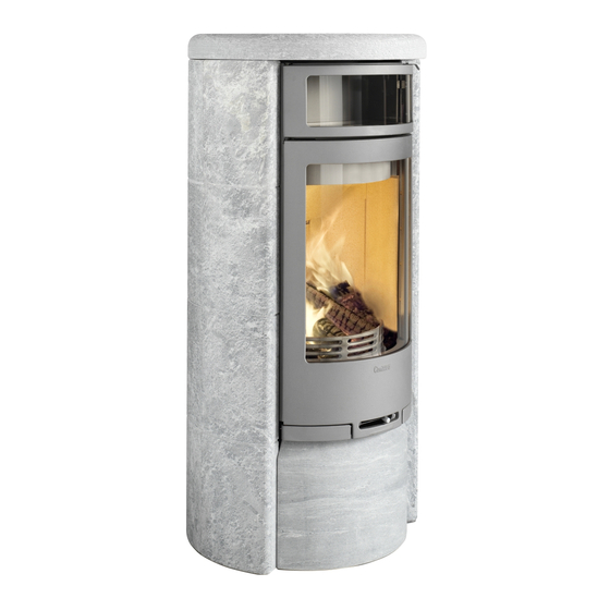
Page 25: Installing The Base Contura 650 (Optional)
Installing the base C 650 (optional) 3-4 mm Screw the 2 screws in each leg at the front edge, Press in the base’s protruding bent edge between leave 3-4 mm between the screw’s head and leg . the side panel and the heads of the screws . -
Page 26: Installing The Drawer (Optional)
Installing the drawer (optional) Important! When installing the drawer, the knockout in the back panel must always be removed for the suppl y of convection air . Slacken off the rear Allen screw three turns . Place the pull-out unit on the base panel . Hook the pull-out unit over the rear Allen screws . - Page 27 NIBE AB/NIBE Brasvärme Box 134 SE-285 23 Markaryd, Sweden • • www .contura .eu...
Need help?
Do you have a question about the 650 and is the answer not in the manual?
Questions and answers